The Flat Dilatometer Test (DMT) in Soil Investigations - Marchetti DMT
The Flat Dilatometer Test (DMT) in Soil Investigations - Marchetti DMT
The Flat Dilatometer Test (DMT) in Soil Investigations - Marchetti DMT

You also want an ePaper? Increase the reach of your titles
YUMPU automatically turns print PDFs into web optimized ePapers that Google loves.
where the gra<strong>in</strong>s are small compared to the<br />
membrane diameter (60 mm). It is not suitable for<br />
gravels, however the blade is robust enough to cross<br />
gravel layers of about 0.5 m thickness.<br />
Due to the balance of zero pressure measurement<br />
method (null method), the <strong>DMT</strong> read<strong>in</strong>gs are highly<br />
accurate even <strong>in</strong> extremely soft - nearly liquid soils.<br />
On the other hand the blade is very robust (can safely<br />
withstand up to 250 kN of push<strong>in</strong>g force) and can<br />
penetrate even soft rocks. Clays can be tested from<br />
c u = 2-4 kPa up to 1000 kPa (marls). <strong>The</strong> range for<br />
moduli M is from 0.4 MPa up to 400 MPa.<br />
2. <strong>DMT</strong> EQUIPMENT COMPONENTS<br />
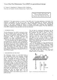
<strong>The</strong> basic equipment for dilatometer test<strong>in</strong>g consists<br />
of the components shown <strong>in</strong> Fig. 2.<br />
Fig. 2. General layout of the dilatometer test<br />
<strong>The</strong> blade is advanced <strong>in</strong>to the ground us<strong>in</strong>g common<br />
field equipment, i.e. push rigs normally used for the<br />
cone penetration test (CPT) or drill rigs. Push rods<br />
are used to transfer the thrust from the <strong>in</strong>sertion rig<br />
to the blade.<br />
<strong>The</strong> general layout of the dilatometer test is shown<br />
<strong>in</strong> Fig. 2. <strong>The</strong> test starts by <strong>in</strong>sert<strong>in</strong>g the dilatometer<br />
<strong>in</strong>to the ground. Soon after penetration, by use of the<br />
control unit, the operator <strong>in</strong>flates the membrane and<br />
takes, <strong>in</strong> about 1 m<strong>in</strong>ute, two read<strong>in</strong>gs:<br />
1) the A-pressure, required to just beg<strong>in</strong> to move the<br />
membrane aga<strong>in</strong>st the soil ("lift-off")<br />
2) the B-pressure, required to move the center of the<br />
membrane 1.1 mm aga<strong>in</strong>st the soil.<br />
A third read<strong>in</strong>g C ("clos<strong>in</strong>g pressure") can also<br />
optionally be taken by slowly deflat<strong>in</strong>g the membrane<br />
soon after B is reached.<br />
<strong>The</strong> blade is then advanced <strong>in</strong>to the ground of one<br />
depth <strong>in</strong>crement (typically 20 cm) and the procedure<br />
for tak<strong>in</strong>g A, B read<strong>in</strong>gs repeated at each depth.<br />
<strong>The</strong> pressure read<strong>in</strong>gs A, B are then corrected by<br />
the values ∆A, ∆B determ<strong>in</strong>ed by calibration to take<br />
<strong>in</strong>to account the membrane stiffness and converted<br />
<strong>in</strong>to p 0 , p 1 .<br />
<strong>The</strong> field of application of the <strong>DMT</strong> is very wide,<br />
rang<strong>in</strong>g from extremely soft soils to hard soils/soft<br />
rocks. <strong>The</strong> <strong>DMT</strong> is suitable for sands, silts and clays,<br />
2.1 DILATOMETER BLADE<br />
2.1.1 Blade and membrane characteristics<br />
<strong>The</strong> nom<strong>in</strong>al dimensions of the blade are 95 mm<br />
width and 15 mm thickness. <strong>The</strong> blade has a cutt<strong>in</strong>g<br />
edge to penetrate the soil. <strong>The</strong> apex angle of the edge<br />
is 24° to 32°. <strong>The</strong> lower tapered section of the tip is<br />
50 mm long. <strong>The</strong> blade can safely withstand up to<br />
250 kN of push<strong>in</strong>g thrust.<br />
<strong>The</strong> circular steel membrane is 60 mm <strong>in</strong> diameter.<br />
Its normal thickness is 0.20 mm (0.25 mm thick<br />
membranes are sometimes used <strong>in</strong> soils which may<br />
cut the membrane). <strong>The</strong> membrane is mounted flush<br />
on the blade and kept <strong>in</strong> place by a reta<strong>in</strong><strong>in</strong>g r<strong>in</strong>g.<br />
2.1.2 Work<strong>in</strong>g pr<strong>in</strong>ciple<br />
<strong>The</strong> work<strong>in</strong>g pr<strong>in</strong>ciple of the <strong>DMT</strong> is illustrated <strong>in</strong><br />
Fig. 3 (see also the photo <strong>in</strong> Fig. 4). <strong>The</strong> blade works<br />
as an electric switch (on/off). <strong>The</strong> <strong>in</strong>sulat<strong>in</strong>g seat<br />
prevents electrical contact of the sens<strong>in</strong>g disc with the<br />
underly<strong>in</strong>g steel body of the dilatometer. <strong>The</strong> sens<strong>in</strong>g<br />
disc is stationary and is kept <strong>in</strong> place press-fitted<br />
<strong>in</strong>side the <strong>in</strong>sulat<strong>in</strong>g seat. <strong>The</strong> contact is signaled by<br />
an audio/visual signal. <strong>The</strong> sens<strong>in</strong>g disc is grounded<br />
(and the control unit emits a sound) under one of the<br />
follow<strong>in</strong>g circumstances:<br />
1) the membrane rests aga<strong>in</strong>st the sens<strong>in</strong>g disc (as<br />
prior to membrane expansion)<br />
2) the center of the membrane has moved 1.1 mm<br />
<strong>in</strong>to the soil (the spr<strong>in</strong>g-loaded steel cyl<strong>in</strong>der<br />
makes contact with the overly<strong>in</strong>g sens<strong>in</strong>g disc).<br />
<strong>The</strong>re is no electrical contact, hence no signal, at<br />
<strong>in</strong>termediate positions of the membrane.<br />
When the operator starts <strong>in</strong>creas<strong>in</strong>g the <strong>in</strong>ternal<br />
pressure (Fig. 3), for some time the membrane does<br />
not move and rema<strong>in</strong>s <strong>in</strong> contact with its metal<br />
support (signal on). When the <strong>in</strong>ternal pressure<br />
3