Data Sheet DB EN EMD-FL-3V-400 - IEC Supply, LLC
Data Sheet DB EN EMD-FL-3V-400 - IEC Supply, LLC
Data Sheet DB EN EMD-FL-3V-400 - IEC Supply, LLC

Create successful ePaper yourself
Turn your PDF publications into a flip-book with our unique Google optimized e-Paper software.
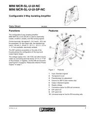
<strong>EMD</strong>-<strong>FL</strong>-<strong>3V</strong>-<strong>400</strong><br />
3-Phase Voltage Monitoring Relay<br />
<strong>Data</strong> <strong>Sheet</strong><br />
08/2004<br />
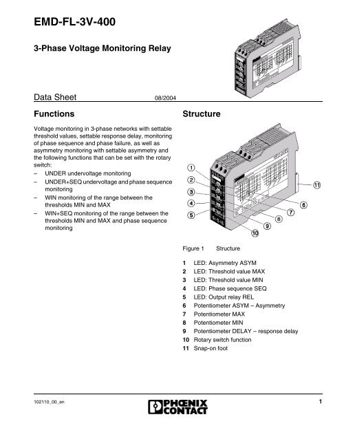
Functions<br />
Structure<br />
Voltage monitoring in 3-phase networks with settable<br />
threshold values, settable response delay, monitoring<br />
of phase sequence and phase failure, as well as<br />
asymmetry monitoring with settable asymmetry and<br />
the following functions that can be set with the rotary<br />
switch:<br />
– UNDER undervoltage monitoring<br />
– UNDER+SEQ undervoltage and phase sequence<br />
monitoring<br />
– WIN monitoring of the range between the<br />
thresholds MIN and MAX<br />
– WIN+SEQ monitoring of the range between the<br />
thresholds MIN and MAX and phase sequence<br />
monitoring<br />
Figure 1<br />
Structure<br />
1 LED: Asymmetry ASYM<br />
2 LED: Threshold value MAX<br />
3 LED: Threshold value MIN<br />
4 LED: Phase sequence SEQ<br />
5 LED: Output relay REL<br />
6 Potentiometer ASYM – Asymmetry<br />
7 Potentiometer MAX<br />
8 Potentiometer MIN<br />
9 Potentiometer DELAY – response delay<br />
10 Rotary switch function<br />
11 Snap-on foot<br />
102110_00_en 1
<strong>EMD</strong>-<strong>FL</strong>-<strong>3V</strong>-<strong>400</strong><br />
Technical <strong>Data</strong><br />
Power <strong>Supply</strong><br />
<strong>Supply</strong> voltage<br />
Connection terminal blocks (electrically isolated)<br />
Tolerance<br />
Nominal frequency<br />
24 V … 240 V AC/DC<br />
A1 - A2<br />
-15% ... +10% AC / -20% ... +25% DC<br />
48 Hz ... <strong>400</strong> Hz<br />
on request<br />
16.6 Hz<br />
Nominal operational power 4.5 VA (1.5 W)<br />
Measuring Input<br />
Time setting range for response delay<br />
Measured value<br />
Measuring input<br />
Connection terminal blocks<br />
Overload capacity<br />
Input resistance<br />
Switching threshold<br />
– max. (relative to U N )<br />
– min. (relative to U N )<br />
Asymmetry<br />
0.1 s … 10 s<br />
AC sinus (48 Hz … 63 Hz)<br />
3(N)~<strong>400</strong> V / 230 V<br />
(N) - L1 - L2 - L3<br />
3(N)~600 V / 346 V<br />
1 MΩ<br />
-20% … +30%<br />
-30% … +20%<br />
5% ... 25% / off<br />
Accuracy<br />
Basic accuracy of scale end value ±5%<br />
Setting accuracy of scale end value ≤ 5%<br />
Repeat accuracy ≤ 2%<br />
Temperature influence<br />
≤ 0.1%/K<br />
2 102110_00_en
<strong>EMD</strong>-<strong>FL</strong>-<strong>3V</strong>-<strong>400</strong><br />
Contact Side (Output)<br />
Contact type<br />
Rated voltage in accordance with <strong>IEC</strong> 60664-1<br />
Switching capacity<br />
– device mounted in row (spacing < 5 mm)<br />
– device not mounted in row (spacing > 5 mm)<br />
Fusing<br />
Mechanical service life<br />
Electrical service life (ohmic load 1000 VA)<br />
Switching rate in accordance with <strong>IEC</strong> 60947-5-1<br />
– max. (with ohmic load 100 VA)<br />
– max. (with ohmic load 1000 VA)<br />
Floating PDT (2x)<br />
250 V AC<br />
750 VA (3 A/250 V AC)<br />
1250 VA (5 A/250 V AC)<br />
5 A fast<br />
20 x 10 6 cycles<br />
2 x 10 5 cycles<br />
60/min.<br />
6/min.<br />
Climatic <strong>Data</strong><br />
Ambient temperature<br />
– operation (<strong>IEC</strong> 60068-1/UL 508)<br />
-25°C … +55°C / -25°C … +40°C<br />
(-13°F ... 131°F / -13°F ... 104°F)<br />
– storage<br />
-25°C … +70°C (-13°F ... 158°F)<br />
Relative humidity 15% … 85%<br />
Climatic class in accordance with <strong>IEC</strong> 60721-3-3 3K3<br />
Contamination class in accordance with <strong>IEC</strong> 60664-1 3<br />
General <strong>Data</strong><br />
Duty cycle 100%<br />
Recovery time<br />
500 ms<br />
Surge voltage category in accordance with<br />
III<br />
<strong>IEC</strong> 60664-1<br />
Rated surge voltage<br />
4 kV<br />
Indicators<br />
Position of output relay: yellow LED<br />
Error in corresponding threshold: red LED<br />
Response delay in corresponding threshold: red LED<br />
ON / OFF<br />
ON / OFF<br />
Flashes<br />
102110_00_en 3
<strong>EMD</strong>-<strong>FL</strong>-<strong>3V</strong>-<strong>400</strong><br />
Housing<br />
Material<br />
Polyamide PA 6.6, self-extinguishing<br />
Degree of protection<br />
IP40<br />
Mounting On 35 mm DIN rails in accordance with <strong>EN</strong> 60715-35<br />
Installation position<br />
As desired<br />
Dimensions (W x H x D)<br />
22.5 mm x 90 mm x 113 mm<br />
(0.886 in. x 3.543 in. x 4.449 in.)<br />
Weight<br />
approx. 160 g<br />
Connection Terminal Blocks<br />
Touch-proof<br />
Degree of protection<br />
Torque, max.<br />
Conductor cross section<br />
– with/without ferrule<br />
– without ferrule<br />
– with/without ferrule<br />
– flexible without ferrule<br />
Yes<br />
IP20<br />
1 Nm<br />
1 x 0.5 … 2.5 mm 2 (AWG 20 ... 14)<br />
1 x 4 mm 2 (AWG 12)<br />
2 x 0.5 mm … 1.5 mm 2 (AWG 20 ... 16)<br />
2 x 2.5 mm 2 (AWG 14)<br />
Ordering <strong>Data</strong><br />
Description Order Designation Order No.<br />
3-phase voltage monitoring relay <strong>EMD</strong>-<strong>FL</strong>-<strong>3V</strong>-<strong>400</strong> 28 66 06 4<br />
4 102110_00_en
<strong>EMD</strong>-<strong>FL</strong>-<strong>3V</strong>-<strong>400</strong><br />
Installation<br />
Connection Examples<br />
Danger of fatal injury!<br />
Never carry out work on live parts!<br />
The monitoring module can be snapped onto all<br />
35 mm DIN rails in accordance with <strong>EN</strong> 60715-35.<br />
An integrated wide range power supply unit allows<br />
voltage in the range of 24 V AC/DC to 240 V AC/DC<br />
to be connected.<br />
Circuit Diagram<br />
Figure 3<br />
Measuring range 3(N)~<strong>400</strong> V / 230 V<br />
Figure 2<br />
Circuit diagram<br />
Figure 4<br />
Measuring range 3(N)~<strong>400</strong> V / 230 V<br />
102110_00_en 5
<strong>EMD</strong>-<strong>FL</strong>-<strong>3V</strong>-<strong>400</strong><br />
Figure 5<br />
Measuring range 3(N)~<strong>400</strong> V / 230 V<br />
with connected neutral conductor<br />
Functional Description<br />
LEDs MIN and MAX flash alternately for all functions<br />
if the minimum value selected for the measured voltage<br />
is greater than the maximum value.<br />
If there is a mains fault when the monitoring module is<br />
activated, the output relay R remains dropped out and<br />
the LED for the relevant threshold lights up.<br />
The desired function is set with the rotary switch<br />
(Figure 6):<br />
U = Undervoltage monitoring UNDER<br />
US = UNDER + SEQ / undervoltage monitoring with<br />
phase sequence monitoring and phase failure<br />
monitoring<br />
W = Window function WIN / monitoring of the range<br />
between the thresholds MIN and MAX<br />
WS = WIN + SEQ / monitoring of the range between<br />
the thresholds MIN and MAX with phase<br />
sequence monitoring and phase failure<br />
monitoring<br />
Figure 6<br />
Rotary switch<br />
6 102110_00_en
<strong>EMD</strong>-<strong>FL</strong>-<strong>3V</strong>-<strong>400</strong><br />
Undervoltage Monitoring – UNDER,<br />
UNDER + SEQ<br />
Figure 7 Undervoltage monitoring –<br />
UNDER, UNDER + SEQ<br />
When the measured voltage (average of the phaseto-phase<br />
voltages) falls below the value set on the<br />
MIN regulator, the response delay (DELAY) starts to<br />
elapse (red LED MIN flashes). When the response<br />
delay has elapsed (red LED MIN lights up), output<br />
relay R drops out (yellow LED REL does not light up).<br />
If the measured voltage falls below the value set on<br />
the MAX regulator, the output relay R picks up again<br />
(yellow LED REL lights up).<br />
Window Function – WIN, WIN + SEQ<br />
The output relay R picks up again (yellow LED REL<br />
lights up) when the measured voltage drops below the<br />
maximum value again (red LED MAX does not light<br />
up). If the measured voltage falls below the value set<br />
on the MIN regulator, the response delay (DELAY)<br />
starts to elapse (red LED MIN flashes). When the response<br />
delay has elapsed (red LED MIN lights up),<br />
output relay R drops out (yellow LED REL does not<br />
light up).<br />
Monitoring Phase Sequence – SEQ<br />
Phase sequence monitoring can be activated for all<br />
functions. If the phase direction of rotation is altered<br />
(red LED SEQ lights up), output relay R drops out<br />
without delay (yellow LED REL does not light up).<br />
Monitoring Phase Failure – SEQ<br />
If one of the phase voltages fails, the response delay<br />
set (DELAY) begins to elapse (red LED SEQ flashes).<br />
When the time delay has elapsed (red LED SEQ lights<br />
up), output relay R drops out (yellow LED REL does<br />
not light up). Reverse voltages (e.g. motors running<br />
on two phases) are not detected by this function. This<br />
is done by monitoring asymmetry with a suitable<br />
choice of thresholds.<br />
Figure 8<br />
Window function – WIN, WIN + SEQ<br />
The output relay R picks up (yellow LED REL lights<br />
up) if the measured voltage (average of the phase-tophase<br />
voltages) exceeds the value set on the MIN<br />
regulator. When the measured voltage exceeds the<br />
value set on the MAX regulator, the response delay<br />
(DELAY) starts to elapse (red LED MAX flashes).<br />
When the response delay has elapsed (red LED MAX<br />
lights up), output relay R drops out (yellow LED REL<br />
does not light up).<br />
102110_00_en 7
<strong>EMD</strong>-<strong>FL</strong>-<strong>3V</strong>-<strong>400</strong><br />
Monitoring Asymmetry<br />
When the asymmetry of the phase-to-phase voltages<br />
exceeds the value set on the ASYM regulator, the<br />
response delay (DELAY) starts to elapse (red LED<br />
ASYM flashes). When the response delay has<br />
elapsed (red LED ASYM lights up), output relay R<br />
drops out (yellow LED REL does not light up).<br />
If the neutral conductor is connected, the phase voltages<br />
(phase-to-neutral voltage) are also monitored for<br />
asymmetry with the neutral conductor. In this particular<br />
application, both values are taken for evaluation for<br />
asymmetry. As soon as one of the two values exceeds<br />
the value set on the ASYM regulator, the response<br />
delay starts to elapse (red LED ASYM flashes). When<br />
the response delay has elapsed (red LED ASYM<br />
lights up), output relay R drops out (yellow LED REL<br />
does not light up).<br />
Monitoring Neutral Conductor Break via<br />
Asymmetry Evaluation<br />
A break in the neutral conductor between the system<br />
and the supply network is recognized as asymmetry<br />
of the phase voltages with the neutral conductor and<br />
the response delay (DELAY) starts to elapse (red LED<br />
ASYM flashes). When the response delay has<br />
elapsed (red LED ASYM lights up), output relay R<br />
drops out (yellow LED REL does not light up).<br />
A break in the neutral conductor between the monitoring<br />
module and the monitored system cannot be<br />
detected.<br />
Make sure you always use the latest documentation.<br />
It can be downloaded at www.phoenixcon.com .<br />
Phoenix Contact Inc.<br />
P.O. Box 4100<br />
Harrisburg, PA 17111-0100<br />
USA<br />
717-944-1300<br />
717-944-1625<br />
info@phoenixcon.com<br />
www.phoenixcon.com<br />
© Phoenix Contact 08/2004 Technical modifications reserved<br />
8 102110_00_en