Data Sheet DB EN MINI MCR-SL-U-UI(-SP)-NC - IEC Supply, LLC
Data Sheet DB EN MINI MCR-SL-U-UI(-SP)-NC - IEC Supply, LLC
Data Sheet DB EN MINI MCR-SL-U-UI(-SP)-NC - IEC Supply, LLC

Create successful ePaper yourself
Turn your PDF publications into a flip-book with our unique Google optimized e-Paper software.
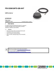
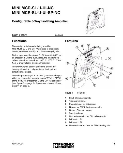
<strong>MINI</strong> <strong>MCR</strong>-<strong>SL</strong>-U-<strong>UI</strong>-<strong>NC</strong><strong>MINI</strong> <strong>MCR</strong>-<strong>SL</strong>-U-<strong>UI</strong>-<strong>SP</strong>-<strong>NC</strong>Configurable 3-Way Isolating Amplifier<strong>Data</strong> <strong>Sheet</strong>04/2005FunctionsFeaturesThe configurable 3-way isolating amplifier<strong>MINI</strong> <strong>MCR</strong>-<strong>SL</strong>-U-<strong>UI</strong>(-<strong>SP</strong>)-<strong>NC</strong> is used to electricallyisolate, condition, amplify, and filter analog signals.On the input side, the signals 0...24 V and 0...30 V canbe processed. On the output side, the standard signals0...20 mA, 4...20 mA, 0...10 V, 2...10 V, 0...5 V or1...5 V are available, electrically isolated.The DIP switches accessible on the side of thehousing allows the configuration of the input andoutput signal ranges.The voltage supply (19.2...30 V DC) can either be providedvia connecting terminal blocks "3"/"4" or "7"/"8"of the modules, or together, via the DIN rail connector(see Figure 5 on page 6). Please also observe "Power<strong>Supply</strong>" on page 7.Figure 1Features1 Input: Standard signals2 Transparent cover3 Potentiometer for adjustment4 Groove for ZBF 6 Zack marker strip5 Output: Standard signals6 <strong>Supply</strong> voltage7 Connection option for DIN rail connector8 DIP switch S19 DIP switch S210 Universal snap-on foot for <strong>EN</strong> mounting rails101744_01_en 1
<strong>MINI</strong> <strong>MCR</strong>-<strong>SL</strong>-U-<strong>UI</strong>(-<strong>SP</strong>)-<strong>NC</strong>Technical <strong>Data</strong>General <strong>Data</strong><strong>Supply</strong> voltageCurrent consumptionPower consumptionTransmission errorwith alignmentwithout alignmentTemperature coefficientmax.typ.Cut-off frequencyStep response (10...90%)Test voltage (input / output / supply)Ambient temperature range19,2...30 V DC< 19 mA, incl. 20 mA load current< 450 mW< 0.1 %< 0.4 %< 0.01 %/K< 0.002 %/K100 Hz3.2 ms1.5 kV, 50 Hz, 1 min.OperationStorageDimensions (W x H x D)-20°C…+65°C-40°C…+85°C6.2 mm x 93.1 mm x 102.5 mmConductor cross section 0.2...2.5 mm 2 (AWG 24...12)Stripping lengthScrew connectionSpring-cage connectionHousing designTests / Approvals12 mm8 mmPolybutylenterephtalate PBT, greenc u FU PROCESS CONTROL EQ<strong>UI</strong>PM<strong>EN</strong>T FORHAZARDOUS LOCATION<strong>SL</strong>ISTED 31Z<strong>NC</strong>lass I Div 2 Groups A, B, C, D T5A) This equipment is suitable for use in Class I,Division 2, Groups A, B, C, D T5 or non-hazardouslocations only.B) Warning - explosion hazard - substitution ofcomponents may impair suitability for Class 1,Division 2.Statement of conformity in acc. with <strong>EN</strong> 60079-15C) Warning - explosion hazard - do not disconnectequipment unless power has been switched off or thearea is known to be non-hazardous.X II 3 G Ex nA II T4 X2 101744_01_en
<strong>MINI</strong> <strong>MCR</strong>-<strong>SL</strong>-U-<strong>UI</strong>(-<strong>SP</strong>)-<strong>NC</strong>Input (see Figure 1, detail 1)Input signal range (configurable)Max. input signalU IN0...24 V0...30 V (standard configuration)50 VInput resistance 125 kΩ, approx. (0...24 V)155 kΩ, approx. (0...30 V)Output (see Figure 1, detail 5) I OUT U OUTOutput signal range (configurable)4...20 mA0...20 mA (standard0...10 V, 2...10 V,0...5 V, 1...5 Vconfiguration)Load ≤ 500 Ω (20 mA) ≥ 10 kΩRipple < 20 mV ss (500 Ω) < 20 mV ssMax. output signal 28 mA / 12,5 V 12,5 V / 22 mAConformance With EMC Guideline 89/336/EEC And Low Voltage Directive 73/23/EECImmunity to Interference According to <strong>EN</strong> 61000-6-2 1Discharge of static electricity (ESD) <strong>EN</strong> 61000-4-2 Criterion B 2Electromagnetic HF field <strong>EN</strong> 61000-4-3 Criterion A 3Fast transients (Burst) <strong>EN</strong> 61000-4-4 Criterion B 4Surge voltage capacities (Surge) <strong>EN</strong> 61000-4-5 Criterion B 4Conducted disturbance <strong>EN</strong> 61000-4-6 Criterion A 3Noise Emission According to <strong>EN</strong> 61000-6-4Noise emission of housing <strong>EN</strong> 55011 5 Class A 61 <strong>EN</strong> 61000 corresponds to <strong>IEC</strong> 610002 Criterion B: Take protective measures against electrostatic discharge.3 Criterion A: Normal operating behavior within the defined limits.4 Criterion B: Temporary impairment to operational behavior that is corrected by the device itself.5 <strong>EN</strong> 55011 corresponds to CI<strong>SP</strong>R116 Class A: Area of application industry.101744_01_en 3
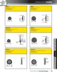
<strong>MINI</strong> <strong>MCR</strong>-<strong>SL</strong>-U-<strong>UI</strong>(-<strong>SP</strong>)-<strong>NC</strong>Ordering <strong>Data</strong>Description Order Designation Order No.Configurable 3-way isolating amplifier<strong>MINI</strong> <strong>MCR</strong>-<strong>SL</strong>-U-<strong>UI</strong>-<strong>NC</strong> 28 65 00 7Screw terminal block, standard configurationConfigurable 3-way isolating amplifierSpring-cage terminal block, standard configuration<strong>MINI</strong> <strong>MCR</strong>-<strong>SL</strong>-U-<strong>UI</strong>-<strong>SP</strong>-<strong>NC</strong> 28 10 07 8AccessoriesDescription Order Designation Order No.DIN rail connector ME 6,2 TBUS-2 1,5/5-ST-3,81 GN 28 69 72 8Power terminal block with screw connection <strong>MINI</strong> <strong>MCR</strong>-<strong>SL</strong>-PTB 28 64 13 4Power terminal block with spring-cage connection <strong>MINI</strong> <strong>MCR</strong>-<strong>SL</strong>-PTB-<strong>SP</strong> 28 64 14 7System power supply (not for Zone 2!) <strong>MINI</strong>-SYS-PS-100-240AC/24DC/1,5 28 66 98 3InstallationScrew ConnectionSpring-Cage ConnectionFigure 2<strong>MINI</strong> <strong>MCR</strong>-<strong>SL</strong>-U-<strong>UI</strong>-<strong>NC</strong>Figure 3<strong>MINI</strong> <strong>MCR</strong>-<strong>SL</strong>-U-<strong>UI</strong>-<strong>SP</strong>-<strong>NC</strong>4 101744_01_en
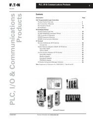
<strong>MINI</strong> <strong>MCR</strong>-<strong>SL</strong>-U-<strong>UI</strong>(-<strong>SP</strong>)-<strong>NC</strong>The device may only be installed and put into operation by qualified personnel. The correspondingnational regulations (e.g. VDE, DIN) must be observed.Notes for Ex:The device is category 3 electrical apparatus. Please observe the instructions given here for installation.The device must be installed in a housing with IP54 protection in acc. with <strong>EN</strong> 60529. Thelimits for mechanical or thermal loads described for the device must not be exceeded. Only devicesdesigned for operation in the hazardous areas of Zone 2 may be connected. Under no circumstancesmay repairs be carried out by the user.Only engage or connect conductors in the hazardous area when the device is deenergized!The assignment of the connecting terminal blocks is shown in Figure 4.Block DiagramFigure 4Block diagramThe <strong>MINI</strong> Analog module can be snapped onto all 35 mm DIN rails corresponding to <strong>EN</strong> 60715.101744_01_en 5
<strong>MINI</strong> <strong>MCR</strong>-<strong>SL</strong>-U-<strong>UI</strong>(-<strong>SP</strong>)-<strong>NC</strong>Using DIN rail connector ME 6,2 TBUS-2 1,5/5-ST-3,81 GN (Order No.: 28 69 72 8)Please also pay particular attention to thedirection of the <strong>MINI</strong> Analog module andDIN rail connector when snapping intoposition:Snap-on foot (Figure 5, detail D 10)below and plug (Figure 5, detail C 11)left!• First position the DIN rail connector in the DIN railto bridge the voltage supply (see Figure 5).Figure 5Mounting/Removing6 101744_01_en
<strong>MINI</strong> <strong>MCR</strong>-<strong>SL</strong>-U-<strong>UI</strong>(-<strong>SP</strong>)-<strong>NC</strong>Power <strong>Supply</strong>Never connect the supply voltage directlyto the DIN rail connector!It is not permitted to draw power from theDIN rail connector or from individual <strong>MINI</strong>Analog modules!Feeding in power via the <strong>MINI</strong> Analog moduleWhere the total current consumption of the aligned<strong>MINI</strong> Analog modules does not exceed 400 mA, thepower can be fed in directly at the connecting terminalblocks of a <strong>MINI</strong> Analog module. We recommendconnecting a 400 mA fuse upstream.Feeding in power with a power terminal blockPower terminal block <strong>MINI</strong> <strong>MCR</strong>-<strong>SL</strong>-PTB(Order No.: 28 64 13 4) or <strong>MINI</strong> <strong>MCR</strong>-<strong>SL</strong>-PTB-<strong>SP</strong>(Order No.: 28 64 14 7), of the same shape, is used tofeed in the supply voltage to the DIN rail connector.We recommend connecting a 2 A fuse upstream.Feeding in the power with a system power supplyunitSystem power supply unit <strong>MINI</strong>-SYS-PS-...(Order No.: 28 66 98 3) with 1.5 A output currentcontacts the DIN rail connector with the supplyvoltage, allowing several <strong>MINI</strong> Analog modules to besupplied from the network.ConfigurationElectrostatic Discharge!The module contains components thatcan be damaged or destroyed by electrostaticdischarge. When handling the module,observe the necessary safetyprecautions against electrostatic discharge(ESD), in accordance with<strong>EN</strong> 61340-5-1 and <strong>EN</strong> 61340-5-2, as wellas <strong>IEC</strong> 61340-5-1 and <strong>IEC</strong> 61340-5-2.The device has the following standard configuration:– Input 0...24 V– Output 4...20 mA(All DIP switches in the "off" position, transmissionerror < 0.1%).DIP SwitchesDIP switches S1and S2 (see Figure 1, details 8 and 9)are used to define the combination of input and outputstandard signal ranges (see "Configuration Table" onpage 8).101744_01_en 7
<strong>MINI</strong> <strong>MCR</strong>-<strong>SL</strong>-U-<strong>UI</strong>(-<strong>SP</strong>)-<strong>NC</strong>Configuration TableDIP S2DIP S1IN OUT 1 2 3 4 5 6 1 20...30 V 0...20 mA off off off off off off off off4...20 mA off off off off off ON off off0...10 V ON off ON off off off off off2...10 V ON off ON off off ON off off0...5 V ON ON off off off off off off1...5 V ON ON off off off ON off off0...24 V 0...20 mA off off off off off off ON off4...20 mA off off off off off ON ON off0...10 V ON off ON off off off ON off2...10 V ON off ON off off ON ON off0...5 V ON ON off off off off ON off1...5 V ON ON off off off ON ON offAlignmentBelow the transparent cover is a potentiometer (see Figure 1, detail 3), with which a fine adjustment of theanalog signals can be carried out after the configuration of the DIP switches has been altered.The transmission error without adjustment is < 0.4%. Using the potentiometer, the error can beadjusted to < 0.1%.Make sure you always use the latest documentation.It can be downloaded at www.download.phoenixcontact.com.A conversion table is available on the Internet atwww.download.phoenixcontact.com/general/7000_en_00.pdf.PHO<strong>EN</strong>IX CONTACT GmbH & Co. KGFlachsmarktstr. 832825 BlombergGermany+ 49 - (0) 52 35 - 3-00+ 49 - (0) 52 35 - 3-4 12 00www.phoenixcontact.comWorldwide Locations:www.phoenixcontact.com/salesnetwork© PHO<strong>EN</strong>X CONTACT 04/2005 Technical modifications reserved8 101744_01_en