RAD-ISM-900 Data Radio Series User Manual - IEC Supply, LLC
RAD-ISM-900 Data Radio Series User Manual - IEC Supply, LLC
RAD-ISM-900 Data Radio Series User Manual - IEC Supply, LLC

You also want an ePaper? Increase the reach of your titles
YUMPU automatically turns print PDFs into web optimized ePapers that Google loves.
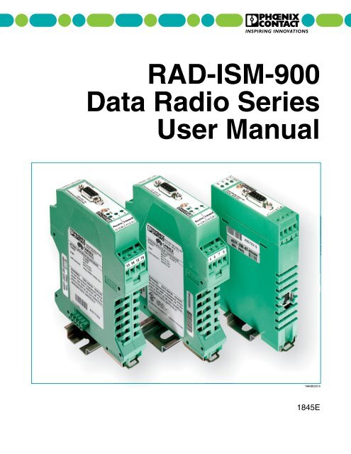
<strong>RAD</strong>-<strong>ISM</strong>-<strong>900</strong><strong>Data</strong> <strong>Radio</strong> <strong>Series</strong><strong>User</strong> <strong>Manual</strong>1845E
<strong>RAD</strong>-<strong>ISM</strong>-<strong>900</strong><strong>Data</strong> <strong>Radio</strong> <strong>Series</strong><strong>User</strong> <strong>Manual</strong><strong>RAD</strong>-<strong>ISM</strong>-<strong>900</strong>-RS232-BD<strong>RAD</strong>-<strong>ISM</strong>-<strong>900</strong>-DATA-BD<strong>RAD</strong>-<strong>ISM</strong>-<strong>900</strong>-DATA-BD-BUSRev E • Issued: August 20071845E
<strong>RAD</strong>-<strong>ISM</strong>-<strong>900</strong> <strong>Radio</strong> <strong>Series</strong><strong>User</strong> <strong>Manual</strong>—Table of ContentsTable of ContentsPrefaceDATA <strong>Series</strong> <strong>User</strong> <strong>Manual</strong>I. Warranty........................................................................................................................ viiII.III.SECTION 1<strong>Data</strong> <strong>Series</strong> OverviewSECTION 2Quick StartA. Important Notice (RF Exposure)..................................................................... viiiB. FCC Part 15 Compliance................................................................................ viiiC. FHSS (Frequency Hopping Spread Spectrum)............................................... viiiAbout this <strong>Manual</strong>....................................................................................................... viiiA. Requirements of the <strong>User</strong> Group ................................................................... viiiB. Purpose of this <strong>Manual</strong>................................................................................... viiiUsing This <strong>Manual</strong>........................................................................................................ viiiA. Finding Information ..........................................................................................ixB. Additional or Related Documentation................................................................ixC. Current Documentation on the Internet.............................................................ixD. Statement of Legal Authority.............................................................................ixE. Validity of Documentation...................................................................................x1.1 General....................................................................................................................... 1-11.2 <strong>Data</strong> <strong>Radio</strong> <strong>Series</strong> Descriptions.................................................................................. 1-11.2.1 <strong>RAD</strong>-<strong>ISM</strong>-<strong>900</strong>-RS232-BD (See Figure 1-1)................................................... 1-11.2.2 <strong>RAD</strong>-<strong>ISM</strong>-<strong>900</strong>-DATA-BD (See Figure 1-2)...................................................... 1-21.2.3 <strong>RAD</strong>-<strong>ISM</strong>-<strong>900</strong>-DATA-BD-BUS (See Figure 1-3)............................................. 1-21.3 Interoperability............................................................................................................. 1-31.4 Remote Diagnostics.................................................................................................... 1-31.5 Features and Benefits of the DATA <strong>Series</strong>.................................................................. 1-31.5.1 Spread Spectrum Systems............................................................................ 1-31.5.2 License-free advantage ................................................................................. 1-42.1 Programming the <strong>Radio</strong>.............................................................................................. 2-12.1.1 Additional Parameters for the <strong>RAD</strong>-<strong>ISM</strong>-<strong>900</strong>-DATA-BD.................................. 2-12.1.2 Additional Parameters for the <strong>RAD</strong>-<strong>ISM</strong>-<strong>900</strong>-DATA-BD-BUS......................... 2-22.2 Installing and Commissioning the <strong>Radio</strong>s................................................................... 2-22.2.1 Common Parameters to all <strong>Radio</strong>s:................................................................ 2-22.2.2 Unique Parameters to the <strong>RAD</strong>-<strong>ISM</strong>-<strong>900</strong>-DATA-BD-BUS............................... 2-21845E Phoenix Contact
<strong>RAD</strong>-<strong>ISM</strong>-<strong>900</strong> <strong>Radio</strong> <strong>Series</strong><strong>User</strong> <strong>Manual</strong>—Table of ContentsTable of ContentsSECTION 3Making Connections and Powering Up3.1 Power Connections..................................................................................................... 3-13.2 RS-232, RS-485 and RS-422 Serial Port Connections............................................... 3-23.2.1 RS-232........................................................................................................... 3-23.2.2 RS-485 and RS-422 – Unique to the <strong>RAD</strong>-<strong>ISM</strong>-<strong>900</strong>-DATA-BD and the<strong>RAD</strong>-<strong>ISM</strong>-<strong>900</strong>-DATA-BD-BUS........................................................................ 3-33.2.3 Serial Port Selection DIP switches – Unique to the <strong>RAD</strong>-<strong>ISM</strong>-<strong>900</strong>-DATA-BD 3-33.3 Antenna Connections.................................................................................................. 3-53.4 Power and Communications Bus Connections on the <strong>RAD</strong>-<strong>ISM</strong>-<strong>900</strong>-DATA-BD-BUS 3-6SECTION 4Programming the <strong>Radio</strong>4.1 Software Installation and Registration......................................................................... 4-24.1.1 Installing the Software (Autorun).................................................................... 4-24.1.2 <strong>Manual</strong>ly Installing the Software..................................................................... 4-24.1.3 Registering the Software................................................................................ 4-34.2 Connecting a <strong>Radio</strong>..................................................................................................... 4-44.3 Using the Project Startup Wizard................................................................................ 4-44.3.1 Creating New Network................................................................................... 4-54.3.2 Monitoring or Modifying an Existing Network................................................. 4-54.4 Creating a New Network (Installation)......................................................................... 4-54.4.1 Creating a New Installation ........................................................................... 4-54.4.2 Creating a New Project.................................................................................. 4-64.4.3 Designating <strong>Radio</strong>s as Slaves or Repeaters.................................................. 4-64.4.4 Selecting a Network ID................................................................................... 4-74.4.5 Selecting a Security ID................................................................................... 4-84.4.6 Selecting an RF Band.................................................................................... 4-94.4.7 Selecting a Retransmit Option...................................................................... 4-104.4.8 Selecting a Default Serial Port Configuration............................................... 4-114.4.9 Final Project Creation................................................................................... 4-134.5 Setting up a Network Using the Project Wizard........................................................ 4-144.5.1 Selecting a <strong>Radio</strong> Name.............................................................................. 4-144.5.2 Filling in the Location Field........................................................................... 4-144.5.3 Selecting a <strong>Radio</strong> (Detection) Type.............................................................. 4-154.5.4 Configuring the Master <strong>Radio</strong>...................................................................... 4-154.5.5 Configuring the Slave and Repeater <strong>Radio</strong>s................................................ 4-164.5.6 Troubleshooting a Failed Connection with a <strong>Radio</strong>...................................... 4-164.6 <strong>Manual</strong>ly Configuring a Network from the <strong>Radio</strong> Profiles List................................... 4-174.6.1 “General” Settings........................................................................................ 4-184.6.2 “Other” Settings............................................................................................ 4-19ii Phoenix Contact 1845E
<strong>RAD</strong>-<strong>ISM</strong>-<strong>900</strong> <strong>Radio</strong> <strong>Series</strong><strong>User</strong> <strong>Manual</strong>—Table of ContentsTable of ContentsSECTION 4 (continued)Programming the <strong>Radio</strong>4.6.3 “Notes” Setting ............................................................................................ 4-204.6.4 “Serial” Settings............................................................................................ 4-214.6.5 Configuring <strong>RAD</strong>-<strong>ISM</strong>-<strong>900</strong>-DATA-BD-BUS Settings..................................... 4-224.6.6 Setting Up Sleep Mode................................................................................ 4-234.6.7 Storing the Project to the <strong>Data</strong>base............................................................. 4-254.6.8 Saving Settings to a <strong>Radio</strong>........................................................................... 4-254.6.9 Configuring other <strong>Radio</strong>s............................................................................. 4-264.7 Modify Existing Network............................................................................................ 4-264.7.1 Modifying an Existing Project on File........................................................... 4-264.7.2 Project File Does Not Exist.......................................................................... 4-274.8 Additional Software Functions................................................................................... 4-274.8.1 <strong>Radio</strong> Profiles List........................................................................................ 4-274.9 Configuring System Options..................................................................................... 4-294.9.1 General Tab.................................................................................................. 4-294.9.2 Password Tab............................................................................................... 4-304.9.3 Serial Port Tab.............................................................................................. 4-304.10 Using the Shortcut Menu Bar.................................................................................... 4-304.10.1 Project Tasks................................................................................................ 4-304.10.2 Bulk Network Tasks...................................................................................... 4-314.10.3 Single <strong>Radio</strong> Tasks....................................................................................... 4-314.10.4 <strong>Radio</strong> Information......................................................................................... 4-314.11 <strong>RAD</strong>-<strong>ISM</strong>-<strong>900</strong>-DATA-BD Primary Port Settings......................................................... 4-334.12 <strong>RAD</strong>-<strong>ISM</strong>-<strong>900</strong>-DATA-BD-BUS DIP-Switch Configuration ......................................... 4-334.13 <strong>RAD</strong>-<strong>ISM</strong>-<strong>900</strong>-RS232-BD Diagnostic Port ............................................................... 4-35SECTION 5DATA-BUS Configuration for I/O Modules (<strong>RAD</strong>-<strong>ISM</strong>-<strong>900</strong>-DATA-BD-BUS Only)5.1 I/O Module Descriptions.............................................................................................. 5-15.2 Point-to-Point Emulation Mode.................................................................................... 5-35.2.1 Connecting and Configuring the I/O modules................................................ 5-35.3 No Emulation Mode of Operation................................................................................ 5-45.4 PLC Emulation Mode of Operation............................................................................. 5-45.5 Addressing the Remote I/O......................................................................................... 5-55.5.1 Address Maps................................................................................................ 5-55.5.2 Rotary Switches........................................................................................... 5-145.5.3 Register Scaling........................................................................................... 5-145.6 Wiring and Fail Condition DIP Switches for the I/O Modules.................................... 5-165.6.1 Analog Input Module.................................................................................... 5-165.6.2 Digital Input Module..................................................................................... 5-171845E Phoenix Contact iii
<strong>RAD</strong>-<strong>ISM</strong>-<strong>900</strong> <strong>Radio</strong> <strong>Series</strong><strong>User</strong> <strong>Manual</strong>—Table of ContentsTable of ContentsSECTION 9System Planning9.1 Accessing the Site....................................................................................................... 9-19.2 Path Quality Analysis.................................................................................................. 9-19.3 Signal Strength............................................................................................................ 9-29.4 Antennas and Cabling................................................................................................. 9-29.4.1 Coaxial Cable Considerations........................................................................ 9-39.5 Antenna Mounting Considerations.............................................................................. 9-49.6 Maintaining System Performance............................................................................... 9-49.6.1 Antennas and Coaxial cable........................................................................... 9-49.6.2 Cable Connections......................................................................................... 9-49.6.3 Power <strong>Supply</strong>................................................................................................. 9-4SECTION 10Using AT Commands and Remote Diagnostics10.1 General..................................................................................................................... 10-110.2 Terminal Programs and Getting Connected.............................................................. 10-110.2.1 Using <strong>RAD</strong>-Link Terminal Program.............................................................. 10-210.2.2 Using Windows HyperTerminal ................................................................... 10-210.3 Programming a Local <strong>Radio</strong>...................................................................................... 10-310.3.1 <strong>Data</strong> Transfer and Configuration Modes....................................................... 10-310.3.2 S-Register Description................................................................................. 10-510.4 Remote <strong>Radio</strong> Programming..................................................................................... 10-610.5 Remote Diagnostics.................................................................................................. 10-710.5.1 Remote Diagnostics using AT Commands................................................... 10-710.5.2 The Remote Diagnostics Port ..................................................................... 10-710.5.3 Remote Diagnostics using <strong>RAD</strong>-Link Software............................................ 10-910.5.4 The Remote Diagnostics Port ..................................................................... 10-910.6 Monitoring and Remote Diagnostics using <strong>RAD</strong>-Link software............................... 10-1010.6.1 Monitor History Tab.................................................................................... 10-1010.6.2 Monitor Alarms Tab.................................................................................... 10-1010.6.3 Network Connection Map........................................................................... 10-1110.6.4 Viewing the Diagnostic Information............................................................ 10-1110.6.5 Using the <strong>Radio</strong> Monitoring Visualization................................................... 10-121845E Phoenix Contact
<strong>RAD</strong>-<strong>ISM</strong>-<strong>900</strong> <strong>Radio</strong> <strong>Series</strong><strong>User</strong> <strong>Manual</strong>—Table of Contentsvi Phoenix Contact 1845E
<strong>RAD</strong>-<strong>ISM</strong>-<strong>900</strong> <strong>Data</strong> <strong>Radio</strong> <strong>Series</strong><strong>User</strong> <strong>Manual</strong>—PrefacePrefaceDATA <strong>Series</strong> <strong>User</strong> <strong>Manual</strong>Preface ContentsI. Warranty............................................................................................................................. xiA. Important Notice (RF Exposure).......................................................................... xiiB. FCC Part 15 Compliance..................................................................................... xiiC. FHSS (Frequency Hopping Spread Spectrum).................................................... xiiII. About this <strong>Manual</strong>............................................................................................................ xiiA. Requirements of the <strong>User</strong> Group ........................................................................ xiiB. Purpose of this <strong>Manual</strong>........................................................................................ xiiIII. Using This <strong>Manual</strong>............................................................................................................. xiiA. Finding Information ..............................................................................................xiiiB. Additional or Related Documentation...................................................................xiiiC. Current Documentation on the Internet................................................................xiiiD. Statement of Legal Authority................................................................................xiiiE. Validity of Documentation.................................................................................... xivI. WarrantyPhoenix Contact warrants its wireless products against defects in materials and workmanshipunder normal use and service for a period of 12 months from the date of purchase.During the warranty period, products determined by Phoenix Contact to be defective, shallat the option of Phoenix Contact, either be repaired at a location authorized by PhoenixContact (and returned free of charges for parts, labor, or shipping), or replaced with anequivalent product. Defective parts replaced by Phoenix Contact shall become the propertyof Phoenix Contact. This Limited Warranty does not cover on-site repair of products. Defectiveproducts must be returned to Phoenix Contact to be repaired or replaced. Phoenix Contactis not responsible for the operation, damage, availability, or loss of use, of the customersupplied equipment being used with a wireless product.This warranty is void under the following circumstances:1. Abnormal use of the product or use in violation of the instructions provide in thismanual2. Improper and/or unauthorized installation or repair of system components1845E Phoenix Contact vii
<strong>RAD</strong>-<strong>ISM</strong>-<strong>900</strong> <strong>Data</strong> <strong>Radio</strong> <strong>Series</strong><strong>User</strong> <strong>Manual</strong>—PrefaceA. Important Notice (RF Exposure)This product is intended for fixed installation applications. In order to comply with FCC/ISCadopted RF exposure requirements, installation of this transmitter system’s antennas mustbe performed in a manner that will provide at least a 6 foot (2 m) clearance from the frontradiating aperture to any user or member of the public.B. FCC Part 15 ComplianceThis device complies with Part 15 of the FCC Rules. Operation is subject to the followingtwo conditions: (1) This device may not cause harmful interference, and (2) this device mustaccept any interference received, including interference that may cause undesired operation.Changes or modifications not expressly approved by Phoenix Contact will void the user’sauthority to operate the equipment.FCC Part 15.247ISC RSS 2101C. FHSS (Frequency Hopping Spread Spectrum)II. About this <strong>Manual</strong>The DATA series of radios utilize a frequency hopping spread spectrum (FHSS) method oftransmitting data. A FHSS radio changes frequencies in a pseudo random fashion therebyavoiding interference and increasing the reliability. Originally designed for battlefield communications,FHSS provides secure, reliable communications in industrial environments.In order to guarantee the safe use of your device, we recommend that you read this manualcarefully. The following notes give you information on how to use this manual.A. Requirements of the <strong>User</strong> GroupThe products described in this manual should be installed/operated/maintained only byqualified application programmers and software engineers, electricians or persons instructedby them. Phoenix Contact assumes no liability for damage to any products resulting fromdisregard of information contained in this manual.B. Purpose of this <strong>Manual</strong>This manual contains the information necessary to understand and to configure a PhoenixContact wireless serial data modem.III. Using This <strong>Manual</strong>This manual contains the information necessary to understand, install, operate, and orderparts for Phoenix Contact wireless serial data modem and associated components. Thetable of contents at the front of this manual provides a paragraph-by-paragraph breakdownof the subject matter covered in each section.viii Phoenix Contact 1845E
<strong>RAD</strong>-<strong>ISM</strong>-<strong>900</strong> <strong>Data</strong> <strong>Radio</strong> <strong>Series</strong><strong>User</strong> <strong>Manual</strong>—PrefaceSpecifications within the text of this manual are given in the International System of Units(SI), with English equivalents in parentheses. Fully capitalized words within the text indicatemarkings found on the equipment. Warnings, Cautions and Notes are used to emphasizecritical instructions:WARNINGAn operating procedure, practice, etc., which, if not carefullyfollowed, could result in personal injury.CAUTIONAn operating procedure, practice, etc., which, if not strictlyobserved, could result in damage to the equipment.NOTEHighlights important information about an operating procedureor the equipment.A. Finding InformationFor ease of finding specific information in this manual, we have provide the following help:• A main table of contents covering all subject matter is provided at the front of thismanual.• A table of contents covering information within a section or an appendix is provided atthe front of each individual section or appendix.B. Additional or Related DocumentationFor specific information on the individual expansion I/O modules, see the correspondingmodule-specific data sheets.C. Current Documentation on the InternetMake sure you are always working with the latest documentation published. The latestchanges or additional information can be found on the Internet at:http://www.phoenixcon.com (Info Service)D. Statement of Legal AuthorityThis manual, including all illustrations contained herein, is copyright protected. Use of thismanual by any third party in departure from the copyright provision is forbidden. Reproduction,translation, and electronic or photographic archiving or alteration requires the expresswritten consent of Phoenix Contact. Violators are liable for damages.Phoenix Contact reserves the right to make any technical changes that serve the purpose oftechnical progress.Phoenix Contact reserves all rights in the case of patent award or listing of a registered design.External products are always named without reference to patent rights. The existenceof such rights shall not be excluded.1845E Phoenix Contact ix
<strong>RAD</strong>-<strong>ISM</strong>-<strong>900</strong> <strong>Data</strong> <strong>Radio</strong> <strong>Series</strong><strong>User</strong> <strong>Manual</strong>—PrefaceE. Validity of DocumentationThis manual mainly contains a description of <strong>RAD</strong>-<strong>ISM</strong>-<strong>900</strong> Serial <strong>Data</strong> Modems that wereavailable when this manual was published.Phoenix Contact reserves the right to make any technical extensions and changes tothe system that would serve the purpose of technical progress. Up to the time that a newmanual revision is published, any updates or changes will be documented on the Internet at:http://www.phoenixcon.com (Info Service) Phoenix Contact 1845E
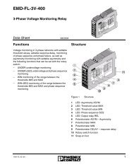
RXTXRFRSSITemp:9 - 30 VDC320 mARC US1845A002LISTED1 Power+<strong>RAD</strong>-<strong>ISM</strong>-<strong>900</strong> <strong>Data</strong> <strong>Radio</strong> <strong>Series</strong>Section 1 - OverviewSECTION 1<strong>Data</strong> <strong>Series</strong> Overview1.1 GeneralSection 1 Contents1.1 General......................................................................................................................1-11.2 <strong>Data</strong> <strong>Radio</strong> <strong>Series</strong> Descriptions.................................................................................1-11.2.1 <strong>RAD</strong>-<strong>ISM</strong>-<strong>900</strong>-RS232-BD (See Figure 1-1)..................................................1-11.2.2 <strong>RAD</strong>-<strong>ISM</strong>-<strong>900</strong>-DATA-BD (See Figure 1-2)....................................................1-21.2.3 <strong>RAD</strong>-<strong>ISM</strong>-<strong>900</strong>-DATA-BD-BUS (See Figure 1-3)............................................1-21.3 Interoperability...........................................................................................................1-31.4 Remote Diagnostics...................................................................................................1-31.5 Features and Benefits of the DATA <strong>Series</strong>.................................................................1-31.5.1 Spread Spectrum Systems...........................................................................1-31.5.2 License-free advantage ...............................................................................1-4The <strong>RAD</strong>-<strong>ISM</strong>-<strong>900</strong> <strong>Data</strong> <strong>Series</strong> family consist of three types of data radios. This sectionprovides general information about these radios.• <strong>RAD</strong>-<strong>ISM</strong>-<strong>900</strong>-RS232-BD• <strong>RAD</strong>-<strong>ISM</strong>-<strong>900</strong>-DATA-BD• <strong>RAD</strong>-<strong>ISM</strong>-<strong>900</strong>-DATA-BD-BUS1.2 <strong>Data</strong> <strong>Radio</strong> <strong>Series</strong> Descriptions1.2.1 <strong>RAD</strong>-<strong>ISM</strong>-<strong>900</strong>-RS232-BD (See Figure 1-1)A 1-watt transceiver for RS-232 protocols, this radio features assured modes for ModbusRTU and Allen-Bradley DF1 protocols. It also has a secondary remote diagnostics port.<strong>RAD</strong>-<strong>ISM</strong>-<strong>900</strong>-RS232-BDOrd No.: 28 67 55 523411 2 3 4SPREAD SPECTRUM TRANSCEIVERPower: Terminals:Trusted Wireless-40° to 70°C 2 Power-<strong>RAD</strong>-<strong>ISM</strong>-<strong>900</strong>-RS232-BDPN: 28 67 55 5WARNING: EXPLOSION HAZARDDo not disconnect equipment unlesspower has been switched off or thearea is known to be non-hazardous.3 Link4 StatusTested to ComplyThis device complies with Part 15 of the FCC rules. Operation iswith FCC Standardssubject to the fo lowing two conditions: (1) this device may not causeharmful interference, and (2) this device must accept any interferencereceived, including interference that may cause undesired operation.APPROBATIOEN/APPROVALSContains FCC ID:Contains CAN ID:UL9EX0A9FHOEM00I1338104550A1845A002-7Made in CANADAFigure 1-1. <strong>RAD</strong>-<strong>ISM</strong>-<strong>900</strong>-RS232-BD <strong>Data</strong> <strong>Radio</strong>1845E Phoenix Contact 1-1
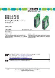
RXTXRSSIANT1845A000RXTXRSSIANT1845A000<strong>RAD</strong>-<strong>ISM</strong>-<strong>900</strong> <strong>Data</strong> <strong>Radio</strong> <strong>Series</strong>Section 1 - Overview1.2.2 <strong>RAD</strong>-<strong>ISM</strong>-<strong>900</strong>-DATA-BD (See Figure 1-2)A 1-watt transceiver for RS-232 and RS-422/485 protocols, this radio features assuredmodes for Modbus RTU and Allen-Bradley DF1 protocols. It also has a secondary remotediagnostics port.+24V GND A BPowerRF LinkFLBL-2357-04R3<strong>RAD</strong>-<strong>ISM</strong>-<strong>900</strong>-DATA-BDPN: 28 67 13 1RF+24V GND A BPower RF Link<strong>RAD</strong>-<strong>ISM</strong>-<strong>900</strong>-DATA-BDPN: 28 67 13 1SPREAD SPECTRUM TRANSCEIVERPOWER ................ 12 - 30 V dc (5 A max)Trusted WirelessTEMP .............. -40 to 70°C (-40 to 158°F)LINK CONTACT ..............2A @ 250 V ac/30 V dc.Res.WARNING: EXPLOSION HAZARDDo not disconnect equipment unlesspower has been switched off or thearea is known to be non-hazardous.APPROVALS1845A011-4Figure 1-2. <strong>RAD</strong>-<strong>ISM</strong>-<strong>900</strong>-DATA-BD <strong>Data</strong> <strong>Radio</strong>1.2.3 <strong>RAD</strong>-<strong>ISM</strong>-<strong>900</strong>-DATA-BD-BUS (See Figure 1-3)A 1-watt transceiver for RS-232 and RS-422/485 protocols, this radio features assuredmodes for Modbus RTU and Allen-Bradley DF1 protocols. It can operate in PLC emulationmode, where expandable I/O modules may be bussed on to the radio and addressed viaModbus RTU or DF1. Remote diagnostics may also be performed using this radio with somerestrictions (see Section 10, Paragraph 10.5.2)V AC+24V GND A BPowerRF LinkFLBL-2457-02R4<strong>RAD</strong>-<strong>ISM</strong>-<strong>900</strong>-DATA-BD-BUSPN: 28 67 29 6RF+24V GND A BPower RF Link<strong>RAD</strong>-<strong>ISM</strong>-<strong>900</strong>-DATA-BD-BUSPN: 28 67 29 6SPREAD SPECTRUM TRANSCEIVERPOWER ................ 12 - 30 V dc (5 A max)Trusted WirelessTEMP .............. -40 to 70°C (-40 to 158°F)LINK CONTACT ..............2A @ 250 V ac/30 V dc.Res.WARNING: EXPLOSION HAZARDDo not disconnect equipment unlesspower has been switched off or thearea is known to be non-hazardous.APPROVALS1845A003-4Figure 1-3. <strong>RAD</strong>-<strong>ISM</strong>-<strong>900</strong>-DATA-BD-BUS <strong>Data</strong> <strong>Radio</strong>1.2.3.1 I/O Expansion Modules and their FunctionsI/O expansion modules may be bussed onto a <strong>RAD</strong>-<strong>ISM</strong>-<strong>900</strong>-DATA-BD-BUS to read or writeanalog (0-22 mA) or digital (on/off) signals from sensors or other process equipment usingModbus RTU or Allen-Bradley DF1.A <strong>RAD</strong>-IN-4A-I module will accept four (4) analog input signals. A <strong>RAD</strong>-OUT-4A-I module will output four (4) analog signals, with available 24 V DC connectionsto power a device. A <strong>RAD</strong>-IN-8D module; accepts eight (8) digital input signals(5-36 V AC/DC), while a <strong>RAD</strong>-OUT-8D-REL will give eight (8) digital relay contacts1-2 Phoenix Contact 1845E
<strong>RAD</strong>-<strong>ISM</strong>-<strong>900</strong> <strong>Data</strong> <strong>Radio</strong> <strong>Series</strong>Section 1 - Overview1.3 Interoperability1.4 Remote Diagnostics(2 A at 250 V AC/30 V DC). The <strong>RAD</strong>-IN+OUT-2D-1A-I module features one (1) eachanalog input, analog output, and two (2) each digital input and digital output. The<strong>RAD</strong>-IN-2D-CNT is a digital input pulse module that accepts two (2) pulse/frequencyinputs, and the <strong>RAD</strong>-OUT-2D-CNT is a digital pulse output module that provides two(2) pulse/frequency outputs.All radios in the data series are interoperable. This means that as long as the protocol isthe same throughout the network, any of the radios may be used. Moreover, RS-232 andRS-422/485 may be used in the same network with no converter necessary. For example, a<strong>RAD</strong>-<strong>ISM</strong>-<strong>900</strong>-RS232-BD may be used as a master to a <strong>RAD</strong>-<strong>ISM</strong>-<strong>900</strong>-DATA-BD operatingin RS-485/422 mode with an RS-485/422 slave device.The remote diagnostics feature allows the user to connect to the master radio using<strong>RAD</strong>-Link software for remote programming and system health information. Each slave radiowill be polled for critical operating information. All radios have the same remote diagnosticscapability with the exception of the DATA-BD-BUS when it is functioning as a master. Due toa lack of a secondary serial port (the secondary port is the 5-pin BUS connector), a DATA-BD-BUS radio when acting as a master and having data passed through its primary port,cannot access remote radios for diagnostics purposes using the <strong>RAD</strong>-Link software or ATcommands. You can access these functions through the primary serial port, but that meansthe host PC/PLC must be disconnected. Therefore if you require this feature, you should useeither the RS232-BD or DATA-BD as the master.1.5 Features and Benefits of the DATA <strong>Series</strong>The <strong>RAD</strong>-<strong>ISM</strong>-<strong>900</strong> <strong>Data</strong> series uses state of the art technology and components to deliverreliable, unsurpassed performance. Some of these features include:• Frequency Hopping Technology – to ensure radio performance in noisy industrialplant environments• High-Quality Filters – on the receivers to prevent unwanted RF noise from interferingwith the desired signal.• Surface Mount Components – to decrease the size of the <strong>RAD</strong>-<strong>ISM</strong>-<strong>900</strong>-RS232-BDto allow mounting in small enclosures.• Iris <strong>Radio</strong> Protocol – a proprietary RF protocol developed to increase data securityand enable features such as auto-routing.• Remote Diagnostics Port – an auxiliary port that can be used to query and programremote <strong>RAD</strong>-<strong>ISM</strong>-<strong>900</strong>-RS232-BD’s.• RF Link Dry Contact – a contact that changes state if the radio link is lost – allowsfor wiring equipment in a fail-safe fashion or simplifying PLC code by monitoring itscondition for communications status.Received Signal Strength Indicator – a voltage test point that indicates how strongthe received signal is – simplifying antenna aiming.1.5.1 Spread Spectrum SystemsSpread Spectrum (SS) this is one of the newest technologies to be applied to radio-basedSCADA systems. Originally developed to provide jam-resistant military communications,Spread Spectrum uses a modulation technique that distributes a transmitter’s signal overa very wide bandwidth, making it virtually undetectable to a conventional radio receiver, orwhat the military calls Low Probability of Intercept (LPI).1845E Phoenix Contact 1-3
<strong>RAD</strong>-<strong>ISM</strong>-<strong>900</strong> <strong>Data</strong> <strong>Radio</strong> <strong>Series</strong>Section 1 - OverviewTwo SS techniques commonly used today are Frequency Hopping and Direct Sequence.Frequency hopping systems employ a narrow band, channel-switching scheme whereby thetransmitter moves rapidly among a predetermined set of frequencies. The time spent on anyone frequency is only a fraction of a second. The receiving station(s) are programmed to“follow” the transmitter in step with the hopping pattern.Direct sequence radios spread their RF energy across a wide “chunk” of spectrum ratherthan hopping among discrete channels. The amount of energy on any frequency is extremelylow, but when the signal is “de-spread” at the receiving end through a compression,a usable signal results. Direct sequence systems are commonly used in short-range LANapplications.1.5.2 License-free advantageA major advantage of Spread Spectrum is that many users can occupy a given band at thesame time without causing serious interference to one another. This offers many countrieslicense-free operation of SS systems with certain restrictions.In the United States, for example, no license is required for 902-928 MHz SS operation witha maximum transmitter power of 1 watt (30 dBm) and an antenna system gain that limits effectiveradiated power (ERP) to 36 dBm or less. This means that for a one 1 watt transmitter,an antenna system with 6 dB of gain may be used. When antenna systems of greater gainare used, transmitter power must be decreased accordingly by cumulative signal losses inconnectors, cables and surge arrestors.SS is an ideal solution in many SCADA applications because it eliminates the time andexpense involved with licensing while providing a level of performance that can approachlicensed systems. However, because of the output power and antenna gain limits imposedon SS systems, station efficiency is even more critical than with licensed networks. Thepath planning, antenna, and coaxial cable issues discussed earlier apply in whole for FHSSsystems.1-4 Phoenix Contact 1845E
<strong>RAD</strong>-<strong>ISM</strong>-<strong>900</strong> <strong>Data</strong> <strong>Radio</strong> <strong>Series</strong>Section 2 - Quick StartSECTION 2Quick StartSection 2 Contents2.1 Programming the <strong>Radio</strong>.............................................................................................2-12.1.1 Additional Parameters for the <strong>RAD</strong>-<strong>ISM</strong>-<strong>900</strong>-DATA-BD................................2-12.1.2 Additional Parameters for the <strong>RAD</strong>-<strong>ISM</strong>-<strong>900</strong>-DATA-BD-BUS........................2-22.2 Installing and Commissioning the <strong>Radio</strong>s..................................................................2-22.2.1 Common Parameters to all <strong>Radio</strong>s:..............................................................2-22.2.2 Unique Parameters to the <strong>RAD</strong>-<strong>ISM</strong>-<strong>900</strong>-DATA-BD-BUS.............................2-22.1 Programming the <strong>Radio</strong>1. Apply 24 V DC power to the radio.2. Connect a straight through cable from the serial port of the PC to the serial port ofthe radio.3. Download and run the <strong>RAD</strong>-Link software. See Section 4 for software installationinstructions.4. Select “Create New Project” from the Project Startup Wizard.5. Select either “New Network with Repeaters” or “New Network Without Repeaters”.6. Fill in the number of Slave radios and Repeater/Slave radios (if applicable) and click“Next”.7. The wizard will prompt you to enter a Network ID, Security ID, RF Band, and RetransmitMode. Click “Next” after each value has been entered to move to the next parameter.8. Fill in fields for Baud Rate, Parity, <strong>Data</strong> Bits, Stop Bits, Handshaking, and Buffer andclick “Next”.9. Click on “Setup Network” to begin programming individual radios.10. Enter name and location information for the radio and click “Configure <strong>Radio</strong>”. Repeatthis step for each radio in the network.2.1.1 Additional Parameters for the <strong>RAD</strong>-<strong>ISM</strong>-<strong>900</strong>-DATA-BD1. Remove power from the radio and press in the release tabs on either side of the radiojust below the terminal blocks. Remove the plastic housing from the circuit boardexposing the DIP switches.2. Set the DIP switches accordingly to configure for use with RS232/485/422.3. Reinstall the housing.1845E Phoenix Contact 2-1
<strong>RAD</strong>-<strong>ISM</strong>-<strong>900</strong> <strong>Data</strong> <strong>Radio</strong> <strong>Series</strong>Section 2 - Quick Start2.1.2 Additional Parameters for the <strong>RAD</strong>-<strong>ISM</strong>-<strong>900</strong>-DATA-BD-BUS1. In the project window, double click on the name of a radio to bring up the <strong>Radio</strong> Configurationwindow.2. Under the General tab, set the <strong>Radio</strong> Type field to DATA-BD-BUS. This will make twoadditional tabs available: DATA-BD-BUS and Sleep Mode.3. Under the DATA-BD-BUS tab, set the Main Serial Port and the Emulation Mode.4. Click “Store to Project” (available at the bottom of every tab) and follow the prompts todownload the configuration to the radio.5. Repeat steps 1 thru 4 for each <strong>RAD</strong>-<strong>ISM</strong>-<strong>900</strong>-DATA-BD-BUS radio in the project window.2.2 Installing and Commissioning the <strong>Radio</strong>s2.2.1 Common Parameters to all <strong>Radio</strong>s:1. Connect each device to the radio’s RS232 port or 485/422 port as selected in thesoftware or DIP switches (if applicable).2. Connect the antenna to the gold antenna connector on the top of the radio and mountthe antenna.3. Apply power to the radio and commence communications.2.2.2 Unique Parameters to the <strong>RAD</strong>-<strong>ISM</strong>-<strong>900</strong>-DATA-BD-BUS1. Plug in Analog/Digital/Input/Output module(s) to each slave radio.2. Wire Analog/Discrete signals to the I/O module(s).3. Refer to the Address Map in Section 5, Paraqgraph 5.5.1 to determine what input/outputchannels are mapped to which registers.2-2 Phoenix Contact 1845E
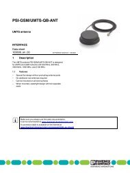
4321<strong>RAD</strong>-<strong>ISM</strong>-<strong>900</strong> <strong>Data</strong> <strong>Radio</strong> <strong>Series</strong>Section 3 - Connections and Power-upSECTION 3Making Connections andPowering UpSection 3 Contents3.1 Power Connections....................................................................................................3-13.2 RS-232, RS-485 and RS-422 Serial Port Connections.............................................3-23.2.1 RS-232..........................................................................................................3-23.2.2 RS-485 and RS-422 – Unique to the <strong>RAD</strong>-<strong>ISM</strong>-<strong>900</strong>-DATA-BD and the<strong>RAD</strong>-<strong>ISM</strong>-<strong>900</strong>-DATA-BD-BUS.......................................................................3-33.2.3 Serial Port Selection DIP switches – Unique to the<strong>RAD</strong>-<strong>ISM</strong>-<strong>900</strong>-DATA-BD...............................................................................3-33.3 Antenna Connections................................................................................................3-53.4 Power and Communications Bus Connections on the<strong>RAD</strong>-<strong>ISM</strong>-<strong>900</strong>-DATA-BD-BUS....................................................................................3-63.1 Power ConnectionsThe radios can be powered from a DC voltage ranging from 9 to 30 V DC. The power supplyshould be regulated and not fluctuate by more than 10% of its rated output. See Figure 3-1.It is recommended that a voltage surge arrestor be installed to prevent power surges fromdamaging the equipment. The wiring between the surge arrestor and the radio should be asshort as possible, following the manufacturer’s guidelines.<strong>RAD</strong>-<strong>ISM</strong>-<strong>900</strong>-RS232-BD<strong>RAD</strong>-<strong>ISM</strong>-<strong>900</strong>-DATA-BD<strong>RAD</strong>-<strong>ISM</strong>-<strong>900</strong>-DATA-BD-BUS13 14 15 161 2 3 413 14 15 161 2 3 413 14 15 161 2 3 49 1 0 1 1 1 29 1 0 1 1 1 2+24V GND A B9 1 0 1 1 1 2+24V GND A BPowerRF LinkPowerRF Link- - + DCOKOUT DC 24V 1A- - + +MINI POWER22.5 –28.5VDCDCOK5 4 3 2 19 8 7 6<strong>RAD</strong>-<strong>ISM</strong>-<strong>900</strong>-RS232-BDOrd No .: 28 67 55 5- - + DCOKOUT DC 24V 1A- - + +MINI POWER22.5 –28.5VDCDCOK<strong>RAD</strong>-<strong>ISM</strong>-<strong>900</strong>- DATA-BDPN: 28 67 13 1FLBL-2457-02R 4- - + DCOKOUT DC 24V 1A- - + +MINI POWER22.5 –28.5VDCDCOK<strong>RAD</strong>-<strong>ISM</strong>-<strong>900</strong>- DATA-BD-B USPN: 28 67 29 6FLBL-2457-02R 4AN TAN TIN 100–240 VA CRSSIRFTXRXIN 100–240 VA CRSSIIN 100–240 VA CRSSIL(+) NC NC L(-)1919A001L(+) NC NC L(-)RFTXRXL(+) NC NC L(-)RFTXRXReceiveTransmitReceiveTransmit1 2 3 41 2 3 4A(+) B(-) A(+) B(-)1 2 3 4A(+) B(-) A(+) B(-)13 14 15 1613 14 15 161919A0021869A002To 120 V acTo 120 V acTo 120 V acFigure 3-1. <strong>Data</strong> <strong>Series</strong> <strong>Radio</strong> to Power <strong>Supply</strong> Connections1845B0241845E Phoenix Contact 3-1
<strong>RAD</strong>-<strong>ISM</strong>-<strong>900</strong> <strong>Data</strong> <strong>Radio</strong> <strong>Series</strong>Section 3 - Connections and Power-up3.2 RS-232, RS-485 and RS-422 Serial Port Connections3.2.1 RS-232In order to program the radio using the <strong>RAD</strong>-Link software, you will need to connect the radioto your computer's serial port. The interconnecting cable needs to have DB9 connectorson each end and wired in a “straight through” fashion.When you have the correct RS-232 cable connecting the radio to the computer or PLC/industrialinstrument, the TX LED on the radio will go solid green when power is applied toboth devices. (This TX LED will also flash when data is passed).Note on Serial Cables: There are 2 types of serial port cables that both have DB9(9- pin sub D) connectors. See Figure 3-2. One is called a straight through 9-pin serialport cable and the other is called a null modem cable. On a straight through cable, itis wired as just that – straight through, in other words, pin 1 is connected to pin 1, pin2 to 2, etc. A null modem cable crosses over pins 2 and 3 (transmit and receive data)and also crosses over pins 7 and 8 (clear-to-send (CTS) and ready-to-send (RTS)).A null modem cable is designed to allow two devices to be connected together whenthey both function as data terminal equipment (DTE) or when they both function asdata communications equipment (DCE). By swapping the pins, it connects inputs tooutputs and vice versa for proper operation.Figure 3-2. Wiring Diagram - RS-232 Port InterfaceEquipment with serial ports can be designed as either DTE or DCE. This determinesthe functions of pins 2 & 3, and 7 & 8. For example, if pin 7 is an output on one end,then it will have to be an input on the other end. Computers are typically designedas DTE whereas modems and radio modems are designed as DCE. Programmable3-2 Phoenix Contact 1845E
<strong>RAD</strong>-<strong>ISM</strong>-<strong>900</strong> <strong>Data</strong> <strong>Radio</strong> <strong>Series</strong>Section 3 - Connections and Power-upLogic Controllers (PLC’s) flow computers and other industrial instruments could beeither DCE or DTE.To connect a DCE device to a DTE device, a straight through cable is used. Toconnect two DCE devices together or to connect two DTE devices together, a nullmodem cable is required.3.2.2 RS-485 and RS-422 – Unique to the <strong>RAD</strong>-<strong>ISM</strong>-<strong>900</strong>-DATA-BDand the <strong>RAD</strong>-<strong>ISM</strong>-<strong>900</strong>-DATA-BD-BUSOne set of terminals (13 – 16) can be used to connect the radio to external devices usingRS-485 or RS-422 – differential standards typically used for the transmission of data overmuch greater distances than is possible with RS-232. Both 2-wire and 4-wire configurationsare supported. See Figure 3-3. Although the 4-wire configuration supports full duplex communications,the radio is only half duplex over the air.RS485 2-Wire ConnectionRS485/RS422 4-Wire Connection1 2 3 41 2 3 4+24V GND A B+24V GND A BPowerRF LinkPowerRF Link<strong>RAD</strong>-<strong>ISM</strong>-<strong>900</strong>- DATA-BDPN: 28 67 13 1FLBL-2457-02R 4<strong>RAD</strong>-<strong>ISM</strong>-<strong>900</strong>- DATA-BDPN: 28 67 13 1FLBL-2457-02R 4AN TAN TRSSIRSSIRFTXRXRFTXRXReceiveTransmitA(+) B(-) A(+) B(-)ReceiveTransmitA(+) B(-) A(+) B(-)13 14 15 1613 14 15 16+ -Exter nal De viceTXD (A+)TXD (B-)RXD (A+)RXD (B-)1845A133Exter nal De viceFigure 3-3. Wiring Diagram – RS-485 and RS-485 /RS-4223.2.3 Serial Port Selection DIP switches – Unique to the<strong>RAD</strong>-<strong>ISM</strong>-<strong>900</strong>-DATA-BDOn the <strong>RAD</strong>-<strong>ISM</strong>-<strong>900</strong>-DATA-BD there are internal DIP switches that determine which serialport is to be used. They allow selection of RS-232 port or the RS-485/422 port, and theyalso determine if the RS-485/422 port is to operate in 2-wire or 4-wire configuration.To adjust the port, do the following:1. Using a small slotted screwdriver, press in on the latch located just below the terminalblocks on either side of the housing. Then while holding the latch depressed, slide the1845E Phoenix Contact 3-3
<strong>RAD</strong>-<strong>ISM</strong>-<strong>900</strong> <strong>Data</strong> <strong>Radio</strong> <strong>Series</strong>Section 3 - Connections and Power-upplastic housing down to expose the DIP switches. See Figure 3-4.Terminal BlockLatch1845A027Figure 3-4. Opening Housing to Access DIP Switches2. Using a slotted screwdriver, adjust the DIP switches according to the labels next tothem. See Figure 3-5.Switch 1 RS232 Port OFFSwitch 1 RS422/RS488 ONSwitch 2 2-wire half duplex OFFSwitch 2 4-wire full duplex ONSwitch 3 Not connectedSwitch 4 Not connectedDIP SwitchesFigure 3-5. DIP Switch Setings1845A0283. Reinstall the plastic housing onto the circuit board.NoteIf you have selected the RS-485/422 port for data communicationswith your PLC’s/industrial instruments, but wish toreprogram the radio using the <strong>RAD</strong>-Link software, you will needto reset the radio for RS-232 communications. Once programmingis complete, you can then set the radio for RS-485/422communications and connect to your end devices.One radio can be connected to end devices using RS-232 andother radios can be connected to end devices using RS-485 or422. All radios in a network do not have to be set the same.3-4 Phoenix Contact 1845E
<strong>RAD</strong>-<strong>ISM</strong>-<strong>900</strong> <strong>Data</strong> <strong>Radio</strong> <strong>Series</strong>Section 3 - Connections and Power-up3.3 Antenna ConnectionsAn antenna should be connected to the gold antenna connector on the top of the radio,labeled “ANT”. See Figure 3-6. The connector on the radio is an MCX female. If the transmissiondistance is less than 50 feet, the radios may link with no antennas connected. Thisis suitable for bench testing, however when the radios are installed in their final location, anantenna should be connected to provide a load for the RF power amplifier.CAUTIONThe antennas of two radios should never touch eachother to prevent overloading the RF power amplifier.Caution should be used to prevent ground loops causedby the antenna ground (through the antenna mountingbracket), power supply ground and possibly theRS-232/485 connection ground. All of these should usea single ground point to prevent ground loops.NotesThe shield of the antenna can be grounded or ungrounded.It does not affect the performance or RF propagation. It doeshave an impact on lightning protection.Refer to Section 9 for more information about antenna systems.MCX FemaleAntenna Connection1845A029Figure 3-6. Antenna Connection (Typical on all radios)1845E Phoenix Contact 3-5
<strong>RAD</strong>-<strong>ISM</strong>-<strong>900</strong> <strong>Data</strong> <strong>Radio</strong> <strong>Series</strong>Section 3 - Connections and Power-up3.4 Power and Communications Bus Connections on the<strong>RAD</strong>-<strong>ISM</strong>-<strong>900</strong>-DATA-BD-BUSUnique to the <strong>RAD</strong>-<strong>ISM</strong>-<strong>900</strong>-DATA-BD-BUS is a 5-pin male and 5-pin female connectoron either side of the radio. See Figure 3-7. This allows I/O modules to be connected to theradio. <strong>Data</strong> communications and power are transmitted through this connector to the I/Omodules. Up to 8 I/O modules can be connected to each transceiver. Any combination of thedifferent types of I/O modules can be connected to each radio.The modules can be connected to either side of the radio. In hot climates, it is recommendedthat all of the I/O modules be connected to only one side of the radio to maximize heatdissipation.See Section 5.0 for more details on the I/O modules.5-pin MaleConnector5-pin FemaleConnector1845A030Figure 3-7. <strong>RAD</strong>-<strong>ISM</strong>-<strong>900</strong>-DATA-BD-BUS Bus Connectors3-6 Phoenix Contact 1845E
<strong>RAD</strong>-<strong>ISM</strong>-<strong>900</strong> <strong>Radio</strong> <strong>Series</strong>Section 4 - Programming the <strong>Radio</strong>SECTION 4Programming the <strong>Radio</strong>Section 4 Contents4.1 Software Installation and Registration.......................................................................4-24.1.1 Installing the Software (Autorun)...................................................................4-24.1.2 <strong>Manual</strong>ly Installing the Software...................................................................4-24.1.3 Registering the Software..............................................................................4-34.2 Connecting a <strong>Radio</strong>...................................................................................................4-44.3 Using the Project Startup Wizard...............................................................................4-44.3.1 Creating New Network..................................................................................4-54.3.2 Monitoring or Modifying an Existing Network................................................4-54.4 Creating a New Network (Installation).......................................................................4-54.4.1 Creating a New Installation ..........................................................................4-54.4.2 Creating a New Project.................................................................................4-64.4.3 Designating <strong>Radio</strong>s as Slaves or Repeaters................................................4-64.4.4 Selecting a Network ID.................................................................................4-74.4.5 Selecting a Security ID.................................................................................4-84.4.6 Selecting an RF Band...................................................................................4-94.4.7 Selecting a Retransmit Option....................................................................4-104.4.8 Selecting a Default Serial Port Configuration..............................................4-114.4.9 Final Project Creation.................................................................................4-134.5 Setting up a Network Using the Project Wizard.......................................................4-144.5.1 Selecting a <strong>Radio</strong> Name.............................................................................4-144.5.2 Filling in the Location Field.........................................................................4-144.5.3 Selecting a <strong>Radio</strong> (Detection) Type.............................................................4-154.5.4 Configuring the Master <strong>Radio</strong>.....................................................................4-154.5.5 Configuring the Slave and Repeater <strong>Radio</strong>s...............................................4-164.5.6 Troubleshooting a Failed Connection with a <strong>Radio</strong>.....................................4-164.6 <strong>Manual</strong>ly Configuring a Network from the <strong>Radio</strong> Profiles List..................................4-174.6.1 “General” Settings.......................................................................................4-184.6.2 “Other” Settings...........................................................................................4-194.6.3 “Notes” Setting ...........................................................................................4-204.6.4 “Serial” Settings..........................................................................................4-214.6.5 Configuring <strong>RAD</strong>-<strong>ISM</strong>-<strong>900</strong>-DATA-BD-BUS Settings...................................4-224.6.6 Setting Up Sleep Mode...............................................................................4-234.6.7 Storing the Project to the <strong>Data</strong>base............................................................4-254.6.8 Saving Settings to a <strong>Radio</strong>..........................................................................4-254.6.9 Configuring other <strong>Radio</strong>s............................................................................4-261845E Phoenix Contact 4-1
<strong>RAD</strong>-<strong>ISM</strong>-<strong>900</strong> <strong>Radio</strong> <strong>Series</strong>Section 4 - Programming the <strong>Radio</strong>Section 4 Contents (Continued)4.7 Modify Existing Network..........................................................................................4-264.7.1 Modifying an Existing Project on File..........................................................4-264.7.2 Project File Does Not Exist.........................................................................4-274.8 Additional Software Functions.................................................................................4-274.8.1 <strong>Radio</strong> Profiles List.......................................................................................4-274.9 Configuring System Options....................................................................................4-294.9.1 General Tab................................................................................................4-294.9.2 Password Tab..............................................................................................4-304.9.3 Serial Port Tab............................................................................................4-304.10 Using the Shortcut Menu Bar..................................................................................4-304.10.1 Project Tasks...............................................................................................4-304.10.2 Bulk Network Tasks.....................................................................................4-314.10.3 Single <strong>Radio</strong> Tasks.....................................................................................4-314.10.4 <strong>Radio</strong> Information.......................................................................................4-314.11 <strong>RAD</strong>-<strong>ISM</strong>-<strong>900</strong>-DATA-BD Primary Port Settings.......................................................4-334.12 <strong>RAD</strong>-<strong>ISM</strong>-<strong>900</strong>-DATA-BD-BUS DIP-Switch Configuration ........................................4-334.13 <strong>RAD</strong>-<strong>ISM</strong>-<strong>900</strong>-RS232-BD Diagnostic Port ..............................................................4-354.1 Software Installation and RegistrationThe software is available on CD ROM or may be downloaded from our website at:http://www.phoenixcon.com/wireless.4.1.1 Installing the Software (Autorun)1. Insert it into the computer’s CD ROM drive.2. The Auto run feature should automatically start the installation process.3. Click “Install” and follow the prompts until the installation process has been completed.NoteIf the Autorun feature does not recognize that new softwarehas been placed in the drive, the user will need to manuallyinstall the software as outlined below.4.1.2 <strong>Manual</strong>ly Installing the Software1. From Windows START menu, select Run.2. Click “Browse” and find the drive letter corresponding to your system’s CD-ROM drive.3. Open the appropriate drive and find the setup file.4. Double click the setup file to launch the Installation Wizard.5. Follow the prompts until the installation process has been completed.4-2 Phoenix Contact 1845E
<strong>RAD</strong>-<strong>ISM</strong>-<strong>900</strong> <strong>Radio</strong> <strong>Series</strong>Section 4 - Programming the <strong>Radio</strong>4.1.3 Registering the SoftwareThe basic version of the software will allow you to set up, configure and modify a network. Inorder to activate monitoring and diagnostics features, a diagnostic software license must bepurchased.To enter the registration information, click “Help” from the Menu Bar and select “Registration”.The registration window will open as shown in Figure 4-1. Enter the Installation Codefrom the back of the CD jewel case. Contact Phoenix Contact Technical Service to registerand receive a License Key. Enter the License in the appropriate field, and click on the “Register”button. A “Registration Confirmed” dialog box will appear if the information entered iscorrect.NoteAlthough registration is not required to program a radio or setup a radio network, it is strongly recommended. Registrationwill allow access to some of the software’s more advancedfeatures such as network monitoring and diagnostics.Figure 4-1. Registration Window1845E Phoenix Contact 4-3
<strong>RAD</strong>-<strong>ISM</strong>-<strong>900</strong> <strong>Radio</strong> <strong>Series</strong>Section 4 - Programming the <strong>Radio</strong>4.2 Connecting a <strong>Radio</strong>Connect a radio to the PC via a serial cable and apply power to the radio. Refer to Section 3for more information on making radio connections.NoteIf your <strong>RAD</strong>-<strong>ISM</strong>-<strong>900</strong>-RS232-BD or <strong>RAD</strong>-<strong>ISM</strong>-<strong>900</strong>-DATA-BDhas been powered on for more than 5 minutes, it cannot beprogrammed. This feature was implemented to allow the radiosto be compatible with telephone modems for hybrid networkswhich contain both telephone and radio modems. Cycle thepower on the radio to reset the timer. The radio is now readyto be programmed.4.3 Using the Project Startup WizardTo launch the <strong>RAD</strong>-Link software, double click the <strong>RAD</strong>-Link icon on the desktop. A windowwith the Project Startup Wizard will open as shown in Figure 4-2. The wizard is designed toguide you through two basic functions: creating a new network or monitoring/modifying anexisting network. These two functions are explained in Paragraphs 4.4 and 4.7. Advancedusers may choose to exit the wizard and select an option from the menu bar instead.Figure 4-2. Project Startup Wizard4-4 Phoenix Contact 1845E
<strong>RAD</strong>-<strong>ISM</strong>-<strong>900</strong> <strong>Radio</strong> <strong>Series</strong>Section 4 - Programming the <strong>Radio</strong>4.3.1 Creating New NetworkSelect “Create <strong>900</strong> MHz <strong>Radio</strong> Network” or “Create 2.4 GHz <strong>Radio</strong> Network” to have thewizard guide you through the configuration and setup of a new radio network. This is recommendedfor users who are not familiar with the <strong>RAD</strong>-Link software or the setup of radionetworks. Paragraph 4.4 discusses this process in detail.4-3. Create New Installation Window4.3.2 Monitoring or Modifying an Existing NetworkSelect “Monitor/Modify Existing Network” to change the configuration of a network or tomonitor the operation of a network. Paragraph 4.7 provides more information on workingwith existing networks.4.4 Creating a New Network (Installation)From the Project Startup Wizard, “Create <strong>900</strong> MHz <strong>Radio</strong> Network” or Create 2.4 GHz <strong>Radio</strong>Network.” Regardless of which option you choose, the “Create New Installation” window willopen with options to setup two types of networks as shown in Figure 4-3.4.4.1 Creating a New InstallationWhen setting up a new network, select the option that will best suit your network’s application.Select either “Network without Repeaters” or “Network with Repeaters” to have theSetup Wizard guide you through the network and radio configuration process. If you select“Empty Project”, you will need to manually set up the network without the help of the wizard.This is only recommended for users who are already familiar with the <strong>RAD</strong>-Link software.1845E Phoenix Contact 4-5
<strong>RAD</strong>-<strong>ISM</strong>-<strong>900</strong> <strong>Radio</strong> <strong>Series</strong>Section 4 - Programming the <strong>Radio</strong>Figure 4-4. Create New Project Window4.4.2 Creating a New ProjectOnce a network options has been chosen, the “Create a New Project” window will open. Thiswindow has fields that let the user choose the number of Slave radios and if applicable, thenumber of Repeater/Slave radios that will be configured for use on the network. Each radionetwork must have only one Master radio and at least one Slave radio.To create a network that will use repeater radios to connect to radios that can not communicatedirectly with the master due to distance or obstructions, select “New Network withRepeaters”. Otherwise, select “New Network without Repeaters” to set up a network withoutrepeaters. See Figure 4-4.NoteIt is important to note that system variables and system parameterscan be changed and updated at any time. Addingadditional radios to the system is possible even after initialnetwork creation has been completed.4.4.3 Designating <strong>Radio</strong>s as Slaves or RepeatersIf setting up a radio network that will require repeaters to relay information from slaves, thenumber of repeaters that will be used must be indicated.Enter the number of Slave radios (and if applicable, Repeater/Slave radios) in the system. Acombined total of 254 slaves and repeaters may be added to a single network. Refer to Section8 for information on implementing different network topologies.4-6 Phoenix Contact 1845E
<strong>RAD</strong>-<strong>ISM</strong>-<strong>900</strong> <strong>Radio</strong> <strong>Series</strong>Section 4 - Programming the <strong>Radio</strong>Once you have entered the number of slaves and/or repeaters, click “Next” to continue withnetwork configuration.NoteWhen using multiple repeaters, set the radio ID number ofeach radio to a value lower than 63. See Paragraph 4.6, subparagraphi for information on this setting.NoteA repeater radio will typically require an omnidirectional antenna,in the event that its master and slave(s) are outside ofthe beam width of a YAGI antenna. This is an important designconsideration when placing radios in the network. Refer toSection 9 for information on system planning.4.4.4 Selecting a Network IDThe Network ID number is used to identify the radio network and differentiate it from othernetworks in the area. See Figure 4-5. All radios (master, slaves and repeaters) in the networkmust have the same ID number. Values between 1 and 63 are possible for this field. Itis not important what random value is selected as long as there are no other radio networksin the area with the same value.Click “Next” to continue with network configuration.Figure 4-5. Choose a Network ID1845E Phoenix Contact 4-7
<strong>RAD</strong>-<strong>ISM</strong>-<strong>900</strong> <strong>Radio</strong> <strong>Series</strong>Section 4 - Programming the <strong>Radio</strong>4.4.5 Selecting a Security IDSelecting a unique Security ID ensures that radios from other nearby networks cannotreceive data from this network. All radios (master, slaves and repeaters) in the network musthave the same Security ID number. Values between 0 and 65535 are possible for this field.See Figure 4-6. It is not important what random value is selected as long as there are noother radio networks in the area with the same value. By selecting Network and SecurityIDs, you will ensure that the network will be able to perform well without interruption fromother networks in the area, whether they are your networks or those of other businesses orcompanies.Click “Next” to continue with network configuration.Figure 4-6. Choose a Security ID4-8 Phoenix Contact 1845E
<strong>RAD</strong>-<strong>ISM</strong>-<strong>900</strong> <strong>Radio</strong> <strong>Series</strong>Section 4 - Programming the <strong>Radio</strong>4.4.6 Selecting an RF BandThe RF band defines the range of frequencies used by the network. The <strong>RAD</strong>-<strong>ISM</strong>-<strong>900</strong> seriesradios divide the available frequency range into 4 interleaved groupings of 63 frequencieseach. See Figure 4-7. Within each of these groupings, the network has a different hoppattern. If there are other networks in your area, it is best to assign each one to a uniqueband to avoid interference between networks. If you have more than four networks, use differentGroup IDs on networks that are shared to ensure different frequencies are used. Thiswill minimize interference since the networks will seldom occupy the same channel at thesame time.Select a band number between 1 and 4. Each band selection will determine the frequenciesthat will be used in the hop patterns. Click “Next” to continue with network configuration.Figure 4-7. Choose an RF Band1845E Phoenix Contact 4-9
<strong>RAD</strong>-<strong>ISM</strong>-<strong>900</strong> <strong>Radio</strong> <strong>Series</strong>Section 4 - Programming the <strong>Radio</strong>4.4.7 Selecting a Retransmit OptionThe Retransmit field has two options that help define the speed and/or accuracy of thenetwork. See Figure 4-8. To increase reliability at the expense of extra network traffic, select“Every Broadcast from Master Gets Transmitted Twice.” The master will broadcast each messageto a slave twice. This option is recommended if slave radio receipt of data is critical.Otherwise, to increase speed at the expense of redundancy, select “Do Not Retransmit MasterBroadcasts”. The master will broadcast each message only once. This option is recommendedif slave receipt of data is not system-critical and higher network speed is necessary.Figure 4-8. Select Retransmit Broadcasts4-10 Phoenix Contact 1845E
<strong>RAD</strong>-<strong>ISM</strong>-<strong>900</strong> <strong>Radio</strong> <strong>Series</strong>Section 4 - Programming the <strong>Radio</strong>4.4.8 Selecting a Default Serial Port ConfigurationThe last step in the New Project setup is to define the remaining radio properties for thenetwork. These properties include Baud Rate, Parity, <strong>Data</strong> Bits, Stop Bits, Handshaking, andBuffering. An example of the window is shown in Figure 4-9.This window will define a default serial port configuration for every radio in the network. Ifany radio requires different serial port parameters than those defined here, it can be individuallyprogrammed (see Paragraph 4.6.4). Each setting is discussed in greater detail below.Select the settings that best match your network and click “Create Project” to continue.Figure 4-9. Default Serial Port Configuration WindowNoteWhen configuring serial radios, it is important that the configurationof the radio’s serial port match the configuration ofthe connected device’s serial port. If the serial port settingsdo not exactly match, the radio will not communicate correctlywith the connected serial device.A. Baud RateThe baud rate determines the speed at which the serial port on the radio will send data tothe serial device connected to it. The baud rate is different from and independent of the overthe-airdata rate.The <strong>RAD</strong>-Link software allows the user to select baud rates of 300, 600, 1200, 2400, 4800,9600, 19200 or 38400 bps. It is important that this value is matched up with the speed of theserial device that will be connected to the radio.1845E Phoenix Contact 4-11
<strong>RAD</strong>-<strong>ISM</strong>-<strong>900</strong> <strong>Radio</strong> <strong>Series</strong>Section 4 - Programming the <strong>Radio</strong>B. ParityParity is an error detection method that appends a bit to the end of each packet to causethe number of high bits in a packet to be either even or odd. Parity is only 66% effective atcatching errors so it is often not used. There are three choices for the parity field. The usercan select between None (no parity), Odd or Even.C. <strong>Data</strong> BitsThis determines how many bits will form each character of data. The field is selectablebetween 7 or 8 data bits. This field must be set identically in both the radio and the serialdevice.D. Stop BitsThe stop bit is used to indicate the end of a character. Either 1 or 2 stop bits can be selected.This field must be set identically in both the radio and the serial device. Most serialprotocols use 1 stop bit.E. HandshakingHandshaking uses additional pins on the RS-232 connector to ensure each device is readyto accept data prior to beginning a new transmission. The <strong>RAD</strong>-<strong>ISM</strong>-<strong>900</strong> radio series supportshardware handshaking, a physical link between the RTS (ready-to-send) and CTS(clear-to-send) pins on both the radio and a serial device. The transmitting device asserts avoltage on the RTS pin when it is ready to transmit, and the receiving device asserts a voltageon the CTS pin when it is ready to receive the transmission.This field can be set to Hardware or None. If hardware handshaking is enabled on theradio, it must also be enabled on the serial device. RS-485/422 does not support hardwarehandshaking. Refer to Section 3, Figure 3-2 for more information on wiring radios to serialdevices that support handshaking.Handshaking will prevent the buffer on the radio from overflowing when the serial port baudrate is faster then the over-the-air data rate. The radio’s buffer size is 512 bytes, so handshakingshould be used when messages exceed 512 bytes. Handshaking becomes moreimportant at higher baud rates because of the difference between the over-the-air data rateand the serial port data rate.F. Buffer ModeBuffer mode determines if the receiving radio buffers data before sending it to its serial port.The two options are Off (Character) or On (Packet). If Off is selected, the radio will immediatelysend data out to its serial port as soon as it is received over the air. This mode isrequired by Allen-Bradley’s DF1 protocol and must be used if the connected device is anAllen-Bradley PLC. If On is selected, the radio will buffer the data until a complete packethas been received before sending the data out to its serial port. This mode is required by theModbus protocol and must be selected when the serial device is using this protocol.Note“Notes” information is stored in a database that is saved tothe computer’s hard drive; it is not stored on the radio itself.If you select the “Monitor/Modify Existing System” and thenselect “Project Does Not Exist”, the software will attempt todetect the network devices but will not look for an associateddatabase file. Instead, choose “Project File Exists” to havethe software look for the associated database file. Keep thedata file in a location that is easily accessed and retrievableby anyone needing to configure or monitor the network.4-12 Phoenix Contact 1845E
<strong>RAD</strong>-<strong>ISM</strong>-<strong>900</strong> <strong>Radio</strong> <strong>Series</strong>Section 4 - Programming the <strong>Radio</strong>4.4.9 Final Project CreationOnce configuration of the serial port is complete, there are two choices for proceeding withNetwork Setup as shown in Figure 4-10. To have the wizard guide you through the finalsteps of network creation and individual radio programming, select “Set Up Network” asoutlined in Paragraph 4.5 below. For advanced users or those who want to manually makechanges to individual radio parameters prior to programming, select “Exit to Project” asoutlined in Paragraph 4.6.Figure 4-10. Completed Project Window1845E Phoenix Contact 4-13
<strong>RAD</strong>-<strong>ISM</strong>-<strong>900</strong> <strong>Radio</strong> <strong>Series</strong>Section 4 - Programming the <strong>Radio</strong>4.5 Setting up a Network Using the Project WizardTo continue with the wizard setup for the final steps of radio programming, select “Set UpNetwork” from the above screen to display the window shown in Figure 4-11. A window willopen showing the first radio to be programmed. From this window, a name and locationinformation for a specific radio can be entered.Figure 4-11. Configure Individual <strong>Radio</strong> Window4.5.1 Selecting a <strong>Radio</strong> NameEnter a name for the master radio, as indicated by the Name field as shown in Figure 4-11.Choose a name for the radio that will make it easy to determine the radio’s location once ithas been installed in the field.NoteIt is a good idea to physically label the radio you wish to programwith its name and location information. This will make iteasier to distinguish between the master, repeater and slaveradios during installation and commissioning.4.5.2 Filling in the Location FieldThe information contained in the Location field can help match a radio’s saved configurationto its physical location. This is important if you ever need to replace or reconfigure aradio since a network has the capability of containing up to 255 radios. If you have not doneso already, it is recommended that you physically label the radio with its name and locationinformation as well.4-14 Phoenix Contact 1845E
<strong>RAD</strong>-<strong>ISM</strong>-<strong>900</strong> <strong>Radio</strong> <strong>Series</strong>Section 4 - Programming the <strong>Radio</strong>NoteThe location information will be stored in a file on your PCalong with the configuration data; it will not be stored in theradio. Because of this, it is important to make sure the file isavailable to anyone who will need to maintain or configurethe network.4.5.3 Selecting a <strong>Radio</strong> (Detection) TypeThis field controls how the PC connects to the radio. It is recommended that the <strong>Radio</strong> Typefield be set to “Autodetect”, however, the option to “Use <strong>User</strong> Profile” is also available.4.5.4 Configuring the Master <strong>Radio</strong>Before the radio can be configured, the radio must be properly connected to a PC via a serialcable and has not been powered for more than 5 minutes prior to the commencementof programming. Once the connection has been verified, click “Configure <strong>Radio</strong>” to uploadthe data into the radio’s software. Once the upload is successfully completed, the messageshown in Figure 4-12 will appear.Figure 4-12. <strong>Radio</strong> Configuration Complete MessageNoteIf your <strong>RAD</strong>-<strong>ISM</strong>-<strong>900</strong>-RS232-BD or <strong>RAD</strong>-<strong>ISM</strong>-<strong>900</strong>-DATA-BDhas been powered on for more than 5 minutes, it cannot beprogrammed. Cycle the power on the radio to reset the timer.This feature was implemented to allow these radio models tobe compatible with legacy telephone modems for use in hybridnetworks which have both telephone and radio modems.NoteSometimes the system cannot connect to the radio. If this occurs,a message will be displayed indicating the error. Refer toParagraph 4.5.6 for detailed troubleshooting instructions.1845E Phoenix Contact 4-15
<strong>RAD</strong>-<strong>ISM</strong>-<strong>900</strong> <strong>Radio</strong> <strong>Series</strong>Section 4 - Programming the <strong>Radio</strong>4.5.5 Configuring the Slave and Repeater <strong>Radio</strong>sAfter clicking “OK”, the program will automatically move to the next radio that needs to beconfigured. At this time, remove the serial cable and connect it to the next radio. Repeat theprocedures outlined in Paragraphs 4.5.1 thru 4.5.4 until each radio in the network has beenconfigured.Once radio configuration is complete, the software will display a message indicating theradios are ready for installation in the field as shown in Figure 4-13. Click “Done” to close theProject Wizard.Figure 4-13. Network Setup Complete Message4.5.6 Troubleshooting a Failed Connection with a <strong>Radio</strong>Sometimes the system cannot connect with the radio network. If this occurs, an error messagewill be displayed on the screen indicating the PC’s failure to connect to the radio.Click “OK” to acknowledge the error message. The Connection Helper window will open asshown in Figure 4-14.Figure 4-14. Connection Helper WindowFollow the troubleshooting steps outlined below to establish communications with theradio. You may also follow the instructions in the Connection Helper window as shown inFigure 4-14. If the radio has been powered on less than 5 minutes and the radio is connectedto the correct serial port, the PC may have different serial port settings. Click theAuto-Configure button to allow <strong>RAD</strong>-Link to search for the correct settings. Once the PC4-16 Phoenix Contact 1845E
<strong>RAD</strong>-<strong>ISM</strong>-<strong>900</strong> <strong>Radio</strong> <strong>Series</strong>Section 4 - Programming the <strong>Radio</strong>has detected the correct radio settings, a message will be displayed indicating the correctsettings have been found. Click “OK” to acknowledge the message; and the PC serial portsettings will be changed to match those of the radio.4.6 <strong>Manual</strong>ly Configuring a Network from the <strong>Radio</strong> Profiles ListIf you choose “Exit to Project” instead of “Setup a Network”, the software will display the windowshown in Figure 4-15. From this window, you can add and configure individual radios.This method is only recommended for advanced users or those wishing to add radios to ordelete radios from an existing network.Figure 4-15. <strong>Radio</strong> Profiles List1845A1051845E Phoenix Contact 4-17
<strong>RAD</strong>-<strong>ISM</strong>-<strong>900</strong> <strong>Radio</strong> <strong>Series</strong>Section 4 - Programming the <strong>Radio</strong>To configure a radio from the <strong>Radio</strong> Profiles List, double click on the name of the radio tobring up the <strong>Radio</strong> Configuration window as shown in Figure 4-16. The window will have fourtabs that will allow you to configure different aspects of the radio. The details of each tab aredescribed in the following paragraphs.Figure 4-16. <strong>Radio</strong> Configuration Window4.6.1 “General” SettingsUnder the General tab, you can rename the radio, assign an ID number, select the <strong>Radio</strong>Type and assign the <strong>Radio</strong> Mode as master, slave or repeater. The <strong>Radio</strong> Name field allowsyou to rename the radio or select between the other radios in the <strong>Radio</strong> Profiles List.A. Selecting a <strong>Radio</strong> ID NumberEach radio on the network must be assigned a unique <strong>Radio</strong> ID number. Values between 0and 254 are possible for this field.B. <strong>Radio</strong> VersionThe version field indicates the software version running in the radio. This field cannot beedited by the user.C. Selecting a <strong>Radio</strong> TypeThe <strong>Radio</strong> Type field allows you to select the type of radio you are using on your network.There are three types of radios that can be configured using this software: <strong>RAD</strong>-<strong>ISM</strong>-<strong>900</strong>-DATA-BD, <strong>RAD</strong>-<strong>ISM</strong>-<strong>900</strong>-RS232-BD, and <strong>RAD</strong>-<strong>ISM</strong>-<strong>900</strong>-DATA-BD-BUS. If you are usingeither the <strong>RAD</strong>-<strong>ISM</strong>-<strong>900</strong>-DATA-BD or <strong>RAD</strong>-<strong>ISM</strong>-<strong>900</strong>-RS232-BD, select “DATA-BD / RS232-BD.” If you are using a <strong>RAD</strong>-<strong>ISM</strong>-<strong>900</strong>-DATA-BD-BUS, select “DATA-BD-BUS.”NoteIf DATA-BD-BUS is selected, two additional tabs (DATA-BD-BUS and Sleep Mode) become available in the <strong>Radio</strong> Configurationas shown in Figure 4-17. These tabs are discussedin detail in Paragraphs 4.6.5 and 4.6.6.4-18 Phoenix Contact 1845E
<strong>RAD</strong>-<strong>ISM</strong>-<strong>900</strong> <strong>Radio</strong> <strong>Series</strong>Section 4 - Programming the <strong>Radio</strong>Figure 4-17. <strong>Radio</strong> Configuration Window, General TabD. Selecting an Assigned <strong>Radio</strong> ModeThis field allows you to choose whether the radio will operate as a master, slave, or repeater/slave.4.6.2 “Other” SettingsUnder the “Other” tab, the “Number of Times to Retry Failed Message” parameter can beadjusted, as well as enabling auto-routing and roaming options. See Figure 4-18.Figure 4-18. <strong>Radio</strong> Configuration Window, Other TabA. Selecting the Number of Times to Retry Failed MessageThis field allows the user to set the number of times a message will be retransmitted beforethe radio accepts failure and discards the message. A low number decreases the chancethat a failed message will get through to the recipient but does not tie up radio resourceswith a high number of retransmits. A higher number will increase the chance that the messagewill reach the recipient but ties up radio resources for much longer in the event that therecipient is not operational or present. The radio will retransmit the message the specifiednumber of times before moving to the next transmit task. Values between 0 and 255 are possible.It is left to the user to decide how many times a transmission will be repeated beforethe transmitter accepts failure. This decision must be made based on what is most importantto the network: reliability or speed.1845E Phoenix Contact 4-19
<strong>RAD</strong>-<strong>ISM</strong>-<strong>900</strong> <strong>Radio</strong> <strong>Series</strong>Section 4 - Programming the <strong>Radio</strong>B. Selecting an Auto-Routing ModeThe Auto-Routing option is available for radios that have been designated as either masteror repeater. The following auto-routing options are available: disable, enable MODBUS RTU,or enable Allen-Bradley DF1. The use of Auto-Routing will increase the reliability of radiocommunications when using either Modbus RTU or Allen-Bradley DF1 protocols. It will notwork with other protocols.Auto-Routing works by monitoring the PLC address within each command and notingwhich slave radio transmitted the data. The master radio then creates a table that correlateswhich slave radio is connected to the PLC. During the first round of polling, the master radiomonitors communications and builds the table. In subsequent polls, the master requests anacknowledgment that the target slave radio has received its message. If the slave does notacknowledge the message, the master will re-send the message the number of times specifiedin the “Number of Times to Retry Failed Message” field. If all retries fail, the master willgive up.NoteDuring initial bench testing, it is recommended that Auto-Routing be turned off. This is recommended because anychanges made to radio IDs or PLC addresses may preventthe network from functioning until after a flush has occurredand new tables have been established.C. Setting Master Flush TimeRelated to Auto-Routing, the Master Flush Time determines the amount of time the masterradio stores the Auto-Routing table before discarding it and constructing a new one. It isnecessary to reconstruct the table periodically in the event that a repeater has lost power orsuffered a failure and data has to be rerouted through a different repeater.D. Setting Roaming ModeThe last parameter that can be adjusted is the “This <strong>Radio</strong> Connects To” field which controlsthe roaming mode. This field allows the radio to lock onto a specific radio (such as the Masteror a Repeater) or to any of the other radios in the system (Roaming). By choosing theroaming option, should a connection fail between two radios, the radio will search for otherradios in the network to move the data to the intended target. This parameter is not availablewhen configuring a master radio.4.6.3 “Notes” SettingThe “Notes” tab allows you to enter information that may be helpful to other users needingto work on the network. With large networks (networks may contain up to 254 slave radios),it may be difficult to remember where all the radios are located, their service history, radiousage, etc. The Notes section provides a place for this information to be recorded separatelyfor each radio. See Figure 4-19.Note“Notes” information is stored in a database that is saved tothe computer’s hard drive; it is not stored on the radio itself.If you select the “Monitor/Modify Existing System” and thenselect “Project Does Not Exist”, the software will attempt todetect the network devices but will not look for an associateddatabase file. Instead, choose “Project File Exists” to have4-20 Phoenix Contact 1845E
<strong>RAD</strong>-<strong>ISM</strong>-<strong>900</strong> <strong>Radio</strong> <strong>Series</strong>Section 4 - Programming the <strong>Radio</strong>the software look for the associated database file. Keep thedata file in a location that is easily accessed and retrievableby anyone needing to configure the network.Figure 4-19. <strong>Radio</strong> Configuration Window, Notes Tab4.6.4 “Serial” SettingsThe “Serial” tab is where all of the radio's serial port parameters can be viewed andchanged. See Figure 4-20.NoteRefer to Paragraph 4.4.8 for more information on each of theSerial tab fields.Figure 4-20. <strong>Radio</strong> Configuration Window, Serial TabNoteIf you are configuring either a <strong>RAD</strong>-<strong>ISM</strong>-<strong>900</strong>-RS232-BD or<strong>RAD</strong>-<strong>ISM</strong>-<strong>900</strong>-DATA-BD radio, configuration is now completeand you are ready to store your project to the database. Referto Paragraph 4.6.7.1845E Phoenix Contact 4-21
<strong>RAD</strong>-<strong>ISM</strong>-<strong>900</strong> <strong>Radio</strong> <strong>Series</strong>Section 4 - Programming the <strong>Radio</strong>If you are configuring a the <strong>RAD</strong>-<strong>ISM</strong>-<strong>900</strong>-DATA-BD-BUS radio,additional field configuration settings are required. Referto Paragraph 4.6.5 .4.6.5 Configuring <strong>RAD</strong>-<strong>ISM</strong>-<strong>900</strong>-DATA-BD-BUS SettingsThe DATA-BD-BUS tab has three fields which must be configured. These fields control themain serial port and the emulation mode settings. An example of the DATA-BD-BUS tab isshown in Figure 4-21.Figure 4-21. <strong>Radio</strong> Configuration Window, DATA-BD-BUS TabA. Setting the Main Serial PortThis field allows you to select either the RS-232, RS-485 or RS-422 ports as radio’s primarycommunications port.NoteRS-485 is a 2-wire, half-duplex standard whereas RS-422is a 4-wire, full-duplex standard. Neither protocols supporthardware handshaking.NoteIf you are programming the radio through its RS-232 port butdesire to send data through the RS-485/422 port, you will needto select the RS-485/422 port as the Main Serial Port prior todownloading the settings to the radio. Once programmed, youwill no longer be able to program the radio through the RS-232port. If you need to make changes to the radio configurationthrough the <strong>RAD</strong>-Link software, you can either program itthrough the RS-485/422 port or reset the radio so that theRS-232 port reverts to the Main Serial Port. This process isdescribed in the following paragraphs.(1) Resetting the radio to make the RS-232 port the Main Serial Port.1. Remove the plastic housing from the radio. See Figure 4-22.2. Set Switch 1 of bank 3 to the ON position.3. Ensure that all other switches are in their OFF positions.4. Apply power to the radio for 10 seconds and then remove power.4-22 Phoenix Contact 1845E
<strong>RAD</strong>-<strong>ISM</strong>-<strong>900</strong> <strong>Radio</strong> <strong>Series</strong>Section 4 - Programming the <strong>Radio</strong>5. Set Switch 1 back to the OFF position and reinstall the plastic housing.NoteResetting the Main Serial Port may cause other settings tochange. Review all settings prior to programming the radio.Often you will need to use the Auto-Configure option describedin Paragraph 4.5.6 to reestablish communications with theradio prior to programming.1 Open CoverTerminal Block2 Set DIP switchLatchSwitch 1Position(Typical)Using a small slotted screwdriver,press in on the latch located justbelow the terminal blocks on bothsides of the housing. Then whileholding the latches depressed, slidethe plastic housing down to exposethe DIP switches.Bank No.1Bank No.2Bank No.3Bank No.4Figure 4-22. Opening Housing to Access DIP Switches1845A134B. Setting Emulation ModeThe Emulation Mode field has four options that may be selected: No Emulation (<strong>Radio</strong> ModemMode), Point to Point I/O, Modicon PLC, or Allen-Bradley PLC. All <strong>RAD</strong>-<strong>ISM</strong>-<strong>900</strong>-DATA-BD-BUS radios in a network with connected I/O must use the same emulation mode.C. Setting PLC AddressesIf operating in either Modicon PLC or Allen-Bradley PLC emulation modes, you must assigna unique PLC address to each radio – master, slave and repeater. Values between 0 and255 are possible.4.6.6 Setting Up Sleep ModeThe Sleep Mode window allows the user to program the radio to be operational full time oronly part time. In installations where the radio will be connected to line power, full time operationis recommended. This will ensure the radio does not miss any messages while it isasleep. In installations where the radio must be battery powered, part time operation throughthe use of Sleep Mode is recommended. Turning on the radio only when “pinged” or onlywhen data is needed will reduce power consumption and extend battery life.1845E Phoenix Contact 4-23
<strong>RAD</strong>-<strong>ISM</strong>-<strong>900</strong> <strong>Radio</strong> <strong>Series</strong>Section 4 - Programming the <strong>Radio</strong>If Sleep Mode settings are set to allow the radio to sleep, the radio and all I/O modules willbe turned off when the radio is not operational. A watchdog function will continue to operateoff of an internal battery. Although the radio will still sleep if all external power is removed, itwill not be able to wake and perform normal radio functions until external power is restored.For this reason, removing power from a radio that is asleep is not recommended. The sleepmode settings are shown in Figure 4-23.A. Setting the <strong>Radio</strong> TimeFigure 4-23. <strong>Radio</strong> Configuration Window, Sleep Mode TabThere are three ways to set the <strong>Radio</strong> Time field. The first is to highlight separately the firstand last two digits of the Time field and enter in a valid time in the range of 00:00-23:59. Thesecond method is to use the up/down arrows to toggle the fields to the desired time. Thelast method is to click on the “Set to Current Time…” button to automatically sync the radio’sclock to the PC’s clock.B. Changing Sleep Mode ParametersThe sleep mode parameters consist of five fields which allow the user to toggle Sleep Modeon or off, configure how the radio “wakes” to transmit, and configure how long it stays operationalbefore returning to “sleep”.(1) Enabling Sleep Mode (Turn <strong>Radio</strong> On)This field controls how long a radio is operational (awake) before returning to sleep.You may select a setting of “Always” or “For a Time of”. If “Always” is selected, theradio will always be operational and will never enter Sleep Mode. This provides themost reliable communication at the expense of power consumption. If a radio is connectedto line power, there is no need to use sleep mode and the field should be setto “Always”.However, if the radio is using battery power, set the field to “For a Time of” to controlhow long the radio operates before returning to sleep. Specify how long you wish theradio to operate before returning to sleep by entering a value in the field adjacent tothe “For a Time of” field. Values between 0 and 255 seconds are possible.(2) Configuring <strong>Radio</strong> Wake Up (Turn <strong>Radio</strong> Off)This field controls how long the radio sleeps or remains in power save mode. If “UntilPLC Poll” is selected, the radio will enter sleep until a signal is received from a connectedPLC. Use this mode when the radio is connected to a PLC and is operating offof battery power since it uses the least amount of power.4-24 Phoenix Contact 1845E
<strong>RAD</strong>-<strong>ISM</strong>-<strong>900</strong> <strong>Radio</strong> <strong>Series</strong>Section 4 - Programming the <strong>Radio</strong>Select “For a Time of” if you want the radio to only sleep for a brief period of time beforewaking up to transmit. Specify how long you wish the radio to sleep by entering avalue in the adjacent field. Values between 0 and 65,535 seconds are possible. Whilethis mode uses more power than the “Until PLC Poll” mode, it is still conserves morepower than if the radio remains operational all the time.NoteNo communications can occur with a radio when it is asleep,to include programming. A radio can only be programmed,transmit or receive data when it is fully operational.(3) Setting the Sleep Timer RestartThe “To be synched (reset) at” field allows you to set a time each day (every 24hours) when the radio will restart its sleep cycle.4.6.7 Storing the Project to the <strong>Data</strong>baseOnce the configuration is complete, click “Store to Project.” See Figure 4-24.Store to ProjectButtonFigure 4-24. "Store to Project" Button4.6.8 Saving Settings to a <strong>Radio</strong>After storing the project to the database, a message will be displayed giving you the optionto download the settings to the radio. If you wish to do so, click “Yes”. A window will opengiving you the option to configure a master directly or a slave remotely through the masterand/or a repeater. See Figure 4-25.Select the radio you wish to modify and click “Send Configuration”. If the PC fails to connectto the radio, refer to Paragraph 4.5.6 for troubleshooting procedures.Figure 4-25. <strong>Radio</strong> Configuration Window1845E Phoenix Contact 4-25
<strong>RAD</strong>-<strong>ISM</strong>-<strong>900</strong> <strong>Radio</strong> <strong>Series</strong>Section 4 - Programming the <strong>Radio</strong>4.6.9 Configuring other <strong>Radio</strong>sOnce the configuration finishes downloading, you are ready to configure the next radio.Double click on another radio in the <strong>Radio</strong> Profiles List to open its <strong>Radio</strong> Configuration window.Repeat the steps outlined in Paragraphs 4.6.1 thru 4.6.8.4.7 Modify Existing NetworkIf you currently have a radio network, you can use the <strong>RAD</strong>-Link software to modify it.From the Project Wizard Welcome Window (Figure 4-26), select the “Monitor/Modify ExistingNetwork.” After starting <strong>RAD</strong>-Link software, two Troubleshooting options will appear. SeeFigure 4-27.Figure 4-26. Project Wizard Welcome WindowFigure 4-27. Troubleshoot Existing Installation Window4.7.1 Modifying an Existing Project on FileIf you select “Project File Exists”, a dialog box will open to locate the current project file. Selectthe file and click “Open.” Refer to Paragraph 4.8 for additional software functions.4-26 Phoenix Contact 1845E
<strong>RAD</strong>-<strong>ISM</strong>-<strong>900</strong> <strong>Radio</strong> <strong>Series</strong>Section 4 - Programming the <strong>Radio</strong>4.7.2 Project File Does Not ExistIf “Project File Does Not Exist” is selected, the software will connect to the radio network toretrieve the network setup and network parameters information. A file will be created thatcan be stored and used for future upgrades and/or network changes.When selecting this option, the PC must be connected to the master radio to enable thesoftware to access the network.If the PC cannot connect to the radio network, refer to Paragraph 4.5.6 for troubleshootinginformation.Once the PC scans and retrieves the data from the network, you will be able to adjust theparameters by clicking on each of the radios in the spreadsheet. The <strong>Radio</strong> Configurationutility will appear, allowing you to view and adjust network parameters. Refer toParagraph 4.6 for instructions on the use of the <strong>Radio</strong> Configuration utility.4.8 Additional Software FunctionsThe main portion of the <strong>RAD</strong>-Link software window can be toggled between the <strong>Radio</strong> ProfilesList, Network Connection Map, and <strong>Radio</strong> Monitoring Visualization windows by usingthe tabs at the top of the window. These windows are only available when a project is open.Additional shortcuts to common functions are available along the left side of the main projectwindow.NoteSome of the functions described in the following sections areonly available after the software has been registered.4.8.1 <strong>Radio</strong> Profiles ListOnce a network has been configured or an existing project has been opened, the <strong>Radio</strong>Profiles List tab will be available to the user. This window lists each radio that has beenadded to the current project. The following are several functions that can be performed fromthe <strong>Radio</strong> Profiles List. An example of the window is shown in Figure 4-28.1845E Phoenix Contact 4-27
<strong>RAD</strong>-<strong>ISM</strong>-<strong>900</strong> <strong>Radio</strong> <strong>Series</strong>Section 4 - Programming the <strong>Radio</strong>A. Opening a Blank ProjectFigure 4-28. <strong>Radio</strong> Profiles ListSelect “Create a new project” from the Project Tasks menu on the left side of the screen.Select “Empty Project” to open a new project without the assistance of the Project Wizard.This opens a new project with a single master radio in the <strong>Radio</strong> Profiles List.B. Adding a New <strong>Radio</strong> to a ProjectTo add another radio to an existing project, click “Add a <strong>Radio</strong> to Current Project.” Anotherradio is added to the <strong>Radio</strong> Profiles List.C. Deleting a <strong>Radio</strong> from a ProjectTo delete a radio from a project, right click on the name of the radio in the <strong>Radio</strong> Profiles Listwindow and select Delete <strong>Radio</strong> Configuration. Confirm by selecting “Yes”.NoteSeveral radio functions are available either by right clicking onthe name of a radio and selecting the appropriate function, orby left clicking on a radio to highlight it and selecting the desiredfunction from the <strong>Radio</strong> menu located on the Menu Bar.D. Saving a ProjectTo save a project, select File from the Menu Bar and select either “Save” or “Save As”.Choose a directory and enter a file name. Click “Save” to save project.4-28 Phoenix Contact 1845E
<strong>RAD</strong>-<strong>ISM</strong>-<strong>900</strong> <strong>Radio</strong> <strong>Series</strong>Section 4 - Programming the <strong>Radio</strong>E. Opening a ProjectTo open an existing project, save and close any existing project and click File and selectOpen Project. Browse and select the file you wish to open. Click “Open” to confirm.F. Generating a ReportTo generate a report, select File from the Menu Bar and select “Generate Report.” Select themedia to which you wish to publish your report. The report can be published to a printer byselecting “Printer” (set print options by clicking “Setup”), published to the screen by selecting“Preview”, or to a file from by selecting “File” and entering a file name. Save and Print functionsare also available from the “Preview” window. An example of the report format is shownin Figure 4-29.Figure 4-29. Example Report4.9 Configuring System OptionsThe <strong>RAD</strong>-Link software can be customized with many different options. To access theseoptions, click on “Options” located under the “File” tab of the program. The options that canbe changed include: General settings, Password enable/disable setup, Serial Port settings,Monitoring parameters and Monitor alarm options.4.9.1 General TabFrom the “General” tab, a variety of program options are available. Click to select or deselectthe various program options you wish to turn on or off. Selecting a “Location” country determinesthe frequency bands that the radio system will operate on. The temperature scale canbe toggled between Fahrenheit and Celsius for monitoring.1845E Phoenix Contact 4-29
<strong>RAD</strong>-<strong>ISM</strong>-<strong>900</strong> <strong>Radio</strong> <strong>Series</strong>Section 4 - Programming the <strong>Radio</strong>4.9.2 Password Tab<strong>RAD</strong>-Link can be set to require a password to use the software. This will prevent unauthorizedchanges to the radio settings. Under the “Password” tab, turn on the password featureby selecting the “Require Password on Application Start” box. Type in a password, then retypeit for confirmation. The password should be at least 4 characters or more in length andcan contain combinations of letters and numbers.To remove the password option, just deselects by clicking in the “Require Password on ApplicationStart” box to remove the check mark from the box.4.9.3 Serial Port TabThe serial port settings of the computer can be adjusted under the “Serial Port” tab. You canchange the settings manually to match the settings of the connected radio. If the serial portsettings for the radio network are not known, click on the “Auto Configure” button. The computerwill search through a list of possible serial port settings until a match is found. Oncethe current settings have been determined, communication between the computer and radionetwork is possible.4.10 Using the Shortcut Menu BarThe Shortcut Menu Bar, which is located along the left margin of the main software window,contains shortcuts to a number of common software tasks. It is divided into four sections:Project Tasks, Bulk Network Tasks, Single <strong>Radio</strong> Tasks, and <strong>Radio</strong> Information.4.10.1 Project TasksThe options under project tasks relate to the set up of a <strong>RAD</strong>-Link project.A. Create a New Project (Network)The Create a New Project option is available when there is no project currently open in<strong>RAD</strong>-Link. Clicking on this opens a new project and starts the project wizard.B. Load a Project FileThe Load a Project File option is available when there is no project currently open in <strong>RAD</strong>-Link. Clicking on this opens a dialog box to search for an existing project.C. Save this ProjectThis option saves the current project to a file.D. Add a <strong>Radio</strong> to Current ProjectClicking on this will add a new non-configured radio to the end of the project list.E. Generate ReportRefer to Paragraph 4.8.1E for information about generating a report.4-30 Phoenix Contact 1845E
<strong>RAD</strong>-<strong>ISM</strong>-<strong>900</strong> <strong>Radio</strong> <strong>Series</strong>Section 4 - Programming the <strong>Radio</strong>F. Show Startup WizardThe Startup Wizard option is available when there is no project currently open in <strong>RAD</strong>-Link.Clicking on this starts the wizard to create a new network or modify an existing one.4.10.2 Bulk Network TasksThe options under Bulk Network Tasks are for operations on all radios in the network.A. Start Network MonitoringNetwork monitoring retrieves diagnostic data from all radios in the network. This featurerequires a software license. See Section 10, Paragraph 10.6 for more information.B. Stop Network MonitoringClicking this stops the retrieval of diagnostic data from the network.C. Search Network for New <strong>Radio</strong>sThis feature will scan the radio network for any radios that may not be shown in the currentproject.D. Launch ‘Update All <strong>Radio</strong>s’ WizardThis wizard will update every radio in the project if changes were made to the network settings.4.10.3 Single <strong>Radio</strong> TasksThese tasks control the configuration of the radio currently connected to the PC.A. Read Configuration From <strong>Radio</strong>This will download the parameters from the connected radio.B. Send Current Configuration To <strong>Radio</strong>This will update the connected radio with the configuration parameters stored in the <strong>RAD</strong>-Link project file.4.10.4 <strong>Radio</strong> InformationA. Edit <strong>Radio</strong> ConfigurationThis opens the configuration dialog box for the radio that is currently highlighted in the project.1845E Phoenix Contact 4-31
<strong>RAD</strong>-<strong>ISM</strong>-<strong>900</strong> <strong>Radio</strong> <strong>Series</strong>Section 4 - Programming the <strong>Radio</strong>B. Edit Network ConfigurationChanging the network configuration affects all radios in the network. See Figure 4-30.(1) Configuring Network ParametersFigure 4-30. Network Configuration WindowThe Network Configuration tab allows you to configure the Network ID, Security ID,RF Band, and Retransmit Broadcast settings. See Paragraph 4.4 for specific detailson each.It is also possible to change the network to allow or disallow repeaters. Select “Set<strong>Radio</strong>s To Allow Repeaters In This Network” or “This Network Does Not Allow Repeaters.”(2) Blocked FrequenciesA range of frequencies that the radios should not use can be entered under Blocked Frequencies.This is useful in environments where legacy devices may be operating in the sameband as the radio networks. See Figure 4-31.Figure 4-31. Blocked Frequencies ListTo set a range of blocked frequencies, click “Set New Range” and enter the frequency rangeyou wish to block. Click “OK” to add the frequencies to the blocked list. You may also removeblocked frequency ranges from the list by highlight the range you wish to remove, and clicking“Clear Range.” Ranges are sized in 100 kHz (0.1 MHz) increments, a maximum of 12ranges can be blocked. After editing the Blocked Frequencies list, click “Store to Project” toadd the changes to the project.4-32 Phoenix Contact 1845E
<strong>RAD</strong>-<strong>ISM</strong>-<strong>900</strong> <strong>Radio</strong> <strong>Series</strong>Section 4 - Programming the <strong>Radio</strong>(3) Edit <strong>Radio</strong> and Network ConfigurationThis will open both configuration dialog boxes simultaneously.(4) Notes on Configuration of Serial Ports for Each <strong>Radio</strong> Model4.11 <strong>RAD</strong>-<strong>ISM</strong>-<strong>900</strong>-DATA-BD Primary Port SettingsThe <strong>RAD</strong>-<strong>ISM</strong>-<strong>900</strong>-DATA-BD radio has two primary serial port options: RS-232 orRS-422/485. The primary serial port is selected through the use of internal DIP switches.To change the primary serial port settings, press inward on the detents on either side of theradio (underneath the terminal blocks) and slide down the plastic housing to expose the DIPswitches. Set the DIP switches according to the labels printed on the circuit board.Once the primary port has been specified, the other port automatically becomes the secondaryor remote diagnostics port with fixed port settings of 19,200, N, 8 and 1. If theRS-485/422 port is the secondary or remote diagnostics port, then the internal DIP Switch#2 determines if it will function as RS-485 or RS-422. See Figure 4-32.4.12 <strong>RAD</strong>-<strong>ISM</strong>-<strong>900</strong>-DATA-BD-BUS DIP-Switch ConfigurationAs an alternate to configuration using the <strong>RAD</strong>-Link software, limited configuration canbe done using the internal DIP switches. To access the DIP switches, press inward on theindents on either side of the plastic housing (just below the terminal blocks) and slide downthe plastic housing. With power removed from the radio, adjust the DIP switches accordingto Figure 4-33. Reassemble the radio and reapply power for the changes to take effect. SeeFigure 4-33 for DIP switch settings.1 Open Cover 2 Set DIP switchTerminal BlockLatchDIPSwitchesUsing a small slotted screwdriver,press in on the latch located justbelow the terminal blocks on bothsides of the housing. Then whileholding the latches depressed, slidethe plastic housing down to exposethe DIP switches.Switch 1 RS232 Port OFFSwitch 1 RS422/RS488 ONSwitch 2 2-wire half duplex OFFSwitch 2 4-wire full duplex ONSwitch 3 Not connectedSwitch 4 Not connectedFigure 4-32. DIP-Switch Settings for RS-232, RS-485 or RS-422 PortsThe following parameters cannot be accessed if you are configuring the radio using DIPswitches:• Security ID• Master Flush Time• Master Repeats all Transmits Twice• Repeaters1845E Phoenix Contact 4-33
<strong>RAD</strong>-<strong>ISM</strong>-<strong>900</strong> <strong>Radio</strong> <strong>Series</strong>Section 4 - Programming the <strong>Radio</strong>• Number of Retries• Auto-Routing• Roaming• Baud rates of 300, 600 or 38400 bps• Sleep ModeNoteSince some parameters cannot be adjusted using the DIPswitches, if you set several parameters using the <strong>RAD</strong>-Linksoftware and try to set other parameters using the DIP switches,you may experience configuration difficulties. For example, ifthe master radio is programmed with a security ID other thanthe factory default, and the slave radio is programmed usingthe DIP switches, they will not be able to communicate witheach other because the security IDs will not match. In thisscenario, you could use either the <strong>RAD</strong>-Link software to setthe master radio’s security ID back to the factory default value,or the <strong>RAD</strong>-Link software to program the slave radio.Bank No. 1 Switch SettingsFunctionSW1 SW2OFF OFFOFF ONON OFFON ON<strong>Radio</strong> ID 1<strong>Radio</strong> ID 2<strong>Radio</strong> ID 3<strong>Radio</strong> ID 4SW3 SW4 SW5 SW6 SW7 SW8 FunctionRandomly set to any configurationBank No. 2 Switch SettingsSW1 SW2 SW3 SW4 SW5 SW6 SW7 SW8Randomly set to any configurationBank No. 3 Switch SettingsSW1FunctionONOFFSW2overrides software of AT commandssoftware or AT command configurationFunctionONOFFRS485RS232SW3 SW4FunctionOFFOFFSW5OFFONmaster radio modeslave radio modeFunctionONOFFPLC emulation moderadio modem modeSW6FunctionONOFFSW7 SW8OFFOFFONON8 data bits , no parity, one stop bit7 data bits, even parity, one stop bitOFFONOFFONFunction1200 Baud Rate2400 Baud Rate9600 Baud Rate19200 Baud RateBank No.1Bank No.2Bank No.3Bank No.4If Bank 3, Switch 5 is ONBank No.4 Switch SettingsIf Bank 3, Switch 5 is OFFSW1 Function SW1 SW2 SW3 SW4 SW5 SW6ON Allen Bradley EmulationReservedOFF Modicon EmulationSW7FunctionSW2 SW3 SW4 SW5 SW6 SW7 SW8 (LSB)PLC Node AddressONOFFpacket buffer modecharacter buffer modeSW8FunctionON point-to-point I/O modeOFF point-to-multi-point modeFigure 4-33. Setting <strong>RAD</strong>-<strong>ISM</strong>-<strong>900</strong>-DATA-BD-BUS Parameters Using DIP Switches4-34 Phoenix Contact 1845E
<strong>RAD</strong>-<strong>ISM</strong>-<strong>900</strong> <strong>Radio</strong> <strong>Series</strong>Section 4 - Programming the <strong>Radio</strong>4.13 <strong>RAD</strong>-<strong>ISM</strong>-<strong>900</strong>-RS232-BD Diagnostic PortOn the <strong>RAD</strong>-<strong>ISM</strong>-<strong>900</strong>-RS232-BD, the primary serial port is always the RS-232 port with the9-pin, D connector. The remote diagnostics port is always the port located on the side of theradio with the DIN connector. A cable that adapts a 9-pin, D connector to the DIN connectorcan be ordered (part number 5605477). Alternately, if you wish to build your own cable, theconnections are shown in Figure 4-34.Adapter Cable PN 5605477MINI DIN9-Pin, D-SubConnector987654321Mating SideCDRXTXDTRGNDNCRTSCTSNC123456789261345TXRXDNCGNDCTSRTSFigure 4-34. Cable Assembly PN 5605477MINI DIN6-PinRemoteDiagnosticCircularConnector465 321Mating Side1845E Phoenix Contact 4-35
<strong>RAD</strong>-<strong>ISM</strong>-<strong>900</strong> <strong>Radio</strong> <strong>Series</strong>Section 4 - Programming the <strong>Radio</strong>4-36 Phoenix Contact 1845E
<strong>RAD</strong>-<strong>ISM</strong>-<strong>900</strong> <strong>Data</strong> <strong>Radio</strong> <strong>Series</strong>Section 5 - DATA-BUS Configuration for I/O ModulesSECTION 5DATA-BUS Configuration for I/O Modules(<strong>RAD</strong>-<strong>ISM</strong>-<strong>900</strong>-DATA-BD-BUS Only)Section 5 Contents5.1 I/O Module Descriptions............................................................................................5-15.2 Point-to-Point Emulation Mode..................................................................................5-35.2.1 Connecting and Configuring the I/O modules...............................................5-35.3 No Emulation Mode of Operation..............................................................................5-45.4 PLC Emulation Mode of Operation............................................................................5-45.5 Addressing the Remote I/O.......................................................................................5-55.5.1 Address Maps...............................................................................................5-55.5.2 Rotary Switches..........................................................................................5-145.5.3 Register Scaling..........................................................................................5-145.6 Wiring and Fail Condition DIP Switches for the I/O Modules...................................5-165.6.1 Analog Input Module...................................................................................5-165.6.2 Digital Input Module....................................................................................5-175.6.3 Analog Output Module................................................................................5-185.6.4 Digital Output Module.................................................................................5-195.6.5 Combination Input/Output Module..............................................................5-205.6.6 Digital Pulse Input Module..........................................................................5-215.6.7 Digital Pulse Output Module.......................................................................5-235.7 Troubleshooting a <strong>RAD</strong>-<strong>ISM</strong>-<strong>900</strong>-DATA-BD-BUS Module in PLC Emulation Mode 5-255.1 I/O Module DescriptionsThere are 7 different I/O modules that can be used with the <strong>RAD</strong>-<strong>ISM</strong>-<strong>900</strong>-DATA-BD-BUSradio. See Figure 5-1. They are powered from the radio through the 5-pin male/female connectoron either side of the radio and I/O module. They feature an 8-position rotary switch onthe top of each module for addressing.1. Analog Input Module – <strong>RAD</strong>-IN-4A-IThis module has four (4) 0-22 mA current inputs. It can either accept powered loops orprovide the power for a loop. The power supply for the loops is common to the radios powersupply.2. Analog Output Module – <strong>RAD</strong>-OUT-4A-IThis module has four (4) 0-22 mA current outputs. It can either accept powered loops or providethe power for a loop. Each current loop is optically isolated from each other. Internallythere are 4 DIP switches that determine what happens to each current channel if the radiolink is lost – either fail to 2 mA or maintain the last known value.1845E Phoenix Contact 5-1
<strong>RAD</strong>-<strong>ISM</strong>-<strong>900</strong> <strong>Data</strong> <strong>Radio</strong> <strong>Series</strong>Section 5 - DATA-BUS Configuration for I/O ModulesDigital InputModule<strong>RAD</strong>-IN-8DDigital OutputModule<strong>RAD</strong>-OUT-8DAnalog/ Digital I/OModule<strong>RAD</strong>-IN+OUT-2D-1A-IAnalog InputModule<strong>RAD</strong>-IN-4A-IAnalog OutputModule<strong>RAD</strong>-OUT-4A-I1845B054Figure 5-1. I/O Modules Uses with the <strong>RAD</strong>-<strong>ISM</strong>-<strong>900</strong>-DATA-BD-BUS3. Digital Input Module – <strong>RAD</strong>-IN-8DThis module has eight (8) digital inputs. Each input requires a voltage to trigger it. Eachchannel is optically isolated.4. Digital Output Module – <strong>RAD</strong>-OUT-8DThis module has eight (8) digital outputs. Each output is a normally open dry contact. Internallythere are 8 DIP switches that determine what happens to each channel if the radio linkis lost – either fail open or maintain the last known value.5. Analog/Digital I/O Module – <strong>RAD</strong>-IN+OUT-2D-1A-IThis module has a mix of inputs and outputs – 1 analog input, 1 analog output, 2 discreteinputs and 2 discrete outputs. Internally there are DIP switches that determine the fail conditionof the outputs in a similar fashion as described in the above modules.6. Pulse Input Module – <strong>RAD</strong>-IN-2D-CNT (not shown)This module has 2 configurable pulse or frequency inputs. A 5-position DIP switch inside themodule is used to set the mode of each channel, as well as the input impedance, coupling,speed, and input type (single-ended or differential). It is compatible with the following commonpulse generating devices.• AC sine wave output devices such as magnetic transducers• Digital pulse output devices such as microprocessor-based flow meters• Mechanical relay pulse output devices or toggle switches7. Pulse Output Module – <strong>RAD</strong>-OUT-2D-CNT (not shown)This module has 2 configurable pulse or frequency outputs. A 4-position DIP switch insidethe module is used to set the mode of each channel as well as the speed (high or low).5-2 Phoenix Contact 1845E
<strong>RAD</strong>-<strong>ISM</strong>-<strong>900</strong> <strong>Data</strong> <strong>Radio</strong> <strong>Series</strong>Section 5 - DATA-BUS Configuration for I/O Modules5.2 Point-to-Point Emulation ModeIn this mode of operation, the radio can exchange 0-20 mA and discrete signals. When acurrent signal is applied to one radio, its exact value is replicated at the remote radio, andsimilarly with discrete signals. In point-to-point emulation mode, there can be only one masterradio and only one slave radio. Each radio must have I/O modules connected to it. TheI/O modules must be used in pairs, and complimentary to each other. For example, if threeanalog input modules are connected to one radio, the other radio must have three analogoutput modules connected to it. It is possible to send data through the RS-232 or RS-485/422 ports of the radio. However, the analog/discrete I/O will take priority, thereby cuttingthe serial data throughput approximately in half.There is an eight position rotary switch on the top of each I/O module. See Figure 5-2. EachI/O module connected to a radio must have a different rotary switch setting, and it mustmatch the complimentary module on the opposite end. A maximum of eight I/O modules canbe connected to each radio. Refer to Section 4, Paragraph 4.6.5 for programming information.8-Position RotarySwitch (typical for allI/O modules)1845A055Figure 5-2. I/O Modules 8-Position Rotary Switch5.2.1 Connecting and Configuring the I/O modules1. Remove the plastic housing from the output modules and set the fail condition DIPswitches as desired for each channel. Refer to Paragraph 5.6 for more details.2. Connect the I/O modules and radio to the DIN rail and slide them together so the5-pin male/female connectors mate.3. Set the 8-position rotary switch on the I/O modules so that each I/O module matchesits complimentary module on the opposite radio. Refer to Paragraph 5.2.4. Wire the analog and discrete signals. Refer to Paragraph 5.5. Next, connect the antennaand apply power. Refer to Sections 3 and 9.1845E Phoenix Contact 5-3
<strong>RAD</strong>-<strong>ISM</strong>-<strong>900</strong> <strong>Data</strong> <strong>Radio</strong> <strong>Series</strong>Section 5 - DATA-BUS Configuration for I/O Modules5.3 No Emulation Mode of OperationIn this mode of operation, the <strong>RAD</strong>-<strong>ISM</strong>-<strong>900</strong>-DATA-BD-BUS radio operates in the exactsame fashion as the <strong>RAD</strong>-<strong>ISM</strong>-<strong>900</strong>-RS232-BD and the <strong>RAD</strong>-<strong>ISM</strong>-<strong>900</strong>-DATA-BD. That is, itwill allow the transfer of serial data through its RS-232 or RS-485/422 port. There can beonly one master and up to 254 slave radios. When data is sent into the master radio, it appearson the serial port of all slave radios. The devices connected to the RS-232/485/422port of each slave must be able to read the address associated with the command and onlyrespond it matches their internal address. Every device must have a different address programmedinto it. No analog or digital signals can be applied to the radio and no I/O modulescan be connected. Refer to Section 4, Paragraph 4.6.5 for programming information.5.4 PLC Emulation Mode of OperationPLC Emulation refers to each slave transceiver emulating either an Allen-Bradley (AB)Micrologix PLC or a Modicon PLC. Specifically, the transceivers will understand commandsin either DF1 protocol for AB or Modbus RTU protocol for a Modicon PLC. In this mode, themaster PLC controls all commands and initiates all requests for data. The master PLC doesnot realize that it is communicating with a radio, as the radio simulates a slave PLC. See Figure5-3. Analog and Discrete I/O module(s) need to be connected to each slave transceiver.The analog/discrete values are represented as registers. By using a request command(Modbus) or a message instruction (AB), you can read and write to registers on each slaveradio. Optionally, a PLC could be connected to a slave radio, such that some slaves couldhave I/O modules connected, whereas others could have slave PLCs connected. Each radioand/or PLC must have a different PLC address. A PLC address can be programmed intoeach slave radio through the <strong>RAD</strong>-Link software or by DIP switches. A slave radio can alsofunction as a repeater for a more distant slave radio(s). Refer to Section 4, Paragraph 4.6.5for programming information.High AlarmSerial <strong>Data</strong> <strong>Radio</strong>with Expandable I/O4–20 mATransmitterLow AlarmSerial <strong>Data</strong><strong>Radio</strong>RS232RS232Serial <strong>Data</strong><strong>Radio</strong>RS422/RS4851845A063-1Figure 5-3. Configuration Showing Master PLC, Master <strong>Radio</strong>, andMaster <strong>Radio</strong> with Expansion I/O5-4 Phoenix Contact 1845E
<strong>RAD</strong>-<strong>ISM</strong>-<strong>900</strong> <strong>Data</strong> <strong>Radio</strong> <strong>Series</strong>Section 5 - DATA-BUS Configuration for I/O Modules5.5 Addressing the Remote I/O5.5.1 Address MapsEach slave radio must have a unique PLC address programmed into it. Plugged into eachslave, I/O modules have their analog/discrete inputs and outputs mapped to registers. Whena command from the master PLC is broadcast through the master radio to all slave radios,the slaves will then read the address to determine if they should respond. Within each commandthere will be a read or write request to certain registers. Tables 5-1 and 5-2 (Modbus),as well as Tables 5-3 and 5-4 (Allen-Bradley), are address maps that correlate each I/Ochannel to a Modbus or Allen-Bradley register.NoteThe initial registers show the RSSI, internal temperature andpower supply voltage. The RSSI is presented as a positivenumber. Add the negative sign to determine the RSSI in –dB.For example if 67 is the value in decimal in the register, theRSSI is -67 dB. If a value of –151dB is shown there is noradio link. The value for the master radio is the average of allthe slaves polled. The internal temperature is expressed indegrees Celsius and the power supply voltage in volts.1845E Phoenix Contact 5-5
<strong>RAD</strong>-<strong>ISM</strong>-<strong>900</strong> <strong>Data</strong> <strong>Radio</strong> <strong>Series</strong>Section 5 - DATA-BUS Configuration for I/O ModulesTable 5-1. MODBUS Memory Map5-6 Phoenix Contact 1845E
<strong>RAD</strong>-<strong>ISM</strong>-<strong>900</strong> <strong>Data</strong> <strong>Radio</strong> <strong>Series</strong>Section 5 - DATA-BUS Configuration for I/O ModulesTable 5-2. Modbus Pulse Memory Map0 4000017 Module #1 Input 1 Value Control Bit Module #1 Input 1 LSW Value18 Module #1 Input 2 Value Control Bit Module #1 Input 1 MSW Value (Pulse mode only)19 Module #1 Input 1 LSW Value Store (Pulse mode only)20 Module #1 Input 1 MSW Value Store (Pulse mode only)21 Module #1 Input 2 LSW Value22 Module #1 Input 2 MSW Value (Pulse mode only)23 Module #1 Input 2 LSW Value Store (Pulse mode only)24 Module #1 Input 2 MSW Value Store (Pulse mode only)25 Module #1 Output 1 LSW Value26 Module #1 Output 1 MSW Value (Pulse mode only)27 Module #1 Output 1 Absolute or Differential Operation LSW28 Module #1 Output 1 Absolute or Differential Operation MSW29 Module #1 Output 2 LSW Value30 Module #1 Output 2 MSW Value (Pulse mode only)31 Module #1 Output 2 Absolute or Differential Operation LSW32 Module #1 Output 2 Absolute or Differential Operation MSW33 Module #2 Input 1 Value Control Bit Module #2 Input 1 LSW Value34 Module #2 Input 2 Value Control Bit Module #2 Input 1 MSW Value (Pulse mode only)35 Module #2 Input 1 LSW Value Store (Pulse mode only)36 Module #2 Input 1 MSW Value Store (Pulse mode only)37 Module #2 Input 2 LSW Value38 Module #2 Input 2 MSW Value (Pulse mode only)39 Module #2 Input 2 LSW Value Store (Pulse mode only)40 Module #2 Input 2 MSW Value Store (Pulse mode only)41 Module #2 Output 1 LSW Value42 Module #2 Output 1 MSW Value (Pulse mode only)43 Module #2 Output 1 Absolute or Differential Operation LSW44 Module #2 Output 1 Absolute or Differential Operation MSW45 Module #2 Output 2 LSW Value46 Module #2 Output 2 MSW Value (Pulse mode only)47 Module #2 Output 2 Absolute or Differential Operation LSW48 Module #2 Output 2 Absolute or Differential Operation MSW49 Module #3 Input 1 Value Control Bit Module #3 Input 1 LSW Value50 Module #3 Input 2 Value Control Bit Module #3 Input 1 MSW Value (Pulse mode only)51 Module #3 Input 1 LSW Value Store (Pulse mode only)52 Module #3 Input 1 MSW Value Store (Pulse mode only)53 Module #3 Input 2 LSW Value54 Module #3 Input 2 MSW Value (Pulse mode only)55 Module #3 Input 2 LSW Value Store (Pulse mode only)56 Module #3 Input 2 MSW Value Store (Pulse mode only)57 Module #3 Output 1 LSW Value58 Module #3 Output 1 MSW Value (Pulse mode only)59 Module #3 Output 1 Absolute or Differential Operation LSW60 Module #3 Output 1 Absolute or Differential Operation MSW61 Module #3 Output 2 LSW Value62 Module #3 Output 2 MSW Value (Pulse mode only)63 Module #3 Output 2 Absolute or Differential Operation LSW64 Module #3 Output 2 Absolute or Differential Operation MSW65 Module #4 Input 1 Value Control Bit Module #4 Input 1 LSW Value66 Module #4 Input 2 Value Control Bit Module #4 Input 1 MSW Value (Pulse mode only)1845A091-11845E Phoenix Contact 5-7
<strong>RAD</strong>-<strong>ISM</strong>-<strong>900</strong> <strong>Data</strong> <strong>Radio</strong> <strong>Series</strong>Section 5 - DATA-BUS Configuration for I/O ModulesTable 5-2. Modbus Pulse Memory Map (continued)67 Module #4 Input 1 LSW Value Store (Pulse mode only)68 Module #4 Input 1 MSW Value Store (Pulse mode only)69 Module #4 Input 2 LSW Value70 Module #4 Input 2 MSW Value (Pulse mode only)71 Module #4 Input 2 LSW Value Store (Pulse mode only)72 Module #4 Input 2 MSW Value Store (Pulse mode only)73 Module #4 Output 1 LSW Value74 Module #4 Output 1 MSW Value (Pulse mode only)75 Module #4 Output 1 Absolute or Differential Operation LSW76 Module #4 Output 1 Absolute or Differential Operation MSW77 Module #4 Output 2 LSW Value78 Module #4 Output 2 MSW Value (Pulse mode only)79 Module #4 Output 2 Absolute or Differential Operation LSW80 Module #4 Output 2 Absolute or Differential Operation MSW81 Module #5 Input 1 Value Control Bit Module #5 Input 1 LSW Value82 Module #5 Input 2 Value Control Bit Module #5 Input 1 MSW Value (Pulse mode only)83 Module #5 Input 1 LSW Value Store (Pulse mode only)84 Module #5 Input 1 MSW Value Store (Pulse mode only)85 Module #5 Input 2 LSW Value86 Module #5 Input 2 MSW Value (Pulse mode only)87 Module #5 Input 2 LSW Value Store (Pulse mode only)88 Module #5 Input 2 MSW Value Store (Pulse mode only)89 Module #5 Output 1 LSW Value90 Module #5 Output 1 MSW Value (Pulse mode only)91 Module #5 Output 1 Absolute or Differential Operation LSW92 Module #5 Output 1 Absolute or Differential Operation MSW93 Module #5 Output 2 LSW Value94 Module #5 Output 2 MSW Value (Pulse mode only)95 Module #5 Output 2Absolute or Differential Operation LSW96 Module #5 Output 2 Absolute or Differential Operation MSW97 Module #6 Input 1 Value Control Bit Module #6 Input 1 LSW Value98 Module #6 Input 2 Value Control Bit Module #6 Input 1 MSW Value (Pulse mode only)99 Module #6 Input 1 LSW Value Store (Pulse mode only)100 Module #6 Input 1 MSW Value Store (Pulse mode only)101 Module #6 Input 2 LSW Value102 Module #6 Input 2 MSW Value (Pulse mode only)103 Module #6 Input 2 LSW Value Store (Pulse mode only)104 Module #6 Input 2 MSW Value Store (Pulse mode only)105 Module #6 Output 1 LSW Value106 Module #6 Output 1 MSW Value (Pulse mode only)107 Module #6 Output 1 Absolute or Differential Operation LSW108 Module #6 Output 1 Absolute or Differential Operation MSW109 Module #6 Output 2 LSW Value110 Module #6 Output 2 MSW Value (Pulse mode only)111 Module #6 Output 2 Absolute or Differential Operation LSW112 Module #6 Output 2 Absolute or Differential Operation MSW113 Module #7 Input 1 Value Control Bit Module #7 Input 1 LSW Value114 Module #7 Input 2 Value Control Bit Module #7 Input 1 MSW Value (Pulse mode only)115 Module #7 Input 1 LSW Value Store (Pulse mode only)116 Module #7 Input 1 MSW Value Store (Pulse mode only)117 Module #7 Input 2 LSW Value1845A091-25-8 Phoenix Contact 1845E
<strong>RAD</strong>-<strong>ISM</strong>-<strong>900</strong> <strong>Data</strong> <strong>Radio</strong> <strong>Series</strong>Section 5 - DATA-BUS Configuration for I/O ModulesTable 5-2. Modbus Pulse Memory Map (continued)118 Module #7 Input 2 MSW Value (Pulse mode only)119 Module #7 Input 2 LSW Value Store (Pulse mode only)120 Module #7 Input 2 MSW Value Store (Pulse mode only)121 Module #7 Output 1 LSW Value122 Module #7 Output 1 MSW Value (Pulse mode only)123 Module #7 Output 1 Absolute or Differential Operation LSW124 Module #7 Output 1 Absolute or Differential Operation MSW125 Module #7 Output 2 LSW Value126 Module #7 Output 2 MSW Value (Pulse mode only)127 Module #7 Output 2 Absolute or Differential Operation LSW128 Module #7 Output 2 Absolute or Differential Operation MSW129 Module #8 Input 1 Value Control Bit Module #8 Input 1 LSW Value130 Module #8 Input 2 Value Control Bit Module #8 Input 1 MSW Value (Pulse mode only)131 Module #8 Input 1 LSW Value Store (Pulse mode only)132 Module #8 Input 1 MSW Value Store (Pulse mode only)133 Module #8 Input 2 LSW Value134 Module #8 Input 2 MSW Value (Pulse mode only)135 Module #8 Input 2 LSW Value Store (Pulse mode only)136 Module #8 Input 2 MSW Value Store (Pulse mode only)137 Module #8 Output 1 LSW Value138 Module #8 Output 1 MSW Value (Pulse mode only)139 Module #8 Output 1 Absolute or Differential Operation LSW140 Module #8 Output 1 Absolute or Differential Operation MSW141 Module #8 Output 2 LSW Value142 Module #8 Output 2 MSW Value (Pulse mode only)143 Module #8 Output 1 Absolute or Differential Operation LSW144 Module #8 Output 1 Absolute or Differential Operation MSW1845A091-31845E Phoenix Contact 5-9
<strong>RAD</strong>-<strong>ISM</strong>-<strong>900</strong> <strong>Data</strong> <strong>Radio</strong> <strong>Series</strong>Section 5 - DATA-BUS Configuration for I/O ModulesTable 5-3. Allen-Bradley Memory MapAddressB3:0/0-15B3:1/0-15B3:2/0-15B3:3/0-15B3:4/0-15B3:5/0-15B3:6/0-15B3:7/0-15B3:8/0-15B3:9/0-15B3:10/0-15B3:11/0-15B3:12/0-15B3:13/0-15B3:14/0-15B3:15/0-15B3:16/0-15B3:17/0-15DescriptionReservedReservedModule #1 digital inputsModule #1 digital outputsModule #2 digital inputsModule #2 digital outputsModule #3 digital inputsModule #3 digital outputsModule #4 digital inputsModule #4 digital outputsModule #5 digital inputsModule #5 digital outputsModule #6 digital inputsModule #6 digital outputsModule #7 digital inputsModule #7 digital outputsModule #8 digital inputsModule #8 digital outputsAB’s DF1 Register Addressing(Config Switch No.4, Switch N0. 1 = ON)Address DescriptionN7:0 RSSIN7:1 Power <strong>Supply</strong> VoltageN7:2 TemperatureN7:3-15ReservedN7:16-23 Module #1 analog inputsN7:24-31 Module #1 analog outputsN7:32-39 Module #2 analog inputsN7:40-47 Module #2 analog outputsN7:48-55 Module #3 analog inputsN7:56-63 Module #3 analog outputsN7:64-71 Module #4 analog inputsN7:72-79 Module #4 analog outputsN7:80-87 Module #5 analog inputsN7:88-95 Module #5 analog outputsN7:96-103 Module #6 analog inputsN7:104-111 Module #6 analog outputsN7:112-119 Module #7 analog inputsN7:120-127 Module #7 analog outputsN7:128-135 Module #8 analog inputsN7:136-143 Module #8 analog outputsN8:0/0-15 ReservedN8:1/0-15 ReservedN8:2/0-15 Module #1 digital inputsN8:3/0-15 Module #1 digital outputsN8:4/0-15 Module #2 digital inputsN8:5/0-15 Module #2 digital outputsN8:6/0-15 Module #3 digital inputsN8:7/0-15 Module #3 digital outputsN8:8/0-15 Module #4 digital inputsN8:9/0-15 Module #4 digital outputsN8:10/0-15 Module #5 digital inputsN8:11/0-15 Module #5 digital outputsN8:12/0-15 Module #6 digital inputsN8:13/0-15 Module #6 digital outputsN8:14/0-15 Module #7 digital inputsN8:15/0-15 Module #7 digital outputsN8:16/0-15 Module #8 digital inputsN8:17/0-15 Module #8 digital outputs1845B0565-10 Phoenix Contact 1845E
<strong>RAD</strong>-<strong>ISM</strong>-<strong>900</strong> <strong>Data</strong> <strong>Radio</strong> <strong>Series</strong>Section 5 - DATA-BUS Configuration for I/O ModulesTable 5-4. DF1 Pulse Memory MapN7:16 Module #1 Input 1 LSW Value B3:3/0 Module #1 Input 1 Value Control BitN7:17 Module #1 Input 1 MSW Value (Pulse mode only) B3:3/1 Module #1 Input 2 Value Control BitN7:18 Module #1 Input 1 LSW Value Store (Pulse mode only)N7:19 Module #1 Input 1 MSW Value Store (Pulse mode only)N7:20 Module #1 Input 2 LSW ValueN7:21 Module #1 Input 2 MSW Value (Pulse mode only)N7:22 Module #1 Input 2 LS Value Store (Pulse mode only)N7:23 Module #1 Input 2 MSW Value Store (Pulse mode only)N7:24 Module #1 Output 1 LSW ValueN7:25 Module #1 Output 1 MSW Value (Pulse mode only)N7:26 Module #1 Output 1 Absolute or Differential Operation LSWN7:27 Module #1 Output 1 Absolute or Differential Operation MSWN7:28 Module #1 Output 2 LSW ValueN7:29 Module #1 Output 2 MSW Value (Pulse mode only)N7:30 Module #1 Output 2 Absolute or Differential Operation LSWN7:31 Module #1 Output 2 Absolute or Differential Operation MSWN7:32 Module #2 Input 1 LSW Value B3:5/0 Module #2 Input 1 Value Control BitN7:33 Module #2 Input 1 MSW Value (Pulse mode only) B3:5/1 Module #2 Input 2 Value Control BitN7:34 Module #2 Input 1 LSW Value Store (Pulse mode only)N7:35 Module #2 Input 1 MSW Value Store (Pulse mode only)N7:36 Module #2 Input 2 LSW ValueN7:37 Module #2 Input 2 MSW Value (Pulse mode only)N7:38 Module #2 Input 2 LSW Value Store (Pulse mode only)N7:39 Module #2 Input 2 MSW Value Store (Pulse mode only)N7:40 Module #2 Output 1 LSW ValueN7:41 Module #2 Output 1 MSW Value (Pulse mode only)N7:42 Module #2 Output 1 Absolute or Differential Operation LSWN7:43 Module #2 Output 1 Absolute or Differential Operation MSWN7:44 Module #2 Output 2 LSW ValueN7:45 Module #2 Output 2 MSW Value (Pulse mode only)N7:46 Module #2 Output 2 Absolute or Differential Operation LSWN7:47 Module #2 Output 2 Absolute or Differential Operation MSWN7:48 Module #3 Input 1 LSW Value B3:7/0 Module #3 Input 1 Value Control BitN7:49 Module #3 Input 1 MSW Value (Pulse mode only) B3:7/1 Module #3 Input 2 Value Control BitN7:50 Module #3 Input 1 LSW Value Store (Pulse mode only)N7:51 Module #3 Input 1 MSW Value Store (Pulse mode only)N7:52 Module #3 Input 2 LSW ValueN7:53 Module #3 Input 2 MSW Value (Pulse mode only)N7:54 Module #3 Input 2 LSW Value Store (Pulse mode only)N7:55 Module #3 Input 2 MSW Value Store (Pulse mode only)N7:56 Module #3 Output 1 LSW ValueN7:57 Module #3 Output 1 MSW Value (Pulse mode only)N7:58 Module #3 Output 1 Absolute or Differential Operation LSWN7:59 Module #3 Output 1 Absolute or Differential Operation MSWN7:60 Module #3 Output 2 LSW ValueN7:61 Module #3 Output 2 MSW Value (Pulse mode only)N7:62 Module #3 Output 2 Absolute or Differential Operation LSWN7:63 Module #3 Output 2 Absolute or Differential Operation MSWN7:64 Module #4 Input 1 LSW Value B3:9/0 Module #4 Input 1 Value Control BitN7:65 Module #4 Input 1 MSW Value (Pulse mode only) B3:9/1 Module #4 Input 2 Value Control BitN7:66 Module #4 Input 1 LSW Value Store (Pulse mode only)1845A092-11845E Phoenix Contact 5-11
<strong>RAD</strong>-<strong>ISM</strong>-<strong>900</strong> <strong>Data</strong> <strong>Radio</strong> <strong>Series</strong>Section 5 - DATA-BUS Configuration for I/O ModulesTable 5-4. DF1 Pulse Memory Map (continued)N7:67 Module #4 Input 1 MSW Value Store (Pulse mode only)N7:68 Module #4 Input 2 LSW ValueN7:69 Module #4 Input 2 MSW Value (Pulse mode only)N7:70 Module #4 Input 2 LSW Value Store (Pulse mode only)N7:71 Module #4 Input 2 MSW Value Store (Pulse mode only)N7:72 Module #4 Output 1 LSW ValueN7:73 Module #4 Output 1 MSW Value (Pulse mode only)N7:74 Module #4 Output 1 Absolute or Differential Operation LSWN7:75 Module #4 Output 1 Absolute or Differential Operation MSWN7:76 Module #4 Output 2 LSW ValueN7:77 Module #4 Output 2 MSW Value (Pulse mode only)N7:78 Module #4 Output 2 Absolute or Differential Operation LSWN7:79 Module #4 Output 2 Absolute or Differential Operation MSWN7:80 Module #5 Input 1 LSW Value B3:11/0 Module #5 Input 1 Value Control BitN7:81 Module #5 Input 1 MSW Value (Pulse mode only) B3:11/1 Module #5 Input 2 Value Control BitN7:82 Module #5 Input 1 LSW Value Store (Pulse mode only)N7:83 Module #5 Input 1 MSW Value Store (Pulse mode only)N7:84 Module #5 Input 2 LSW ValueN7:85 Module #5 Input 2 MSW Value (Pulse mode only)N7:86 Module #5 Input 2 LSW Value Store (Pulse mode only)N7:87 Module #5 Input 2 MSW Value Store (Pulse mode only)N7:88 Module #5 Output 1 LSW ValueN7:89 Module #5 Output 1 MSW Value (Pulse mode only)N7:90 Module #5 Output 1 Absolute or Differential Operation LSWN7:91 Module #5 Output 1 Absolute or Differential Operation MSWN7:92 Module #5 Output 2 LSW ValueN7:93 Module #5 Output 2 MSW Value (Pulse mode only)N7:94 Module #5 Output 2Absolute or Differential Operation LSWN7:95 Module #5 Output 2 Absolute or Differential Operation MSWN7:96 Module #6 Input 1 LSW Value B3:13/0 Module #6 Input 1 Value Control BitN7:97 Module #6 Input 1 MSW Value (Pulse mode only) B3:13/1 Module #6 Input 2 Value Control BitN7:98 Module #6 Input 1 LSW Value Store (Pulse mode only)N7:99 Module #6 Input 1 MSW Value (Pulse mode only)N7:100 Module #6 Input 2 LSW ValueN7:101 Module #6 Input 2 MSW Value (Pulse mode only)N7:102 Module #6 Input 2 LSW Value Store (Pulse mode only)N7:103 Module #6 Input 2 MSW Value Store (Pulse mode only)N7:104 Module #6 Output 1 LSW ValueN7:105 Module #6 Output 1 MSW Value (Pulse mode only)N7:106 Module #6 Output 1 Absolute or Differential Operation LSWN7:107 Module #6 Output 1 Absolute or Differential Operation MSWN7:108 Module #6 Output 2 LSW ValueN7:109 Module #6 Output 2 MSW Value (Pulse mode only)N7:110 Module #6 Output 2 Absolute or Differential Operation LSWN7:111 Module #6 Output 2 Absolute or Differential Operation MSWN7:112 Module #7 Input 1 LSW Value B3:15/0 Module #7 Input 1 Value Control BitN7:113 Module #7 Input 1 MSW Value (Pulse mode only) B3:15/1 Module #7 Input 2 Value Control BitN7:114 Module #7 Input 1 LSW Value Store (Pulse mode only)N7:115 Module #7 Input 1 MSW Value Store (Pulse mode only)N7:116 Module #7 Input 2 LSW ValueN7:117 Module #7 Input 2 MSW Value (Pulse mode only)1845A092-25-12 Phoenix Contact 1845E
<strong>RAD</strong>-<strong>ISM</strong>-<strong>900</strong> <strong>Data</strong> <strong>Radio</strong> <strong>Series</strong>Section 5 - DATA-BUS Configuration for I/O ModulesTable 5-4. DF1 Pulse Memory Map (continued)N7:118 Module #7 Input 2 LSW Value Store (Pulse mode only)N7:119 Module #7 Input 2 MSW Value Store (Pulse mode only)N7:120 Module #7 Output 1 LSW ValueN7:121 Module #7 Output 1 MSW Value (Pulse mode only)N7:122 Module #7 Output 1 Absolute or Differential Operation LSWN7:123 Module #7 Output 1 Absolute or Differential Operation MSWN7:124 Module #7 Output 2 LSW ValueN7:125 Module #7 Output 2 MSW Value (Pulse mode only)N7:126 Module #7 Output 2 Absolute or Differential Operation LSWN7:127 Module #7 Output 2 Absolute or Differential Operation MSWN7:128 Module #8 Input 1 LSW Value B3:17/0 Module #8 Input 1 Value Control BitN7:129 Module #8 Input 1 MSW Value (Pulse mode only) B3:17/1 Module #8 Input 2 Value Control BitN7:130 Module #8 Input 1 LSW Value Store (Pulse mode only)N7:131 Module #8 Input 1 MSW Value Store (Pulse mode only)N7:132 Module #8 Input 2 LSW ValueN7:133 Module #8 Input 2 MSW Value (Pulse mode only)N7:134 Module #8 Input 2 LSW Value Store (Pulse mode only)N7:135 Module #8 Input 2 MSW Value Store (Pulse mode only)N7:136 Module #8 Output 1 LSW ValueN7:137 Module #8 Output 1 MSW Value (Pulse mode only)N7:138 Module #8 Output 1 Absolute or Differential Operation LSWN7:139 Module #8 Output 1 Absolute or Differential Operation MSWN7:140 Module #8 Output 2 LSW ValueN7:141 Module #8 Output 2 MSW Value (Pulse mode only)N7:142 Module #8 Output 1 Absolute or Differential Operation LSWN7:143 Module #8 Output 1 Absolute or Differential Operation MSW1845A092-31845E Phoenix Contact 5-13
<strong>RAD</strong>-<strong>ISM</strong>-<strong>900</strong> <strong>Data</strong> <strong>Radio</strong> <strong>Series</strong>Section 5 - DATA-BUS Configuration for I/O Modules5.5.2 Rotary SwitchesOn the top of each I/O module is an 8-position rotary switch. See Figure 5-4. In the addressmaps above there are references to module numbers. These module numbers refer to theposition of the rotary switch. Each module must have a different number.8-Position RotarySwitch (typical for allI/O modules)1845A055Figure 5-4. I/O Modules 8-Position Rotary Switch5.5.3 Register ScalingA. Digital ChannelsA digital output channel can be turned on by writing a “1” to the digital output register, andoff by writing a “0” to the output register.B. Analog Channel ScalingAnalog channels are scaled as follows:(Register Value) • 22 mACurrent Input =32,767Current Output =1845A052(X mA • 32,767)22 mAC. Pulse Input ChannelsIf the input channel is set to frequency mode, the value displayed in the corresponding registerwill be the input signal frequency in Hz (0-32 kHz).5-14 Phoenix Contact 1845E
<strong>RAD</strong>-<strong>ISM</strong>-<strong>900</strong> <strong>Data</strong> <strong>Radio</strong> <strong>Series</strong>Section 5 - DATA-BUS Configuration for I/O ModulesIf the pulse input channel is set to counter mode, each channel will have a 32 bit register(two consecutive 16-bit registers) assigned to it. The first (LSW) register keeps the currentcount (up to 32,767). To manually reset a channel to zero (0), simply write a “1” to the coilregister that corresponds to that channel. Refer to the address map in this section to determinethe correct register. A channel is reset to zero when the coil transitions from a “0” toa “1”.NoteIf you have a pulse input channel set to counter mode, you mayneed to periodically reset the register to prevent overflow. Toreset a channel to zero, simply write a “1” to the coil registerthat corresponds to that channel. Refer to the address mapto determine which register. A reset command is executedwhen the coil transition from a “0” to a “1”.D. Pulse Output ChannelsIf the output channel is set to frequency mode, the value entered in the corresponding registerwill be the output signal frequency in Hz (0-32 kHz). In frequency mode, the only registerthat will respond to PLC commands is the LSW. Because the MSW exceeds the maximumpulse frequency that the module can produce, any values written to it will be ignored.If the pulse output channel is set to counter mode, each channel will have a 32-bit register(two consecutive 16-bit registers) assigned to it. The counter mode has two different types ofoperations: (1) absolute count; and (2) differential count. The two modes are described in thefollowing paragraphs.1. Absolute ModePulses produced = New pulse count - Previous pulse countIn absolute mode, the total number of pulses provided is equal to the pulse outputregister value.For example, if the previous value in the register was 5 and a new value of 15 iswritten, 10 pulses will be produced. However, if a new value of 3 were written, thepulse module would produce enough pulses to wrap the 32-bit register arounduntil it is reset to 0 and then delivers 3 more pulses. Therefore, the pulse registershould be cleared periodically.2. Differential ModePulses produced = New pulse countIn differential mode, the number of pulses produced is equal to each new valuewritten to the pulse output register.For example if a value of 10 was written to the pulse output register, 10 pulseswould be produced. If a new value of 5 were written, 5 more pulses would beproduced.To initialize absolute or differential counts, refer to the address map to determinewhich registers are used to control the operation mode. Absolute mode is initializedby writing 0 to both control registers; differential mode is specified by writing1 to the least significant word (LSW) and 0 to the most significant word (MSW).3. Clearing A Counter RegisterTo clear a counter register, if using Modbus RTU protocol, use function code 16(multiple register write) and write a value of 0 (LSW), -32768 (MSW) to the pulseoutput counter. If using DF1 protocol, write a value of 0 to the register you wish1845E Phoenix Contact 5-15
<strong>RAD</strong>-<strong>ISM</strong>-<strong>900</strong> <strong>Data</strong> <strong>Radio</strong> <strong>Series</strong>Section 5 - DATA-BUS Configuration for I/O Modulesto clear and -32768 to the consecutive register. This should be done with a singlemessage instruction.NoteWhen counter mode is selected, if the number of counts to bedelivered has not been completed before a new pulse countis written to the register, the new counts will be added to theexisting count.5.6 Wiring and Fail Condition DIP Switches for the I/O Modules5.6.1 Analog Input ModuleIf using the Analog Input Module, use the wiring diagram shown in Figure 5-5.Figure 5-5. Wiring Diagram Using <strong>RAD</strong>-IN-4A-I Analog Input Module5-16 Phoenix Contact 1845E
<strong>RAD</strong>-<strong>ISM</strong>-<strong>900</strong> <strong>Data</strong> <strong>Radio</strong> <strong>Series</strong>Section 5 - DATA-BUS Configuration for I/O Modules5.6.2 Digital Input ModuleIf using a Digital (Discrete) Input Module, use the wiring diagram shown in Figure 5-6.Figure 5-6. Wiring Diagram Using <strong>RAD</strong>-IN-8D Digital Input Module1845E Phoenix Contact 5-17
<strong>RAD</strong>-<strong>ISM</strong>-<strong>900</strong> <strong>Data</strong> <strong>Radio</strong> <strong>Series</strong>Section 5 - DATA-BUS Configuration for I/O Modules5.6.3 Analog Output ModuleIf using the Analog Output Module, use the wiring diagram shown in Figure 5-7.Inside of the Analog Output Module are DIP switches that allow the user to determine thestatus of each channel if the RF link is lost. The options are Maintain Last State or Fault off,to a current value of approximately 2 mA By releasing the top part of the housing, you canaccess the internal DIP switches.Figure 5-7. Wiring Diagram Using <strong>RAD</strong>-OUT-4A-I Analog Output Module5-18 Phoenix Contact 1845E
<strong>RAD</strong>-<strong>ISM</strong>-<strong>900</strong> <strong>Data</strong> <strong>Radio</strong> <strong>Series</strong>Section 5 - DATA-BUS Configuration for I/O Modules5.6.4 Digital Output ModuleIf using the Digital Output Module, use the wiring diagram shown in Figure 5-8.Inside of the Digital Output Module are DIP switches that allow the user to determine thestatus of each channel if the RF link is lost. The options are Maintain Last State or FaultOff (open circuit). By releasing the top part of the housing, you can access the internal DIPswitches.Figure 5-8. Wiring Diagram Using <strong>RAD</strong>-OUT-8D-REL Digital Output Module1845E Phoenix Contact 5-19
<strong>RAD</strong>-<strong>ISM</strong>-<strong>900</strong> <strong>Data</strong> <strong>Radio</strong> <strong>Series</strong>Section 5 - DATA-BUS Configuration for I/O Modules5.6.5 Combination Input/Output ModuleIf using the Combo Module, use the wiring diagram shown in Figure 5-9.Inside of the Combo Module are DIP switches that allow the user to determine the statusof each channel if the RF link is lost. The options are Maintain Last State or Fault Off (opencircuit). By releasing the top part of the housing, you can access the internal DIP switches.Figure 5-9. Wiring Diagram Using <strong>RAD</strong>-OUT-8D-REL Digital Output Module5-20 Phoenix Contact 1845E
<strong>RAD</strong>-<strong>ISM</strong>-<strong>900</strong> <strong>Data</strong> <strong>Radio</strong> <strong>Series</strong>Section 5 - DATA-BUS Configuration for I/O Modules5.6.6 Digital Pulse Input ModuleThe digital pulse input module is designed to accept pulse signals from many different typesof devices. See Figure 5-10.+30 VAC/DC Max.-Optional BackupPower <strong>Supply</strong>12 – 30 VDC+-1 2 3 45 6 7 8DIP-switch Settings(Same settings for Channels 1 and 2)LEFTRIGHT- +Pulse In 1GND +24V NC NC12345CouplingImpedanceOperationSpeedSensorInputACLowCounterHighCommonModeDCHighFrequencyLowDifferentialModeBackup Power<strong>RAD</strong>-IN-2D-CNT18 27 36 45ModuleSTATUSPulse In 2+ -9 10 11 1213 14 15 16+Power <strong>Supply</strong>30 VAC/DCMax.Solid State Switch1845B090-Figure 5-10. Wiring Diagram Using <strong>RAD</strong>-IN-2D-CNT Pulse Input ModuleA. Backup PowerThe digital pulse input module will retain its pulse count if power is removed, however, it willnot record any new pulses. Terminals 5 and 6 of the module are used for connecting thebackup power supply to the module. If primary power (through the bus connector from theradio) is lost, the backup power supply will allow the module to continue to record pulses.The backup power terminals will not supply power to the transceiver or any other module onthe bus connector.1845E Phoenix Contact 5-21
<strong>RAD</strong>-<strong>ISM</strong>-<strong>900</strong> <strong>Data</strong> <strong>Radio</strong> <strong>Series</strong>Section 5 - DATA-BUS Configuration for I/O ModulesB. DIP Switch SettingsRefer to Figure 5-10 for DIP-switch configurations.1. AC/DC CouplingSet the jumper to AC Coupling if the pulse voltage will never drop below 3.6 V withrespect to the transceivers power supply negative. This would apply where there is aDC bias voltage added to the pulse input voltage, where the DC bias exceeds 3.6 Vsuch as in a ground loop condition. All other applications, including an AC sine waveinput, should be set to DC Coupling.2. Low/High Input ImpedanceThe low impedance setting has input impedance of 1 kΩ and the high setting hasimpedance of 90 kΩ. High impedance should be used with magnetic transducersto prevent the current draw from dropping the voltage below the 100 mV AC peakto-peakminimum. The low impedance setting should be used with digital and relayinterfaces because the additional current draw will prevent electrical noise fromcausing false pulse counts.3. Counter/Frequency Operating ModeThe pulse input values can be stored in the PLC register in two formats; either acount of the number of pulses or a frequency value. The frequency setting will takethe average number of pulses every second.4. Low/High Speed OperationThe low speed pulse setting is restricted to a maximum input frequency of 2 Hzwith a minimum pulse width of 70 ms. The high speed setting is designed forpulse frequencies up to 32 kHz and requires a 10 µs minimum pulse width. Usethe low speed setting for mechanical pulse generating devices such as relays andthe high speed setting for all other applications. The low speed setting preventscontact bounce from being recorded as pulses.5. Single Ended/Differential InputIf the pulse signal is expected to be of negative polarity, with respect to ground,set the module to differential input; whereas, if the signal is to remain positive atall times, set it to single ended.5-22 Phoenix Contact 1845E
<strong>RAD</strong>-<strong>ISM</strong>-<strong>900</strong> <strong>Data</strong> <strong>Radio</strong> <strong>Series</strong>Section 5 - DATA-BUS Configuration for I/O ModulesC. Diagnostic LEDsThere are 4 diagnostic LED’s on the digital pulse input module. See Figure 5-11 for meaningof each LED.Figure 5-11. Description of <strong>RAD</strong>-IN-2D-CNT Digital Pulse Input Module LEDs5.6.7 Digital Pulse Output ModuleThe digital pulse output module is designed to accurately reproduce pulse counts or frequencyoutputs from data contained in PLC registers. See Figure 5-12. It is compatible withmechanical relays and electronic pulse input devices. Upon power loss, the pulse output willbe set to 0 Hz.1845E Phoenix Contact 5-23
<strong>RAD</strong>-<strong>ISM</strong>-<strong>900</strong> <strong>Data</strong> <strong>Radio</strong> <strong>Series</strong>Section 5 - DATA-BUS Configuration for I/O ModulesA. DIP Switch SettingsThe DIP switch settings listed below are applicable for both channel 1 and channel 2. Referto Figure 5-12 for DIP-switch configurations.1. Counter/Frequency ModeWhen counter mode is selected the module will output a specific number of pulsesas determined by the PLC value written to it. If frequency mode is selected,the pulse output module will generate pulses with a 50% duty cycle. In frequencymode, the low or high speed switch setting is ignored.Figure 5-12. Wiring Diagram Using <strong>RAD</strong>-OUT-2D-CNT Digital Pulse Output Module2. Low/High Speed OperationThis switch setting only impacts counter mode. If high speed is selected thepulses will be sent at a frequency of 10 kHz with a 50% duty cycle. If low speedis selected the pulses will be sent at a frequency of 10 Hz also with a 50% dutycycle.B. Diagnostic LEDsThere are 3 diagnostic LED’s on the pulse output module. See Figure 5-13 for the meaningof each LED.5-24 Phoenix Contact 1845E
<strong>RAD</strong>-<strong>ISM</strong>-<strong>900</strong> <strong>Data</strong> <strong>Radio</strong> <strong>Series</strong>Section 5 - DATA-BUS Configuration for I/O Modules5.7 Troubleshooting a <strong>RAD</strong>-<strong>ISM</strong>-<strong>900</strong>-DATA-BD-BUS Module in PLC EmulationModeIn order to troubleshoot the system efficiently, place all radios and end devices on a bench,such that they are all within 10 feet of each other and disconnect any antennas. See Table5-3 for a list of problems along with the action required to solve the problems.Figure: 5-13. Description of <strong>RAD</strong>-OUT-2D-CNT Digital Pulse Output Module LEDs1845E Phoenix Contact 5-25
<strong>RAD</strong>-<strong>ISM</strong>-<strong>900</strong> <strong>Data</strong> <strong>Radio</strong> <strong>Series</strong>Section 5 - DATA-BUS Configuration for I/O ModulesTable 5-3. <strong>RAD</strong>-<strong>ISM</strong>-<strong>900</strong>-DATA-BD-BUS Troubleshooting ChartProblemNo radio communications (bench test– radios no more than 10 feet apart)Solution1. No radio communications (bench test – radios no more than 10feet apart)1)Ensure the Group ID, Security ID, RF Band, Re TXBroadcast, Repeaters and Blocked MHz are the same on allradios.2. Ensure each radio has a different <strong>Radio</strong> ID.3. Ensure there is only 1 master in the network.4. If “Roaming” is not allowed, ensure the correct ID for the masterradio is entered.<strong>Radio</strong> Link drops out every 2seconds (approximately)1. Check to see that the Blocked MHz are the same on all radios.Unable to communicate with masterradio (TX LED does not flash whenmaster PLC sends command)1. Check com port settings – radio to PLC must match each other.2. If using RS-232, swap a straight through cable for a null modemor vice versa. Look to see that the TX LED is on solid (correctcable indicator).3. If using RS485/422, ensure TX+ is connected to RX+ and TX- toRX-, etc.Slave receives data but does notrespond (RX LED on master does notflicker)1. Check the PLC address of the command.2. On the PLC, check that the error checking is set for CRC, halfduplex communications, Modbus RTU or AB DF1 protocol.Master radio receives data (RX LEDflashes, but PLC gives error message1. Increase message response timeout on the PLC.2. Check the registers being polled to ensure they are supported.3. Check the rotary switch on each I/O module and ensure no twoare set the same.4. Check the buffer mode (Packet required for Modbus, Characterfor DF1).Communications OK but values notupdating or inaccurate1. Check the registers being polled (for most Modbus software,subtract 40,000 from the register number you are requesting toaccess the 40,000 registers, etc).2. Check which device is powering current loops – either the I/Omodules can power the loops or they can accept a poweredloop.Able to program up to register 100,then gives error message “Unable toContact <strong>Radio</strong>…”1. Attempting to program the radio as a DATA-BD. Select DATA-BD-BUS.1845A0535-26 Phoenix Contact 1845E
<strong>RAD</strong>-<strong>ISM</strong>-<strong>900</strong> <strong>Radio</strong> <strong>Series</strong>Section 6 - <strong>Radio</strong> TroubleshootingSECTION 6<strong>Radio</strong> TroubleshootingSection 6 Contents6.1 Status LED Indicators...............................................................................................6-16.1.1 RF Link LED ................................................................................................6-26.1.2 TX LED.........................................................................................................6-26.1.3 RX LED.........................................................................................................6-26.2 Received Signal Strength Indicator (RSSI)................................................................6-36.2.1 Reading the RSSI as a Register Value – Unique to the<strong>RAD</strong>-<strong>ISM</strong>-<strong>900</strong>-DATA-BD-BUS.......................................................................6-46.2.2 Reading the RSSI through the <strong>RAD</strong>-Link Software......................................6-46.2.3 Reading the RSSI using AT Commands (Locally)........................................6-46.2.4 Reading the RSSI using AT Commands (Remotely)....................................6-46.3 General Troubleshooting............................................................................................6-56.3.1 Performing a Loop Back Test........................................................................6-76.1 Status LED IndicatorsOn the top of each radio, there are 3 LEDs, TX, RX and RF Link. See Figure 6-1. The RFLink LED indicates the status of the radio link. The TX and RX LED’s indicate activity on theRF port.NoteApplicable to the <strong>RAD</strong>-<strong>ISM</strong>-<strong>900</strong>-DATA-BD-BUS only: Thisradio has a 4 th LED that is visible by viewing down the RSSItest point. This LED will be ON continuously under normaloperation and will flash once every two seconds if the radio isin “sleep” mode. The radio cannot be programmed or exchangedata when in “sleep” mode.Status LEDsTypical on All<strong>Radio</strong>s13 14 15 16A(+) B(-) A(+) B(-)Receive TransmitRFTXRFTXRXRSSIANTANT5 4 3 2 19 8 7 6<strong>RAD</strong>-<strong>ISM</strong>-<strong>900</strong>-DATA-BD-BUS OnlyMode Status LED (Continuous/Sleep)Visible in RSSI Access HolePowerRF Link+24V GND A B1 2 3 4RX1845A072Figure 6-1. Typical <strong>Radio</strong> LED Status Indicators for1845E Phoenix Contact 6-1
<strong>RAD</strong>-<strong>ISM</strong>-<strong>900</strong> <strong>Radio</strong> <strong>Series</strong>Section 6 - <strong>Radio</strong> Troubleshooting6.1.1 RF Link LEDWhen a radio is programmed as a master, the RF link LED will be ON solid green at alltimes, regardless of whether it has a radio link with any slaves. See Table 6-1. A slave radiosRF link LED will flash slowly (once every 2 seconds) if it has not established a RF link withits master (or repeater). It will go solid green when the RF link has been established.Table 6-1. RF Link LED StatusOFFRF Link LED<strong>Radio</strong> ModeMaster Repeater SlaveNo powerNo powerNo powerFlashing SlowlyNANot linked to masterNo RF linl5 Quick FlashesIllegal Group ID – factory default conditionON SolidPower appliedRF link to master establishedPower applied1845A0646.1.2 TX LEDThe TX (transmit) LED reflects activity on the RF port (antenna). This LED also indicateswhen you have the correct cabling between the serial device and the radio. See Table 6-2.For example, on the RS-232 port you can use a “straight through” 9-pin cable or a “nullmodem” 9-pin cable. When the correct cable is plugged in, power applied to the radio andthe serial port on the computer/PLC/end device active, this LED will turn on solid. It will thenflicker rapidly when data is being transmitted on the RF port.Table 6-2. TX LED StatusTX LEDDescriptionOFFFlickering Rapidly*ON Solid(1) Improper cabling to the serial port. (2)nothing connected to serial port<strong>Data</strong> being transmitted on the RF portCorrect cabling between radio and serial device, but no data being transmitted*Note: Applicable to the <strong>RAD</strong>-<strong>ISM</strong>-<strong>900</strong>-DATA-BD-BUS only: On a slave radio the TX LED will not flicker rapidly when a slaveradio is transmitting data back to a master/repeater AND there is nothing connected to the RS232/485/422 port. This isbecause the TXD (pin 2)/TX (terminal on the RS485/422) on the serial port is used to trigger the LED.1845A0656.1.3 RX LEDThe RX (receive) LED indicates the radio is receiving data on its RF port (antenna). Whendata is being received over the air, this LED will flicker rapidly. See Table 6-3. Otherwise, itwill remain on solid.6-2 Phoenix Contact 1845E
ANT0,2 A24V DC± 3%650 mA<strong>RAD</strong>-<strong>ISM</strong>-<strong>900</strong> <strong>Radio</strong> <strong>Series</strong>Section 6 - <strong>Radio</strong> TroubleshootingTable 6-3. RX LED StatusRX LEDDescriptionOFFFlickering Rapidly*ON SolidNo power applied to radio<strong>Data</strong> being received by the radioPower applied, no data being received6.2 Received Signal Strength Indicator (RSSI)1845A066The RSSI test point will provide you with a measure of how strong the received radio signalis at each slave radio and at any repeaters. See Figure 6-2. There is no RSSI on the masterradio since there is no indication of which slave it is communicating with. The RSSI is a voltageoutput, ranging from 0-3.5 V DC. The positive connection for your multimeter is made onthe top of the radio and the negative connection on the power supply ground. An adapter isavailable that will connect to the RSSI connector to allow permanent monitoring of the RSSIvoltage (part numbers 0201744 for test connector and 0201663 for insulating sleeve)0 to 3.5 VdcRXRSSITXTransmitA(+) B(-) A(+) B(-)RFReceivePositive Probe (+)to RSSI ConnectorCommonProbe (-) toPin 3 (GND)1845A003-51 2 3 4RF LinkFLBL-2457-02R4+24V GND A BPower<strong>RAD</strong>-<strong>ISM</strong>-<strong>900</strong>-DATA-BD-BUSPN: 28 67 29 65 4 3 2 19 8 7 6<strong>RAD</strong>-<strong>ISM</strong>-<strong>900</strong>-DATA-BD-BUSPN: 28 67 29 6Trusted WirelessSPREAD SPECTRUM TRANSCEIVERPOWER ................ 12 - 30 V dc ( 5 A max)TEMP -40 to 70°C (-40 to 158°F)LINK CONTACT..............2A @ 250 V ac/30 V dc.Res.WARNING: EXPLOSION HAZARDDo not disconnect equipment unlesspower has been switched off or thearea is known to be non-hazardous.APPROBATIOEN / APPROVALS1845A000GND+24 VPOWER OUTGND GND +24V +24VGND GND +24V +24VMCR–PS 120 AC/24 DC/650MCR–PS 120 AC/24 DC/650Art–No.: 28 11 96 7IN OUT120 AC+15%-20%Power <strong>Supply</strong>PowerPOWER INL NC NC NL(+)N(-)120 Vacto230 VacISOLATION 3,75 KVTEMPERATURE -20 - +60°C-4 - +140°F1112A0051845A070-1Figure 6-2. Voltage Measurement of the RSSI Test Port1845B0701845E Phoenix Contact 6-3
<strong>RAD</strong>-<strong>ISM</strong>-<strong>900</strong> <strong>Radio</strong> <strong>Series</strong>Section 6 - <strong>Radio</strong> TroubleshootingThe voltage measured directly correlates to the received signal expressed as –dB. Refer toFigure 6-3 below to determine the –dB from the voltage measured. Note that this voltage willconstantly fluctuate due to multi-pathing.The minimum recommended signal is 2.5 V DC (-90 dB). This will allow for approximately a20dB fade margin to ensure communications in the event of deteriorating RF conditions.+DC Volts4.03.02.01.00.00.51.0RSSI vs Voltage1.52.02.53.03.5-115 -110 -105 -100 -95 -90 -85 -80 -75Signal Loss(-dB)Figure 6-3. RSSI Voltage vs Received Signal1845A0676.2.1 Reading the RSSI as a Register Value – Unique to the<strong>RAD</strong>-<strong>ISM</strong>-<strong>900</strong>-DATA-BD-BUSThe RSSI can be read through a register when in PLC Emulation Mode using either AB’sDF1 protocol or Modbus RTU protocol. Refer to the Address Map in Section 5 for more information.The value stored in the register will directly reflect the signal strength in dB exceptfor the negative sign. For example, if the value in the register is 80, that would mean theRSSI is –80dB.6.2.2 Reading the RSSI through the <strong>RAD</strong>-Link SoftwareThe RSSI of each slave radio can be read by connecting to the master radio and running the<strong>RAD</strong>-Link software. You must either “Create New Project…” or if an existing project has alreadybeen created, you can “Load Project…”. Both options are located under the “Project”pull down menu. Refer to Section 4 for more information. The RSSI value of each slave radiowill be shown, along with the power supply voltage and the internal temperature.6.2.3 Reading the RSSI using AT Commands (Locally)The RSSI of a slave radio can be measured by connecting a PC directly to the slave. If aserial device is connected to the main serial port, then by connecting to the other serial port(remote diagnostics port), you can determine the RSSI. Refer to Section 10 for more informationon using AT commands and reading the "S" registers.6.2.4 Reading the RSSI using AT Commands (Remotely)The RSSI of a slave radio can be measured by connecting a PC to the master radio’s remotediagnostic port. Using AT commands in a terminal program, you can establish communicationswith a slave, and then query its S registers. Refer to Section 10 for more informationon using AT commands.6-4 Phoenix Contact 1845E
<strong>RAD</strong>-<strong>ISM</strong>-<strong>900</strong> <strong>Radio</strong> <strong>Series</strong>Section 6 - <strong>Radio</strong> Troubleshooting6.3 General TroubleshootingWhen troubleshooting a network, the first step is to ensure there is a good radio signal.Once that has been established, then check the wiring between the radio and serial devicesso that you can program and send commands to the radio. After the wiring has been verified,then you can adjust the programming settings using the <strong>RAD</strong>-Link software.The most practical method of troubleshooting a system is to lay all of the components out ona table, such that all radios are within 10 feet. This way there will be a strong radio link andprogramming each radio will not involve traveling to a remote site.As a rule of thumb, disable the “Auto-Routing” feature during initial system commissioning,as this may cause problems as radio ID’s and device addresses are changed. Table 6-4provides a list of possible problems as their solutions.ProblemUnable to program radio (using<strong>RAD</strong>Link software)Table 6-4. General TroubleshootingSolution1. Ensure power is applied to radio2. Ensure correct serial cable is being used (straight through forthe RS232 port – TX LED will be on when correct cableconnected)3. Install driver if a USB to serial adapter cable is being used.4. Cycle power on the radio if it has been powered on for morethan 5 minutes (<strong>RAD</strong>-<strong>ISM</strong>-<strong>900</strong>-RS-232-BD and <strong>RAD</strong>-<strong>ISM</strong>-<strong>900</strong>-DATA-BD-BUS only)5. Check that the serial port settings (baud rate, data bits, stopbits, parity and handshaking) on the radio match those on thecomputer. The factory default values on the radio are 9600, N,8, 1, no handshaking. You can use the “Auto detect” feature ifyou are unsure of the radio’s settings.6. Check that the serial port on the radio is designated as the mainserial portNo radio link (radios within 10 feet ofeach other)1. Ensure only 1 radio is programmed as the master and all othersslaves or repeaters.2. Check to ensure the Group Parameters are set the same on allradios (Group ID, Security ID, RF Band, Flush Time, Re TXBroadcasts, Repeaters and Blocked MHz)3. Ensure that no two radios have the same <strong>Radio</strong> ID4. On slave radios, if Roaming is not allowed, ensure the Master IDmatches the <strong>Radio</strong> ID of the master radio.No radio link (field installed)1. Check to ensure antennas are connected and aimed properly2. Check that the antenna connections are tight and corrosion free3. Increase the mounting height of the antenna4. Increase the gain of the antenna (and/or decrease co-axialcable losses)5. Check to see if there is another transmitting antenna nearby –re-locate the antenna at least 10 feet horizontally or 6 feetvertically away from all other antennas6. Check the power supply to ensure sufficient current capacity7. Check to ensure the center pin of the antenna co-axial cable isnot shorted to ground.1845A023-11845E Phoenix Contact 6-5
<strong>RAD</strong>-<strong>ISM</strong>-<strong>900</strong> <strong>Radio</strong> <strong>Series</strong>Section 6 - <strong>Radio</strong> TroubleshootingProblemAble to program radios and establishRF Link but unable to transfer dataTable 6-4. General Troubleshooting (continued)1. Two or more radios have the same <strong>Radio</strong> ID.2. Check buffer mode3. Check handshakingSolution4A. View LED’s to find out how far data is going:a. If the TX LED on the master flickers, communications are OKbetween the master and the PC/PLC – you should then seethe RX LED on all slaves flickerb. Check the address of the command to ensure that it matchesthat of the end device. Check the port settings of the serialdevices connected to each slave.c. Check the RS232/485/422 wiring at slave radiosd. Check the port settings of the slave serial device4B If both the TX and RX LED’s on both the master and slaveradios flash, this means the slave serial device is responding tothe commands, but the master device is unable to interpret theresponse:a. Increase the time-out setting on the master PLC/PC.U.Able to send data to slave, but withno response from the end serialdevice (RX LED on slave radioflashes, but TX LED does not flash)1. Check that the port settings of the slave radio match the portsettings of the end serial device (baud rate, parity, data bits andstop bits)2. Check to ensure Handshaking is either enabled or disabled onboth slave radio and end serial device.3. Double check RS485/422 wiring or swap a null modem for astraight through cable or vice versa.4. Bypass the radios and connect the master and slave serialdevices to ensure they are compatible.5. Check the buffer mode to ensure compatibility with protocol.6. Determine what pins on the cable used to program the endserial device are shorted together. On the cable between theslave radio and the end serial device, ensure those same pinsare shorted together.1845B023-26-6 Phoenix Contact 1845E
<strong>RAD</strong>-<strong>ISM</strong>-<strong>900</strong> <strong>Radio</strong> <strong>Series</strong>Section 6 - <strong>Radio</strong> Troubleshooting6.3.1 Performing a Loop Back TestYou can verify that data is making the round trip from a master to slave, and back to themaster by doing a loop back test. The test involves shorting pins 2 and 3 on the RS-232 port(or shorting the TX+ to RX+ and TX- to RX- of the RS-422/485 port) of the slave radio, andsending characters via a terminal program into the master radio. See Figure 6-4. You willthen see the characters echoed back onto your terminal program.To do a loop back test, perform the following procedure:1. Connect a PC to the master radio and run a terminal program with the com port settingsof the PC matching the port settings on the master radio.2. Connect a Loopback Test Connector to the RS-232 port on the slave radio or connectwires to the RS-422/485 port on the slave (depending on which is programmed asthe primary serial port).3. Apply power to both radios, and verify the radio link by observing the RF LED.4. Type characters into the terminal program. If the test is successful, you will see thosecharacters on your terminal program. If not successful, the screen will be blank. Observethe TX and RX LED’s on each radio to determine how far the data is going.NoteFor Technical Support, please have the model number of yourradio product available and contact: 800-322-32251845B071RS322 Loopback5 4 3 2 19 8 7 6123456789DCEN/CTXRXN/CGNDN/CRTSCTSN/CRS485/RS422 4-WireLoopbackJumperTXD (A+) toRXD (A+)RFRSSIANTTXRXReceive TransmitA(+) B(-) A(+) B(-)13 14 15 16JumperTXD (B-) toRXD (B-)Figure 6-4. <strong>RAD</strong>-<strong>ISM</strong>-<strong>900</strong> RS-232 and RS-422/RS-485 Loopback Connections1845E Phoenix Contact 6-7
<strong>RAD</strong>-<strong>ISM</strong>-<strong>900</strong> <strong>Radio</strong> <strong>Series</strong>Section 6 - <strong>Radio</strong> Troubleshooting6-8 Phoenix Contact 1845E
<strong>RAD</strong>-<strong>ISM</strong>-<strong>900</strong> <strong>Radio</strong> <strong>Series</strong>Section 7 - Transmitting Different ProtocolsSECTION 7Transmitting Different ProtocolsSection 7 Contents7.1 Table of Tested Protocols...........................................................................................7-17.2 Considerations for Configuring Various Protocols.....................................................7-27.2.1 Allen-Bradley Specific Configuration using RS Logix for theSLC <strong>Series</strong> PLCs..........................................................................................7-27.2.2 Modbus RTU Specific Configuration using Concept 2.5...............................7-47.3 Cabling/Wiring Considerations for Various Protocols and Hardware.........................7-57.3.1 RS-232..........................................................................................................7-57.3.2 RS-485/422...................................................................................................7-57.1 Table of Tested ProtocolsThe following list of protocols were tested and verified as functional through the radios by anindependent third party laboratory:FunctionProtocol• Flow Automation AutoPilot using.......... Enron Modbus Protocol• Bristol Babcock TeleFlow using............. BSAP protocol• Fisher ROC 300 <strong>Series</strong> using .............. ROC protocol• ABB TotalFlow RTU using .................... PCCU protocol• OMNI Flow Computer using ................. OMNI Modbus protocol• AutoSol RTU 4000 E1 using ................ AutoSol Modbus protocol• Basler BE1-851 using .......................... DNP 3.0 Protocol• SCADAPak LP using............................. Modbus Gould Modicon RTU protocol• GE Fanuc using.................................... SNP protocol• Allen-Bradley using .............................. DF1 Half-Duplex1845E Phoenix Contact 7-1
<strong>RAD</strong>-<strong>ISM</strong>-<strong>900</strong> <strong>Radio</strong> <strong>Series</strong>Section 7 - Transmitting Different Protocols7.2 Considerations for Configuring Various ProtocolsTable 7-1 shows how radios should be configured for several different protocols.Table 7-1. <strong>Radio</strong> Configuration for Various ProtocolsEndDeviceNativeProtocolDiasabledAuto-RoutingModbusDF-1Port TestedRS232RS485Bit,ParityPort ParametersBufferModeBaudRateRTS/CTSRqd?NotesABB TotalflowModiconIDanielswppASCIIModbusXXXXXX8NI8NI8NICharacterCharacterCharacter960096009600NoNoNonull modem req’dDanielsBartonBristol BabcockDanielsBartonBASPXXXXXX8NI8NI8NICharacterCharacterCharacter960096009600NoNoNonull modem req’dGE FanucEmerson Fisher ROCFlow AutomationSNPROCFA ModbusXXXX8NI8NI8NIPacketCharacterCharacter960096009600NoNoNoAllen BradleyGE HarrisGauging SystemsDFIDNP3.0Modbus RTUXXXXXXXXXX8NI8NI8NIVariesCharacterPacket9600960019200NoNoNovariesnull modem req’dControl Micro SCADA PAKSixNetSquare-D Power ConditionerModbus RTUModbus RTUModbus RTUXXXXXXXXXX8NI8NI8NICharacterPacketCharacter96009.6, 19.2k9600NoNo9600null modem req’dnull modem req’dCampbell ScientificAutoSol RTModbusasiXXXX8NI8NICharacterPacket9600960096009600null modem req’d1845B0687.2.1 Allen-Bradley Specific Configuration using RS Logix forthe SLC <strong>Series</strong> PLCsIn order to read and write data to/from the I/O modules connected to the <strong>RAD</strong>-<strong>ISM</strong>-<strong>900</strong>-DATA-BD-BUS, you will need to use a Message Instruction. Because the scan time of thePLC program will always be faster than the radios can respond, you must slow the pollingdown so that the com port server does have to queue messages. If messages are queuedup, the response time will slow dramatically.The following instructions show how to create a short program to poll remote I/O that uses atimer to trigger a poll every second. Alternatively, you could trigger a new message instructionusing the done bit (DN) of the previous message instruction.1. Run the RS Logix software2. Select File, New, and enter the processor type.3. Insert 2 new rungs into the program.4. Drag and drop a Timer On-delay into the right side of the first rung.5. In the Timer parameters box, enter a timer element where data for that timer can bestored (e.g. T4:0)6. Enter a time base of 0.01 seconds7. Enter a preset of 100 to make it a 1 second timer8. Drag and drop an Examine if Open bit to the left side of the first rung.9. Enter the bit T4:0/DN to have the Done Bit of the 1 second timer trigger the timer.This will create a timer that automatically resets causing it to run continuously.10. Drag and drop a Message Block into the right side of the second rung.11. Under Read/Write, select read if the channel on the I/O module is an input or write ifthe channel on the I/O module is an output.12. Under Target Device, select 500CPU7-2 Phoenix Contact 1845E
<strong>RAD</strong>-<strong>ISM</strong>-<strong>900</strong> <strong>Radio</strong> <strong>Series</strong>Section 7 - Transmitting Different Protocols13. Under Local/Remote, select Local14. Under Control Block, assign an Integer file (N_:_) with 14 elements to store themessage instruction – note this is a different location from where the data from thetransfer will be stored.15. Under Control Block Length, enter 14. This is the size of the control block.16. Double Click on the Setup Screen for the message block.17. Under This Controller, <strong>Data</strong> Table Address, enter an Integer file location where thedata can be stored to or extracted from on your master PLC.18. Under Size in Elements, enter the number of elements (size) of the storage location.19. Under Channel, enter 0 for the RS-232 channel (this example assumes you have anRS-232 port on the SLC)20. Under Target Device, Message Timeout, enter a value of 5. This gives the slave upto 5 seconds to respond – more than enough time.21. Under <strong>Data</strong> Table Address, enter the register number of the I/O module you wish toread/write from/to. This is determined from the Allen-Bradley Memory Map in Section6.5.1 of this manual, and is influenced by the rotary switch setting on the I/O module.22. Under Local Node Addr., enter the PLC address that you programmed into the slaveradio.NoteNext you must configure the channel for DF1 communicationsas described in steps 23 through 37.23. Double click Channel Configuration from the expanded Controller folder.24. Select the tab Channel 0 – System. (this example assumes the RS-232 channel isconnected to the master radio)25. Under Driver select Half Duplex DF1 Master.26. Under Baud, Parity and Stop Bits, set them the same as the serial port settings onthe master radio.27. Under Node Address, enter a node address for the processor.28. In the Process Control Section, under Control Line, select No Handshaking.29. Under Error Detection, select CRC.30. Under Polling Mode, select Msg, Don’t allow slaves to initiate.31. Enable Duplicate Packet Detect.32. Under Reply Message Timeout, enter a value of 1 to give 20ms. (Note – in consultingwith Rockwell Software, this appears to be a bug in RS Logix. The radios cannotrespond within 20ms, however setting this to a higher value causes errors. Differentversions of RS Logix software may not have this problem and may require differentsettings).33. Under ACK Timeout, enter a value of 50 to give a timeout of 1 second.34. Under Message Retries, enter a value of 3.35. Under Pre-Transmit Delay, enter a value of 0.36. Select OK to apply the settings.37. Download and run the program.1845E Phoenix Contact 7-3
<strong>RAD</strong>-<strong>ISM</strong>-<strong>900</strong> <strong>Radio</strong> <strong>Series</strong>Section 7 - Transmitting Different Protocols7.2.2 Modbus RTU Specific Configuration using Concept 2.5Create a new project in Concept. In the Controller Configuration, program the Modbus PortSettings to match the settings of the master radio. Assign the Modbus Port an address of 1.NoteWhen configuring any slave <strong>RAD</strong>-<strong>ISM</strong>-<strong>900</strong>-DATA-BD-BUSradios, use caution when choosing a PLC address or it willcause errors (multiple devices with the same address).1. Create a new FBD section. Open the FFB selection box and place an XXMIT block onthe screen. This will control a Modbus command.2. Double-click the Start pin and assign a bit that will activate the XXMIT block to initiatea Modbus command. This may be a physical switch on the controller or if usingmultiple XXMIT blocks, the done bit from the previous block. Keep in mind that theSTART bit must remain on (high) until the XXMIT block has completed its function, oran error will occur.3. Double-click the Command pin and create a new word that will tell the XXMIT blockwhat type of port function it will perform. For a simple RS-232 Modbus command,enter an initial value of 2#0000000100000000. For an RS-485 command enter aninitial value of 2#0010000100000000. See the Detailed Parameter Description of theCommand word in the Concept Help file for more information.4. Double-click the MsgOut pin and create a variable with a WordArr9 for a <strong>Data</strong> Type.The MsgOut defines what Modbus command will be executed. Set the values in theword array as follows:a. Word 1: Enter the Modbus function code. See Table 7-2.Table 7-2. Function Codes for ModbusFunction Code123561516DescriptionRead Coil StatusRead Input StatusRead Holding RegistersForce Single CoilForce Single RegistersForce Multiple CoilForce Multiple Registers<strong>RAD</strong>-OUT-8D-REL<strong>RAD</strong>-IN-8DI/O Module<strong>RAD</strong>-IN-4A-I<strong>RAD</strong>-OUT-4A-I<strong>RAD</strong>-IN+OUT-2D-1A-I<strong>RAD</strong>-IN-2D-CTN<strong>RAD</strong>-OUT-8D-REL<strong>RAD</strong>-IN-2D-CTN<strong>RAD</strong>-OUT-4A-I & <strong>RAD</strong>-IN+OUT-2D-1A-I<strong>RAD</strong>-OUT-2D-CTN<strong>RAD</strong>-OUT-8D-REL<strong>RAD</strong>-OUT-4A-I & <strong>RAD</strong>-IN+OUT-2D-1A-I<strong>RAD</strong>-OUT-2D-CTN1845B069b. Word 2: Enter the quantity of registers that will be read or written to. Enter 1 toread or write a single point. Enter 4 to read or write 4 registers (they must be innumerical order, e.g. registers 40001, 40002, 40003)c. Word 3: Enter the target slave PLC or <strong>RAD</strong>-<strong>ISM</strong>-<strong>900</strong>-DATA-BD-BUS PLC address.7-4 Phoenix Contact 1845E
<strong>RAD</strong>-<strong>ISM</strong>-<strong>900</strong> <strong>Radio</strong> <strong>Series</strong>Section 7 - Transmitting Different Protocolsd. Word 4: Enter the slave register that will be read or written. If reading/writingmultiple registers, enter the first register here. To read 40001, simply type a 1, towrite 00050, input 50. The register prefix is not needed.e. Word 5: Enter the Master PLC register. This is where data read from the slave isstored, or where data to be sent to a slave is stored.If you need to send multiple Modbus commands, either transfer multiple MsgOut word arraysinto the XXMIT block, or program multiple XXMIT blocks and activate them one at a timewith ladder logic.5. For MsgLen, enter a literal value of 5.6. For Port, enter a literal value that corresponds to the PLC port that the master radiois connected to.7. For Baudrate, <strong>Data</strong>bits, Stopbits, and Parity, enter literal values that match thePLC port settings. For no parity, enter 0.8. Enter a literal value of 1000 (ms) for RespTout. This is the port time out settings, andcan be optimized after the system is commissioned.9. Choose a value for the retry limit (RetryLmt) and enter a literal value.10. Enter a start and end delay (StartDly, EndDly) of 100 (ms).11. For Active, Done, Error, Status, and Retry, variables need to be named, but no registerhas to be reserved. The Error integer can provide some assistance with troubleshooting;see the Concept help file for error codes.12. Once the XXMIT block is configured, connect to the controller and load the program.7.3 Cabling/Wiring Considerations for Various Protocols and Hardware7.3.1 RS-232The first consideration for ensuring the correct pin to pin wiring between the radio and theend serial device is to determine if the end device functions as DTE (data terminal equipment)or DCE (data communications equipment). This is discussed in section 4.2.1The second consideration is to determine what pins are shorted to other pins on the cablethat is used to program the end serial device. For example, if pins 1, 4 and 6 are shorted toeach other on the end serial device end of the programming cable, then those same pinsmust be shorted on the cable connecting the radio to the end serial device. Use a multimeterto measure the cable and determine which pins are connected to which other pins.Some examples are shown in Figure 7-1.7.3.2 RS-485/422The most common problem found in this type of wiring system is reversed TX and RX wiresand “Tee’ing” or “Star’ing” of the wiring. Also common is having data reflected back. Thisis caused by the radio being wired for 4-wire operation but the radio configured for 2-wireoperation.An example is shown in Figure 7-2.1845E Phoenix Contact 7-5
<strong>RAD</strong>-<strong>ISM</strong>-<strong>900</strong> <strong>Radio</strong> <strong>Series</strong>Section 7 - Transmitting Different ProtocolsDB9<strong>RAD</strong>-<strong>ISM</strong>-<strong>900</strong>-DATA-BD-BUSRJ45Modbus RS-232 porton ModiconMomentum & CompactDB9<strong>RAD</strong>-<strong>ISM</strong>-<strong>900</strong>-DATA-BD-BUSDB25Modbus port wired asRS232 on ModiconMagelis HMIsSeeNote2123456789NCTXRXN/CGNDNCRTSCTSNCDB9<strong>RAD</strong>-<strong>ISM</strong>-<strong>900</strong>-DATA-BD-BUSSeeNote2123456789NCTXRXN/CGNDNCRTSCTSNCDTRDSRTXDRXDGNDRTSCTSSHIELD12345678DB9Modbus RS-232 port onModiconQuantum & CompactSHIELDRXTXDTRGNDDSRRTSCTSNC123456789SeeNote 1SeeNote 1SeeNote 2SeeNote 2123456789NCTXRXN/CGNDNCRTSCTSNCSHIELDTXDRXDABA’0 V isolated commonCommonNCNCNCREGCONFB0B1B2B3B’B4NCNC0V isolated commonNCPARNC12345678910111213141516171819202122232425Notes1. This jumper is necessary for programming over wirelessdue to the fact that the controller will Auto-logout on a cablebreak. This Auto-logout is not a disconnect; it simplyprevents writing to the controller or changing the state ofthe controller from Run to Stop, etc.2. This jumper is optional depending on the handshaking thatis selected in the device configurations.1845B073Figure 7-1. Wiring Diagrams for RS-232 <strong>Radio</strong> to PLC ConnectionsNotes1.2.DB9<strong>RAD</strong>-<strong>ISM</strong>-<strong>900</strong>-DATA-BD-BUS16151314TX B-TXD A+RXD A+RXD B-Placing a 120-ohm resistor between 1 & 2 on the Momentumside and 13 & 14 on the <strong>RAD</strong>-<strong>ISM</strong>-<strong>900</strong> side is required to trulymeet the RS422/485 standard. This is a 4-wire full duplexconnection.The Modicon Momentum does not support Auto-logout onports using RS485 protocol; therefore. if programming usingthis link, the user must be sure to log off the PLC connection.If this is not done, the PLC may lockout future attempts toprogram it until power has been cycled to the Momentum.DB9Modbus RS-232/RS485port on ModiconMomentumRXDRXD+TXD+NCCOMTXD-NCNC123456781845A074WARNINGIf used in a Class 1, Div. 2 area, do notdisconnect equipment unless power hasbeen switched OFF or the area is knownto be non-hazardous.1845A074Figure 7-2. Wiring Diagrams for RS-232/RS-485 <strong>Radio</strong> to PLC Connections7-6 Phoenix Contact 1845E
<strong>RAD</strong>-<strong>ISM</strong>-<strong>900</strong> <strong>Radio</strong> <strong>Series</strong>Section 8 - System ArchitectureSECTION 8System ArchitectureSection 8 Contents8.1 Point-to-Point.............................................................................................................8-18.2 Point-to-Multi-Point or Multi-Point-to-Point.................................................................8-18.3 Adding Repeaters (Store and Forward).....................................................................8-1Point-to-Point8.1 Point-to-PointA basic network that involves only two radios iscalled point-to-point. When data is applied to theserial port of one radio, it automatically appears onthe serial port of the opposite radio. No addressingof the end serial devices is required. Note that thesystem must still operate as master/slave polling toprevent both ends from attempting to transmit dataat the same time.1845A075-1Point-to-Multipoint1845A075-28.2 Point-to-Multi-Point orMulti-Point-to-PointIn a Point-to-Multi-Point or Multi-Point-to-Pointnetwork, all communications are controlled by themaster PLC. Each slave end serial device musthave an address programmed into it. Each commandfrom the master contains an address and allslaves hear each command. Only the slave withthe matching address will respond. Typically slavesare polled in a sequential fashion. Note that the responsetime will increase as the number of slavesincreases. This type of network can be optimizedby polling slaves that require a faster response timemore frequently than other slaves.1845A0778.3 Adding Repeaters (Store andForward)When a radio is configured as a repeater, it utilizesStore and Forward to transmit the data beyond therange of a single radio. An important note is thatall radios in the network must know that there arerepeaters, so that if they hear a weak signal directfrom the master radio, repeated by the repeater,they do not respond twice. This is a Group setting,see Section 4 for more information.1845E Phoenix Contact 8-1
<strong>RAD</strong>-<strong>ISM</strong>-<strong>900</strong> <strong>Radio</strong> <strong>Series</strong>Section 8 - System ArchitectureA repeater will slow the response time. There is no limit of the number of repeaters that canbe used in a system. However more repeaters will further slow the response time. With onerepeater in a network, slaves that pass data through that repeater will have double the responsetime. If a slave is connected through 2 repeaters, the response time goes up 5 foldcompared to if there were no repeaters. Three repeaters increase the delay 6 fold.If there are multiple paths that a slave radio can take to get its data to a master, by allowingRoaming (see section 5.5), the slave can take an alternate path if its primary path isblocked. It is important to note that antenna selection must be reviewed to ensure that allpossible paths are within the beam width of the antennas.8-2 Phoenix Contact 1845E
<strong>RAD</strong>-<strong>ISM</strong>-<strong>900</strong> <strong>Radio</strong> <strong>Series</strong>Section 9 - System PlanningSECTION 9System PlanningSection 9 Contents9.1 Accessing the Site.....................................................................................................9-19.2 Path Quality Analysis.................................................................................................9-19.3 Signal Strength..........................................................................................................9-29.4 Antennas and Cabling...............................................................................................9-29.4.1 Coaxial Cable Considerations.......................................................................9-39.5 Antenna Mounting Considerations.............................................................................9-49.6 Maintaining System Performance..............................................................................9-49.6.1 Antennas and Coaxial cable.........................................................................9-49.6.2 Cable Connections........................................................................................9-49.6.3 Power <strong>Supply</strong>................................................................................................9-49.1 Accessing the SiteTo achieve the best radio performance possible, the installation sites for remote/repeaterand master stations have to be given careful consideration. The primary requirements for areliable installation include:· Antenna placement that allows for line-of-sight or adequate signal strength· Primary power source that provides required current· Protection of radio equipment from exposure to weather or environmental extremes· Suitable entrances for antenna, lightning arrestor, interface or other required cablesThese requirements can be quickly assessed in most applications. A possible exception isthe first item, verifying that a clear line-of-sight exists. A non-obstructed path is ideal, however,minor obstructions in the signal path will not always block communication. In general,the need for a clear path becomes greater as the transmission distance increases.9.2 Path Quality AnalysisWith the exception of short range applications, a path loss study is generally recommendedfor new installations. The exceptions include distances of less than 1000 feet where no testis required in 90% of applications, and where a test is done with a functional <strong>900</strong>MHz 1 wattPhoenix Contact radio. However, where towers would need to be built just to do the test, apath loss study is more practical. A path loss study predicts the signal strength reliability andestimates the fade margin of a proposed radio link. While terrain, elevation and distanceare the major factors in this process, a path loss study also considers antenna gain, coaxialcable loss, transmitter power, and receiver sensitivity to arrive at a final prediction.1845E Phoenix Contact 9-1
<strong>RAD</strong>-<strong>ISM</strong>-<strong>900</strong> <strong>Radio</strong> <strong>Series</strong>Section 9 - System PlanningPath loss studies are normally performed by a communications consultant, wireless hardwarevendor, or a system integrator who uses topographic maps or a software path analysisto evaluate a proposed path.Although path studies provide valuable assistance in system planning, they are not perfectin their predictions. It is difficult, for example, to consider the effects of man made obstructionsor foliage growth without performing an actual on-air-test. Such tests can be doneusing temporarily installed equipment.9.3 Signal StrengthWhen is ‘enough’ really enough? The strength of radio signals in a well designed SCADAsystem must exceed the minimum level needed to establish basic communication. Theexcess signal is known as the fade margin, and it compensates for variations in signal levelwhich may occur from time to time due to foliage growth, minor antenna misalignment, orchanging atmospheric losses.While the required amount of fade margin differs from one system to another, experiencehas shown that a level of 20 to 30 dB above the receiver sensitivity threshold is sufficientin most SCADA systems. The DATA <strong>Series</strong> provide a means for direct measurement ofreceived signal strength using a DC voltmeter, terminal program, or diagnostic software.Consult section 7.2 for more information.9.4 Antennas and CablingThe single most important item affecting radio performance is the antenna system. Carefulattention must be given to this part of an installation, or the performance of the entire systemwill be compromised. High quality, gain antennas should be used at all master and remotestations. The antennas should be specifically designed for use at the intended frequency ofoperation (902 to 928 MHz) and with matching impedance (50 ohms).SCADA communication antennas are made by several manufacturers and fall into twocategories—OMNI-directional, and YAGI-directional. See Figure 9-1. An OMNI--directionalantenna provides equal radiation and response in all directions and is, therefore, appropriatefor use at master stations which must communicate with and array of remote stations scatteredin various directions.At remote stations, a directional antenna, such as a YAGI is typically used. Directional antennasconfine the transmission and reception of signals to a relatively narrow beam width,allowing greater communication range, and reducing the chances of interference from otherusers outside the pattern. It is necessary to aim these antennas in the desired direction ofcommunication (i.e., at the master station).The end of the antenna (furthest from support mast) should face the associated station.Final alignment of the antenna heading can be accomplished by orienting it for maximumreceived signal strength. Do this while monitoring the RSSI with a DC voltmeter.9-2 Phoenix Contact 1845E
<strong>RAD</strong>-<strong>ISM</strong>-<strong>900</strong> <strong>Radio</strong> <strong>Series</strong>Section 9 - System Planning9.4.1 Coaxial Cable ConsiderationsThe importance of using a low-loss antenna coaxial cable is often neglected during radioinstallation. Using the wrong cable can cause huge reductions in efficiency and these lossescannot be recovered with any amount of antenna gain or transmitter power.OMNIRound Reflector AntennaVerticalAperture AngleYAGIDirectional AntennaVerticalTransmit andReceive RangeHorizontalAperture AngleFigure 9-1. OMNI-directional and YAGI-directional Antenna Radiation1845A076-1For every 3 dB of coaxial cable loss, half the transmitter power will be lost before reachingthe antenna. The choice of coaxial cable to use depends on: 1) the length of cable requiredto reach the antenna, 2) the amount of signal loss that can be tolerated, and 3) cost considerations.For long range transmission paths, where signal is likely to be weaker, a low-losscable type is recommended, especially if the length of the cable must exceed 50 feet.For a short range system, or one that requires only a short antenna coaxial cable, a less efficientcable may be acceptable, and will cost far less than large diameter cable. To judge theeffectiveness of various cables at 916 MHz, refer to Table 9-1.Table 9-1. Cable Types and Single Loss (db) at 916 MHzCable TypeRG-58RG-213LMR 400LMR 600Loss (db/100 ft)16.5 db7.6 db3.9 db2.5 db1845A0841845E Phoenix Contact 9-3
<strong>RAD</strong>-<strong>ISM</strong>-<strong>900</strong> <strong>Radio</strong> <strong>Series</strong>Section 9 - System Planning9.5 Antenna Mounting ConsiderationsThe antenna manufacturer’s installation instructions must be strictly followed for properoperation of a directional or OMNI-directional antenna. Using proper mounting hardware andbracket ensures a secure mounting arrangement with no pattern distortion or de-tuning ofthe antenna. The following recommendations apply to all antenna installations:A. Mount the antenna in the clear, as far away as possible from obstructions such asbuildings, metal objects, dense foliage, etc. Choose a location that provides a clearpath in the direction of the opposite antenna. If antenna is co-located with anotherantenna, try to get at least six (6) feet vertical or ten (10) feet horizontal separationbetween the two.B. Polarization of the antenna is important. Most systems use a vertically polarizedOMNI-directional antenna at the master station. Therefore, the remote antennas mustalso be vertically polarized (elements perpendicular to the horizon). Cross-polarizationbetween stations can cause a signal loss of 20 decibels (dB) or more.9.6 Maintaining System PerformanceOver time, any communications system requires a degree of preventative maintenance toensure peak operating efficiency. Periodic checks of master and remote sites should bemade to identify and correct problems before they become threats to system operation. Thefollowing areas should be given special attention:9.6.1 Antennas and Coaxial cableVisually inspect the antenna and coaxial cable for physical damage, and make sure that thecoaxial connections are tight and properly sealed against the weather. For directional antennas,ensure that the antenna heading has not shifted since installation.The SWR (Standing Wave Ratio) of the antenna system should be checked from time totime using a through-line wattmeter. Defects in the antenna system will frequently showup as reflected power on the meter. It is good practice to accept only a maximum reflectedpower of about 5%; this corresponds to an SWR of approximately 1.5:1. For any conditionexceeding this value, search for and correct the cause—damaged antenna, defective orimproperly installed connectors, water in the coaxial feedline, etc.9.6.2 Cable ConnectionsAll power, data, and ground connections should be secure and free of corrosion.9.6.3 Power <strong>Supply</strong>The voltage of the station power supply should be measured to verify that it is within theoperating specifications for the radio. If possible, the radio should be keyed during this test,to ensure maximum current draw from the supply. Batteries, if used, should be checked forcharge level and signs of leakage or corrosion.9-4 Phoenix Contact 1845E
<strong>RAD</strong>-<strong>ISM</strong>-<strong>900</strong> <strong>Radio</strong> <strong>Series</strong>Section 10 - AT Commands & Remote DiagnosticsSECTION 10Using AT Commands andRemote DiagnosticsSection 10 Contents10.1 General....................................................................................................................10-110.2 Terminal Programs and Getting Connected.............................................................10-110.2.1 Using <strong>RAD</strong>-Link Terminal Program.............................................................10-210.2.2 Using Windows HyperTerminal ..................................................................10-210.3 Programming a Local <strong>Radio</strong>....................................................................................10-310.3.1 <strong>Data</strong> Transfer and Configuration Modes.....................................................10-310.3.2 S-Register Description................................................................................10-510.4 Remote <strong>Radio</strong> Programming...................................................................................10-610.5 Remote Diagnostics.................................................................................................10-710.5.1 Remote Diagnostics using AT Commands.................................................10-710.5.2 The Remote Diagnostics Port ....................................................................10-710.5.3 Remote Diagnostics using <strong>RAD</strong>-Link Software...........................................10-910.5.4 The Remote Diagnostics Port ....................................................................10-910.6 Monitoring and Remote Diagnostics using <strong>RAD</strong>-Link software.............................10-1010.6.1 Monitor History Tab...................................................................................10-1010.6.2 Monitor Alarms Tab...................................................................................10-1010.6.3 Network Connection Map.........................................................................10-1110.6.4 Viewing the Diagnostic Information...........................................................10-1110.6.5 Using the <strong>Radio</strong> Monitoring Visualization.................................................10-1210.1 GeneralThe DATA series of radios can be programmed using a specialized subset of the industrystandard AT commands through a terminal program. This is an alternate to programming usingthe <strong>RAD</strong>-Link software (or the internal DIP switches on the <strong>RAD</strong>-<strong>ISM</strong>-<strong>900</strong>-DATA-BD-BUSonly). Programming using AT commands is slightly more complex and therefore recommendedonly for advanced users.10.2 Terminal Programs and Getting ConnectedThe use of AT commands requires a Terminal program on your PC. You may use either theTerminal program supplied with the <strong>RAD</strong>-Link software or Windows HyperTerminal. Both Terminalprograms are described below.1845E Phoenix Contact 10-1
<strong>RAD</strong>-<strong>ISM</strong>-<strong>900</strong> <strong>Radio</strong> <strong>Series</strong>Section 10 - AT Commands & Remote Diagnostics10.2.1 Using <strong>RAD</strong>-Link Terminal ProgramFrom the Menu Bar, select “Windows” and then “Terminal”. The Terminal program windowwill open as shown in Figure 10-1.NoteDisable the Monitoring function before attempting to use theTerminal window. If the Monitoring function is not disabled,you will not be able to type commands into the Terminalwindow as the Monitoring software will have priority over theTerminal window.To configure the Serial Port settings, select File, Options, Serial Port from the Menu Bar. Ifyou are unsure of the radio’s current configuration, select “Auto-Configure” to automaticallydetect the radio’s serial port settings. See Section 4, Paragraph 4.6.4 for more informationon serial port configuration.Figure 10-1. Terminal Program Window1845A09510.2.2 Using Windows HyperTerminal1. Under the START menu in Windows, select Programs, Accessories, Communications,HyperTerminal.2. Select File, New Connection from the pull down menu.3. Select the com port to which the radio is connected. This is found under “Connect Using…”and is most commonly com port 1.4. Under “Port Settings”, enter the baud rate, data bits, stop bits, parity and handshaking.These settings must match the radio’s port settings. If using the radio’s primaryport, they can be adjusted by the user, with the factory default values being 9600baud, 8 data bits, 1 stop bit, no parity and flow control (handshaking) set to None. Ifusing the secondary (or remote diagnostic port), the port settings are fixed at 19,200baud, 8 data bits, 1 stop bit, no parity, and no flow control.10-2 Phoenix Contact 1845E
<strong>RAD</strong>-<strong>ISM</strong>-<strong>900</strong> <strong>Radio</strong> <strong>Series</strong>Section 10 - AT Commands & Remote Diagnostics10.3 Programming a Local <strong>Radio</strong>NoteIf your <strong>RAD</strong>-<strong>ISM</strong>-<strong>900</strong>-RS232-BD or <strong>RAD</strong>-<strong>ISM</strong>-<strong>900</strong>-DATA-BDhas been powered on for more than 5 minutes, it can onlybe programmed through the remote diagnostics port. Cyclepower on the radio to reset the timer. This feature was implementedto allow the radios to be compatible with telephonemodems for hybrid networks which have both telephone andradio modems.10.3.1 <strong>Data</strong> Transfer and Configuration ModesThere are two modes of operation for the radio, <strong>Data</strong> Transfer and Configuration. When in<strong>Data</strong> Transfer Mode, the content of the information sent to and from the radio is ignored, andsimply passed on through the RF port or serial port. When in Configuration Mode the radioassumes a device is programming it and it analyzes the content of the message to see whatparameter to adjust. When a radio is first powered up, it defaults to <strong>Data</strong> Transfer Mode.The exception to the above is if you are configuring through the remote diagnostics port (orsecondary port) while data is being passed through the primary port. In this situation theradio multi-tasks to handle the requests from both ports.A. Local Programming CommandsProgramming Commands shown in Table 10-1 can be used when programming a radio locally.Table 10-1. Local programing CommandsCommandDescription+++ <strong>Radio</strong> enters Configuration Mode.AT Attention. Returns ‘OK’ when the radio is in configuration mode.ATE0 Disable echoing of characters when in configuration mode. Default.ATE1* Enable echoing of characters when in configuration mode.ATI or ATI0 Display software revision information.ATI1 Display radio configuration S-registers only. (S0…S49)ATI2 Display diagnostic S-registers only. (S50…S99)ATI3 Display radio manufacture information.ATI4 Display radio to PLC mapping information.ATI5 Display a list of error codes.ATSn=V Sregister n is changed to value V. (n is a decimal number)ATSn? The value is S register n is output.ATH <strong>Data</strong> mode. Used to exit configuration mode and enter data transfer mode.ATZ The configuration is loaded from EEPROM.AT&Z The configuration is reset to factory defaults.AT&W The configuration is written to EEPROM.AT&R Reset the radio’s microcontroller unit.* This command is automatically enabled when using the RadLink Terminal program1845A078NOTEA carriage return (or enter key) must follow each command entered.1845E Phoenix Contact 10-3
<strong>RAD</strong>-<strong>ISM</strong>-<strong>900</strong> <strong>Radio</strong> <strong>Series</strong>Section 10 - AT Commands & Remote DiagnosticsB. Additional Command Notes1. Multiple commands are allowed on a single command line with the exception of ATD,ATE and ATH.2. Up to 40 characters are allowed on a single command line.3. All command lines must be followed with a carriage return .4. All white space characters within commands will be ignored.5. All commands will return an “OK” upon completion with the exception of ATH andAT&R.C. Programming ExampleAn example of a typical sequence for programming a local radio would be as follows:1. +++ Sets the radio to configuration mode.2. AT Confirms the radio is in configuration mode. <strong>Radio</strong> should return an“OK.”3. ATE1 Enables echoing of characters so that you can see on the screenwhat characters are being typed. (not necessary with <strong>RAD</strong>-Linkterminal program).4. ATS0=x Sets S register “0” to value “x”. S register 0 is the Group ID andtherefore “x” can be a value ranging from 1 to 63 decimal.5. Repeat Step 3 with all other registers.6. AT&W The configuration is written to the radios EEPROM.7. ATH The radio is returned to data transfer mode.8. Cycle power to the radio for the new settings to take effect.10-4 Phoenix Contact 1845E
<strong>RAD</strong>-<strong>ISM</strong>-<strong>900</strong> <strong>Radio</strong> <strong>Series</strong>Section 10 - AT Commands & Remote Diagnostics10.3.2 S-Register DescriptionTable 10-2 describes each of the S-Register commandsTable 10-2. <strong>Radio</strong> Parameter Reference ChartRX LEDGroup ID<strong>Radio</strong> IDSecurity ID<strong>Radio</strong> ModeRepeater in GroupRetransmit BroadcastRF BandRoamingFixed Master IDRetriesWait TimeFlush TimeoutCompatibilityBaud Rate<strong>Data</strong> BitsStop BitsParityHandshakingAuto-RoutingBuffer ModeBlocked FrequenciesEmulation ModePLC AddressMain Serial PortSleep ModeCurrent TimeStart TimeOn TimerOff TimerDescriptionEach Group of radios that are to communicate with each other must have thesame Group ID Number. Also changes hopping sequence.Each radio within a Group must have a unique <strong>Radio</strong> ID to identify it from theother radio’s within the Group.Each Group of radios must also share the same Security ID in order tocommunicate with each other.This register defines the function of the radio, as Master, Slave orRepeater/SlaveThis parameter is selected on all radios whenever a Repeater/Slave radio modeis present in the Group.This parameter causes master radio and repeaters to send duplicate packetsfrom master (and repeaters) radio.Selects the unique Frequency Band that the radio utilizes while in hoppingsequence.Allows slave radio to roam to acquire any Master ID or Repeater within its’ ownGroup.This parameter can be set to specify a particular Master ID to use whenRoaming is disabled.This parameter sets the number of communication retries of a data packetbefore being discarded.This parameter sets the maximum period of time that packetized data may bebuffered prior to TX by radio.This parameter sets the max. time that the auto-routing tables are kept beforebeing automatically rebuilt.This parameter can be set only on RS232-BD radios to work with previousfirmware releases V1.xx.This critical parameter sets radio port baud rate and MUST match baud rate ofattached PC, controller, etc.Sets the radio data port for specific data bits per character of attached serialdevice.Sets the radio data port for specific stop bits per character of attached serialdevice.This parameter is set to match serial port parity of attached serial device.This parameter allows radio to use hardware handshaking to attached serialdevice if required by application.A feature that increases reliability when using Modbus RTU or DF1 protocol byretransmitting errored packets.Determines if the receiving radio buffers the message or if it sends each byteout as they arrive.This parameter allows user to ‘block’ or avoid up to 12 specific frequencies usedin radio hop pattern.Allows user to configure the DATA-BD-BUS radio for point to point I/O, radiomodem or PLC Emulation mode.Once PLC emulation mode has been selected this parameter must be assignedto give I/O its polling address.This parameter allows user to designate primary port for transporting user data,select RS232, 485 or RS422.This parameter allows user to choose a power saving strategy for DATA-BD-BUS.Current Time parameter is selectable in the configuration program when usingPLC emulation mode.Related to sleep mode, tells the DATA-BD-BUS radio what time to wake up forits polling of internal I/O registers.‘Interval’ which keeps radio power on for a specified length of time, 0-255minutes, after Start Time occurs.When radio timer has been turned on (S112) this parameter sets the timer inminutes as to when to turn off.S-RegisterS0S1S2S3S4S5S6S7S8S13S14S15S19S20S21S22S23S24S25S26S30 thru S41S100*S101*S102*S103*S110*S111*S12*S113** Registers S100 and up are only available on the <strong>RAD</strong>-<strong>ISM</strong>-<strong>900</strong>-DATA-DB-BUS1845A0801845E Phoenix Contact 10-5
<strong>RAD</strong>-<strong>ISM</strong>-<strong>900</strong> <strong>Radio</strong> <strong>Series</strong>Section 10 - AT Commands & Remote Diagnostics10.4 Remote <strong>Radio</strong> ProgrammingA slave radio can be programmed through the master radio using AT commands. You canconnect to the master radio through either its primary or secondary (remote diagnostics)port. Note that the radios must have RF communications prior to being able to pass the configurationchanges to the slave. Therefore brand new radios that are straight out of the box,cannot be programmed remotely since they will not have RF communications.Warning: Changes to a remote radios configuration can be made while the system is passingdata, however caution must be taken to ensure a parameter change does not cause theradio to lose RF communications with the master. For example, if the Group ID was changedon a slave and the change implemented (written to the slave’s EEPROM and the microcontrollerreset), that slave would lose RF communications with the master until the master’sGroup ID was changed to match the slave.Similarly, if a port setting such as baud rate were to be changed on a slave, it might lose theability to communicate with the end serial device connected to it. Therefore caution must beexercised when remotely programming a radio.A. Remote Programming CommandsThe commands shown in Table 10-3 can be used when programming a radio remotely.Table 10-3. Remote Programming CommandsCommandDescription+++ <strong>Radio</strong> enters Configuration Mode.AT Attention. Returns ‘OK’ when the radio is in configuration mode.ATE0 Disable echoing of characters when in configuration mode. Default.ATE1* Enable echoing of characters when in configuration mode.ATI or ATI0 Display software revision information.ATSn=V Sregister n is changed to value V. (n is a decimal number)ATSn? The value is S register n is output.ATDn Specifies address of radio for remote diagnostics (Command can be sent into a masterradio only). “n” is the <strong>Radio</strong> ID of the slave. If no “n” value is specified, the address of themaster radio is assumed.ATH <strong>Data</strong> mode. Used to exit configuration mode and enter data transfer mode.ATZ The configuration is loaded from EEPROM.AT&Z The configuration is reset to factory defaults.AT&W The configuration is written to EEPROM.AT&R Reset the radio’s microcontroller unit.* This command is automatically enabled when using the RadLink Terminal programNOTEA carriage return (or enter key) must follow each command entered.B. Additional Command Notes:1. Multiple commands are allowed on a single command line with the exception of ATD,ATE and ATH.2. Up to 40 characters are allowed on a single command line.3. All command lines must be followed with a carriage return .4. All white space characters within commands will be ignored.5. All commands will return an “OK” upon completion with the exception of ATH andAT&R.1845A07910-6 Phoenix Contact 1845E
<strong>RAD</strong>-<strong>ISM</strong>-<strong>900</strong> <strong>Radio</strong> <strong>Series</strong>Section 10 - AT Commands & Remote Diagnostics10.5 Remote DiagnosticsA typical sequence for programming a remote radio would go as follows:1. +++ Sets the radio to configuration mode.2. AT Confirms the radio is in configuration mode. <strong>Radio</strong> should return an“OK.”3. ATE1 Enables echoing of characters so that you can see on the screenwhat characters are being typed. (not necessary with <strong>RAD</strong>-Linkterminal program).4. ATDn Gets the attention of the remote radio where “n” is the <strong>Radio</strong> ID5. ATS13=x Sets S register “13” to value “x”. S register 13 is the Retries andtherefore “x” can be a value ranging rom 0 to 255 decimal.6. Repeat Step 3 with all other registers.7. AT&W The configuration is written to the radios EEPROM.8. AT&R The radio’s microcontroller is reset, causing it to read the configurationdata from EEPROM. Your new settings will now take effectand the radio will automatically start up in data transfer mode(Therefore the ATH command is not necessary).There are two methods of performing remote diagnostics; basic diagnostics through the<strong>RAD</strong>-Link software or more comprehensive diagnostics using AT commands in a Terminalprogram reading S registers. The <strong>RAD</strong>-Link software, through the master radio, allows auser to view and change all configuration data on a slave or repeater and in addition, showsthe RSSI, power supply voltage and internal temperature.By using the AT commands in a Terminal program, a user can view all of the above information,and in addition access the following diagnostic information:• Number of valid packets received• Number of corrupt packets received• Maximum number of retries data is transmitted• Turn on/off a fixed frequency carrier for VSWR and power output tests10.5.1 Remote Diagnostics using AT CommandsUsing a subset of the industry standard AT commands, diagnostic information can be obtainedthrough the master radios secondary (remote diagnostics) port while data is passingthrough the primary port. The network must have RF communications with all slaves.10.5.2 The Remote Diagnostics PortA. On the <strong>RAD</strong>-<strong>ISM</strong>-<strong>900</strong>-RS232-BDThe mini DIN connector on the side.B. On the <strong>RAD</strong>-<strong>ISM</strong>-<strong>900</strong>-DATA-BDIf you selected RS-232 as the primary port, it will can be either RS-422 (4-wire) or RS-485(2-wire) depending upon the position of internal DIP switch #2. Or, if the RS-485/422 port isthe primary, then the RS-232 port is the remote diagnostics port.1845E Phoenix Contact 10-7
<strong>RAD</strong>-<strong>ISM</strong>-<strong>900</strong> <strong>Radio</strong> <strong>Series</strong>Section 10 - AT Commands & Remote Diagnosticsc. On the <strong>RAD</strong>-<strong>ISM</strong>-<strong>900</strong>-DATA-BD-BUSThis product cannot act as a master and provide remote diagnostics. It can function as aslave and have remote diagnostics performed on it with either of the above two radios as itsmaster. Or you can disconnect the master PLC/PC from the radios primary port and obtainremote diagnostics through this port.We recommend that you familiarize yourself with the AT commands and S-Registers in thissection . In addition, we recommend that you familiarize yourself with the diagnostic registersin Table 10-4.Table 10-4. Diagnostic RegistersRegisterS10S16S17S51S52S73 & S79S99Name(Attributes)RSSI(read only)Power <strong>Supply</strong>Voltage(read only)InternalTemperature(read only)Number of validpacketsreceived(read only)Number ofinvalid packetsreceived(read only)MaximumTransmit Retries(read only)ContinuousCarrier TransmitTest(read only)DescriptionThis register contains the average signal strength (dBm) of allpackets received by the radio. The value in this register will be apositive number. Add the (-) negative sign and dBm to express indecibels. Note: A value of –151dBm indicates that there is no RFlink.This register contains the power supply voltage +/1V.This register contains the internal temperature in degrees Celsius.Valid range is –40 to 70C.Note:A value of –69C indicates there is no temperature sensorinstalled.This register contains the total number of packets that were receivedby the radio with no errors since the radio was powered on. Range is0 to 65535. The register will eventually overflow and reset to 0 oncethe maximum count has been achieved. Slave radios receivetransmission packets from the master regardless if data is being sentthrough the radio. The master radio will not receive anything from itsslaves unless data is put on the slave radios serial port. A slave canexpect to receive approximately 13 packets per second.This register contains the total number of packets that had a CRCerror since the radio was powered on. Range is 0 to 65535. Bycomparing registers S51 and S52, one can get a measure of thepercent of packets that arrive error free. This aids in determining theresponse time, how much interference/multi-pathing is occurring andwhat impact features such as Re Tx Broadcasts, Auto-routing orRetries might have or should be set to.This register contains the maximum number of times a radio had toretransmit a packet before it got through or gave up, since the radiowas powered on. This functions as a “high water” marker byincrementing the value whenever a larger number of retries has beenattempted. This lets a user know the worst case scenario of actualretries. Valid range 0 to 49. S73 contains the downstream count(master to repeater or slave) and S93 contains the upstream count(slave to repeater or master)Writing a 1 to this register causes the radio to transmit on a singlefrequency and not to hop. This is useful for performing VSWR(voltage standing wave ratio) tests and power output tests. Writing a0 or cycling power to the radio resets the register.WARNINGThis puts the radio into an illegal mode of operation. Thisshould only be done to quickly test the radio and for amaximum of 15 minutes to minimize interference to other<strong>ISM</strong> band users. <strong>Data</strong> cannot be received by a remoteradio in this test mode.1845A08110-8 Phoenix Contact 1845E
<strong>RAD</strong>-<strong>ISM</strong>-<strong>900</strong> <strong>Radio</strong> <strong>Series</strong>Section 10 - AT Commands & Remote DiagnosticsTo perform remote diagnostics, do the following:1. Connect to the master radio’s remote diagnostics port and run a terminal program.2. Set the serial port settings on the terminal program to 19,200 baud, N, 8, 1 with nohandshaking.3. AT Checks for master radio acknowledgment. <strong>Radio</strong> should return an“OK.”4. ATE1 Enables echoing of characters so that you can see on the screenwhat characters are being typed. (not necessary with <strong>RAD</strong>-Linkterminal program).5. ATDn Checks for acknowledgment of the remote radio where “n” is theremote <strong>Radio</strong> ID1. ATS51? Queries register S51.2. ATS52? Queries register S52.3. ATS99=1 Turns ON the continuous carrier test mode (see Warning below).4. ATS99=0 Turns OFF the continuous carrier test mode.WARNINGThis puts the radio into an illegal mode of operation. Thisshould only be done to quickly test the radio and for amaximum of 15 minutes to minimize interference to other<strong>ISM</strong> band users. <strong>Data</strong> cannot be received by a remoteradio in this test mode.10.5.3 Remote Diagnostics using <strong>RAD</strong>-Link SoftwareThe <strong>RAD</strong>-Link software allows a user, through the master radio, to view all configurationparameters of a slave or repeater. The network must have RF communications; thereforethe Group Parameters must already be set. Perform remote diagnostic using the followingprocedure:1. Connect your PC to the master radio’s remote diagnostics port and run the <strong>RAD</strong>-Linksoftware*2. Set the Com port settings to 19,200 baud, 8 data bits, 1 stop bit and no parity. Theremote diagnostics port settings are fixed at these values.3. Select “Project”, “Create New Project…” from the pull down menus.4. Enter a file name for your project.5. Enter the Group Parameters that your network uses.6. Enter the <strong>Radio</strong> ID for each radio and a <strong>Radio</strong> Name. “Save” each radio, then select“New <strong>Radio</strong>” to get a new screen for each radio.Note10.5.4 The Remote Diagnostics PortA. On the <strong>RAD</strong>-<strong>ISM</strong>-<strong>900</strong>-RS232-BDThe “Save <strong>Radio</strong>” and “New <strong>Radio</strong>” functions use the samebutton. The function (and description) of the button toggleswhen selected.The mini DIN connector on the side1845E Phoenix Contact 10-9
<strong>RAD</strong>-<strong>ISM</strong>-<strong>900</strong> <strong>Radio</strong> <strong>Series</strong>Section 10 - AT Commands & Remote DiagnosticsB. On the <strong>RAD</strong>-<strong>ISM</strong>-<strong>900</strong>-DATA-BDif you selected RS-232 as the primary port, it will can be either RS-422 (4-wire) or RS-485(2-wire) depending upon the position of internal DIP switch 2.C. On the <strong>RAD</strong>-<strong>ISM</strong>-<strong>900</strong>-DATA-BD-BUSThis product cannot act as a master and provide remote diagnostics. It can function as aslave and have remote diagnostics performed on it with either of the 2 above radios as itsmaster. Or you can disconnect the master PLC/PC from the primary port and use this port touse remote diagnostics.10.6 Monitoring and Remote Diagnostics using <strong>RAD</strong>-Link softwareA software license must be purchased to utilize the following software tools in <strong>RAD</strong>-Link.Refer to Section 4, Paragraph 4.1.3 for information on registering <strong>RAD</strong>-Link. Before usingthe diagnostic capabilities, the diagnostic functions should be configured under “File,” “Options…”and selecting the appropriate tab.10.6.1 Monitor History TabThe “Monitor History” tab allows changes made to the network monitoring settings. Settingthat can be adjusted include the time interval between network parameter samples, howmuch information is stored (or how much monitoring time) and how many system “alarms”are recorded.10.6.2 Monitor Alarms TabUnder the “Monitor Alarms” tab, parameters relating to when to set off an alarm and how theprogram reacts to alarm situations can be adjusted.The parameters for determining the “normal” operating zones for RSSI, Temperature, Voltageand Dropped Packets can be set for the radio network. Select the parameter from thedrop down menu in the top left corner of the dialog box and set the upper and lower rangesin the boxes to the right. Settings for alerting when an alarm is activated and the method ofalerting can be set here. Alerts can be in the form of sounds, email messages and/or dialogboxes. Notification can also be sent when an alarm is cleared, using the same forms of communication.1845A096Figure 10-2. SMTP E-mail Server Configuration10-10 Phoenix Contact 1845E
<strong>RAD</strong>-<strong>ISM</strong>-<strong>900</strong> <strong>Radio</strong> <strong>Series</strong>Section 10 - AT Commands & Remote DiagnosticsA. Configuring Email Notification<strong>RAD</strong>-Link can be configured to generate an email notification to indicate a change in alarmstatus. This requires the PC to have an internet connection and an email address that supportsSMTP (Simple Mail Transfer Protocol). To configure the email notification, check thebox next to Send Email. Enter a full email address, and click the “Mail Server” button toconfigure the SMTP server. See Figure 10-2.Enter a mail server. For example; a Yahoo! Mail account has the mail server:smtp.mail.yahoo.comThe default port number for SMTP mail is 25, but may depend on the mail service provider.Finally, enter your user name and password that is used to log into the mail account. Theuser name is often the characters before the “@” symbol in an email address.10.6.3 Network Connection MapThe network connection map shows the structure of the radio network. It is helpful for viewingthe path of radio information when roaming is enabled in a network. The radio icon that issolid green represents the radio that is currently being polled for diagnostic information. Theradio icons that only have an outline of the radio represent radios that are new to the projectthat still need to be configured and added to the network. See Figure 10-3.Figure 10-3. Network Connection Map1845A09810.6.4 Viewing the Diagnostic InformationTo begin monitoring a radio network, toggle to the <strong>Radio</strong> Monitoring Visualization windowand click the “Enable/Disable Monitoring” button as shown in Figure 10-4.1845E Phoenix Contact 10-11
<strong>RAD</strong>-<strong>ISM</strong>-<strong>900</strong> <strong>Radio</strong> <strong>Series</strong>Section 10 - AT Commands & Remote Diagnostics10.6.5 Using the <strong>Radio</strong> Monitoring VisualizationNote – Specific to the <strong>RAD</strong>-<strong>ISM</strong>-<strong>900</strong>-DATA-BD-BUSOnline monitor functions are not possible through the secondaryor remote diagnostics port on this radio model. Monitoringis only possible through the primary port and therefore, whenno user data is being passed.Figure 10-4. Enable/Disable Monitoring Button1845A097A. TemperatureThis indicates the current temperature of the selected radio. To toggle between availableradios, click on the dot in the Monitor window corresponding to the radio that you wish tomonitor. The temperature will be displayed graphically and as a value directly underneaththe mouse cursor.B. Lost PacketsThe Lost Packets statistic indicates the number of invalid packets that have been droppeddue to a CRC error.C. RSSI valueThe Receive Signal Strength Indicator (RSSI) shows the strength of the radio signal to eachslave radio. This value is measured in dBm.D. VoltageEach radio’s supply voltage is monitored. This can be used to ensure that each radio is correctlypowered. In networks where several radios are powered by batteries, this feature canbe used to monitor the battery status of each radio. A radio that shows a voltage that hasfallen from its expected operating range may indicate that the battery connected to the radioneeds to be replaced.10-12 Phoenix Contact 1845E
<strong>RAD</strong>-<strong>ISM</strong>-<strong>900</strong> <strong>Radio</strong> <strong>Series</strong><strong>User</strong> <strong>Manual</strong>1845EPhoenix Contact