LoopBack Relay Datasheet.indd - Teledyne Relays
LoopBack Relay Datasheet.indd - Teledyne Relays
LoopBack Relay Datasheet.indd - Teledyne Relays

You also want an ePaper? Increase the reach of your titles
YUMPU automatically turns print PDFs into web optimized ePapers that Google loves.
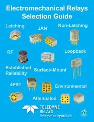
Series LB363/GLB363<br />
<strong>LoopBack</strong> <strong>Relay</strong><br />
Up to 12Gbps<br />
<strong>LoopBack</strong> <strong>Relay</strong><br />
LB363 Series<br />
GLB363 Series<br />
SERIES<br />
DESIGNATION<br />
LB363<br />
GLB363<br />
RELAY TYPE<br />
<strong>LoopBack</strong> <strong>Relay</strong>, Sensitive Coil<br />
<strong>LoopBack</strong> <strong>Relay</strong>, Ground Shield, Surface-Mount (Stub Leads), Sensitive Coil<br />
DESCRIPTION<br />
The <strong>LoopBack</strong> Series relay combines two DPDT<br />
electromechanical relays in one package that includes an<br />
internal bypass path for Automated Test Equipment (ATE)<br />
applications. The <strong>LoopBack</strong> combines the technology of two<br />
<strong>Teledyne</strong> RF/GRF300 Series relays which eliminates the need<br />
for external PCB traces in loop back test applications. This<br />
innovation results in superior signal integrity and RF<br />
performance, while taking minimal board space. The<br />
LB/GLB363 Series is designed for digital signaling application<br />
and provides excellent signal integrity up to 12 Gbps data<br />
rates.<br />
The <strong>LoopBack</strong> relay is available with two different internal<br />
paths: Through and AC Bypass. The Through version provides<br />
a loop back path across high performance contact material,<br />
while the AC Bypass Model adds a coupling capacitor across<br />
each loop back path. The internal in-line capacitors allow you<br />
to eliminate the footprints for external components, while<br />
performing AC bypass functions internal to the relay. The<br />
capacitors used feature excellent signal integrity as well as<br />
low loss high frequency performance.<br />
A typical loop-back load board application uses the Device<br />
Under Test (DUT) to test itself. In this method, the transmitter<br />
from the DUT is connected through a loop back path to the<br />
receiver of the DUT. The double pole design of the <strong>LoopBack</strong><br />
relay is perfectly suited for differential signaling, allowing<br />
relay component to provide transmit and receive signals and<br />
their inversions to the DUT or through the bypass path.<br />
The internal structure of the <strong>LoopBack</strong> relay reduces the<br />
number of discontinuities and shortens the signal path<br />
during loop back testing, providing lower insertion loss and<br />
higher signal integrity performance than two RF/GRF303<br />
Series relays. In the normally closed mode (de-energized) the<br />
<strong>LoopBack</strong> relay provides four normally closed contacts. When<br />
energized, the moving contacts are connected together<br />
across the loop back structure to provide two through paths.<br />
The normally closed contacts have similar performance to<br />
RF/GRF303 Series relays.<br />
In addition to the thru-hole mount, the <strong>LoopBack</strong> Series relay<br />
is available in through hole surface mount stub leads with a<br />
ground shield. The surface mount ground shield used in the<br />
stub lead provides improved high data rate and high<br />
frequency performance, as well as improved repeatability.<br />
Upon request, various ground pin configurations for through<br />
lead models are available.<br />
Temperature<br />
(Ambient)<br />
Vibration<br />
(General Note 1)<br />
Storage<br />
Operating<br />
ENVIRONMENTAL AND PHYSICAL SPECIFICATIONS<br />
–65°C to +125°C<br />
–55°C to +85°C<br />
10 g’s to 500 Hz<br />
Enclosure<br />
Shock<br />
(General Note 1)<br />
Hermetically sealed<br />
30 g’s,<br />
6ms half sine<br />
Weight LB363 0.16 oz. (4.53g) max. GLB363 0.18 oz. (5.10g) max.<br />
© 2012 TELEDYNE RELAYS (800) 284-7007 • www.teledynerelays.com LB363/GLB363 Page 1
Series LB363/GLB363<br />
<strong>LoopBack</strong> <strong>Relay</strong><br />
Up to 12Gbps<br />
SERIES LB363/GLB363<br />
TYPICAL RF Characteristics (See RF Notes on next page)<br />
0.00<br />
AC Bypass Path (thru Capacitor) - Insertion Loss<br />
5.00<br />
AC Bypass Path (thru Capacitor) - VSWR<br />
-0.50<br />
4.50<br />
Insertion Loss (dB)<br />
-1.00<br />
-1.50<br />
-2.00<br />
-2.50<br />
-3.00<br />
-3.50<br />
-4.00<br />
-4.50<br />
VSWR<br />
4.00<br />
3.50<br />
3.00<br />
2.50<br />
2.00<br />
1.50<br />
-5.00<br />
0.00 1.00 2.00 3.00 4.00 5.00 6.00 7.00 8.00<br />
Frequency (GHz)<br />
1.00<br />
0.00 1.00 2.00 3.00 4.00 5.00 6.00 7.00 8.00<br />
Frequency (GHz)<br />
AC Bypass Path (thru Capacitor) - Isolation<br />
0.00<br />
-10.00<br />
Isolation (dB)<br />
-20.00<br />
-30.00<br />
-40.00<br />
-50.00<br />
Normally Closed RF Performance<br />
-60.00<br />
0.00 1.00 2.00 3.00 4.00 5.00 6.00 7.00 8.00<br />
Frequency (GHz)<br />
Isolation Across Contacts (RF Note 4)<br />
Isolation Pole to Pole (RF Note 5)<br />
0<br />
0<br />
-10<br />
-10<br />
Isolation (dB)<br />
-20<br />
-30<br />
-40<br />
Isolation (dB)<br />
-20<br />
-30<br />
-40<br />
-50<br />
-50<br />
-60<br />
0 500 1000 1500 2000 2500 3000 3500 4000 4500 5000 5500 6000<br />
Frequency (MHz)<br />
-60<br />
0 500 1000 1500 2000 2500 3000 3500 4000 4500 5000 5500 6000<br />
Frequency (MHz)<br />
0<br />
Insertion Loss (RF Note 6)<br />
2.0<br />
VSWR (RF Note 6)<br />
Insertion Loss (dB)<br />
-0.2<br />
-0.4<br />
-0.6<br />
-0.8<br />
VSWR<br />
1.8<br />
1.6<br />
1.4<br />
1.2<br />
-1<br />
0 500 1000 1500 2000 2500 3000 3500 4000 4500 5000 5500 6000<br />
Frequency (MHz)<br />
1.0<br />
0 500 1000 1500 2000 2500 3000 3500 4000 4500 5000 5500 6000<br />
Frequency (MHz)<br />
LB363/GLB363 Page 2 SPECIFICATIONS ARE SUBJECT TO CHANGE WITHOUT NOTICE © 2012 TELEDYNE RELAYS
Series LB363/GLB363<br />
<strong>LoopBack</strong> <strong>Relay</strong><br />
Up to 12Gbps<br />
SERIES LB363/GLB363<br />
GENERAL ELECTRICAL SPECIFICATIONS (@ 25 ºC unless otherwise noted)<br />
Contact Arrangement Special (See Schematic on page 5)<br />
Rated Duty<br />
Continuous<br />
Contact Resistance<br />
0.200 Ω max. initial (measured 1/8" from the header)<br />
Contact Load Rating<br />
Contact Life Ratings<br />
Operate Time<br />
Release Time<br />
Insulation Resistance<br />
Dielectric Strength<br />
Resistive: 1Amp/28Vdc<br />
Low level: 10 to 50 μA, 10 to 50 mV<br />
5,000,000 cycles (typical) at low level<br />
4.0 mS max.<br />
3.0 mS max.<br />
1,000 MΩ min. between mutually isolated terminals<br />
350 Vrms (60 Hz) @ atmospheric pressure<br />
DETAILED ELECTRICAL SPECIFICATIONS (@25°C)<br />
BASE PART NUMBERS<br />
LB363-100-5<br />
GLB363-100-5<br />
LB363-100-12<br />
GLB363-100-12<br />
Coil Voltage, Nominal (Vdc) 5.0 12.0<br />
Coil Resistance (Ohms ±20%) 56 400<br />
Pick-up Voltage (Vdc max.) 3.6 9.0<br />
Coil Operating Power (mW) 450 360<br />
RF NOTES<br />
1. Test conditions: a. Fixture: .031" copper clad, reinforced PTFE, RT/duroid ® 6002 with SMA connectors.<br />
(RT/duroid ® is a registered trademark of Rogers Corporation.)<br />
b. Room ambient temperature.<br />
c. Terminals not tested were terminated with 50-ohm load.<br />
d. Contact signal level: –10 dBm.<br />
e. No. of test samples: 4.<br />
2. Data presented herein represents typical characteristics and is not intended for use as specification limits.<br />
3. Data is per pole, except for pole-to-pole data.<br />
4. Data is the average from readings taken on all open contacts.<br />
5. Data is the average from readings taken on poles with coil energized and de-energized.<br />
6. Data is the average from readings taken on all closed contacts.<br />
7. Test fixture effect de-embedded from frequency and time response data.<br />
© 2012 TELEDYNE RELAYS (800) 284-7007 • www.teledynerelays.com LB363/GLB363 Page 3
Series LB363/GLB363<br />
<strong>LoopBack</strong> <strong>Relay</strong><br />
Up to 12Gbps<br />
SERIES LB363/GLB363<br />
TYPICAL Single-Ended Signal Integrity Characteristics<br />
AC Bypass Path<br />
+100 mV<br />
0 V<br />
-100 mV<br />
0 ps 40 ps 80 ps 120 ps 160 ps 200 ps<br />
Eye Height Eye Width Jitter P-P<br />
254.3 mV 88.64 ps 8.89 ps<br />
SERIES LB363/GLB363<br />
TYPICAL Differential Signal Integrity Characteristics<br />
AC Bypass Path<br />
+200 mV<br />
0 V<br />
-200 mV<br />
0 ps 40 ps 80 ps 120 ps 160 ps 200 ps<br />
Eye Height Eye Width Jitter P-P<br />
492.1 mV 84.29 ps 15.55 ps<br />
LB363/GLB363 Page 4 SPECIFICATIONS ARE SUBJECT TO CHANGE WITHOUT NOTICE © 2012 TELEDYNE RELAYS
Series LB363/GLB363<br />
<strong>LoopBack</strong> <strong>Relay</strong><br />
Up to 12Gbps<br />
SERIES LB363<br />
OUTLINE DIMENSIONS<br />
12<br />
(Optional)<br />
(Optional)<br />
16<br />
18<br />
2<br />
14 4<br />
13 5<br />
(Optional)<br />
11<br />
9<br />
7<br />
CAPACITOR<br />
(Optional)<br />
U.S. PATENT PENDING<br />
NOTES:<br />
1. DIMENSIONS ARE IN INCHES. METRIC EQUIVALENTS<br />
(MILLIMETERS) ARE SHOWN IN [ X.XX ].<br />
2. TOLERANCE (UNLESS OTHERWISE SPECIFIED):<br />
±.010 INCH [±0.025 mm]<br />
SCHEMATIC - TERMINAL VIEW<br />
PIN NUMBERS ARE FOR REFERENCE<br />
ONLY, NOT MARKED ON RELAY<br />
CONTACT ARRANGEMENT<br />
N.C. SIDE (COILS DE-ENERGIZED):<br />
4PST, NORMALLY CLOSED<br />
N.O. SIDE (COILS ENERGIZED):<br />
DPST, NORMALLY OPEN,<br />
DOUBLE MAKE<br />
<strong>Teledyne</strong> Part Numbering System for <strong>LoopBack</strong> <strong>Relay</strong>s<br />
<strong>Relay</strong> Series<br />
Ground Pin (Optional)<br />
Y = Center Position<br />
Z = Center Position<br />
Blank = No ground pin<br />
LB363 YZ - 100 - 5<br />
Coil Voltage<br />
5 = 5V<br />
12 = 12V<br />
Capacitance<br />
100 = 100nF<br />
© 2012 TELEDYNE RELAYS (800) 284-7007 • www.teledynerelays.com LB363/GLB363 Page 5
Series LB363/GLB363<br />
<strong>LoopBack</strong> <strong>Relay</strong><br />
Up to 12Gbps<br />
SERIES GLB363<br />
OUTLINE DIMENSIONS<br />
RF GROUND SHIELD<br />
(SEE NOTE 3.)<br />
18<br />
16<br />
2<br />
14 4<br />
13 5<br />
11<br />
7<br />
9<br />
CAPACITOR<br />
NOTES:<br />
1. DIMENSIONS ARE IN INCHES. METRIC EQUIVALENTS<br />
(MILLIMETERS) ARE SHOWN IN [ X.XX ].<br />
2. TOLERANCE (UNLESS OTHERWISE SPECIFIED):<br />
±.010 INCH [±0.025 mm]<br />
3. FOR BEST RF PERFORMANCE, SOLDER BOTTOM OF RF<br />
GROUND SHIELD TO RF GROUND PLANE OF PC BOARD.<br />
SCHEMATIC - TERMINAL VIEW<br />
PIN NUMBERS ARE FOR REFERENCE<br />
ONLY, NOT MARKED ON RELAY<br />
CONTACT ARRANGEMENT<br />
N.C. SIDE (COILS DE-ENERGIZED):<br />
4PST, NORMALLY CLOSED<br />
N.O. SIDE (COILS ENERGIZED):<br />
DPST, NORMALLY OPEN,<br />
DOUBLE MAKE<br />
<strong>Teledyne</strong> Part Numbering System for <strong>LoopBack</strong> <strong>Relay</strong>s<br />
<strong>Relay</strong> Series<br />
GLB363 - 100 - 5<br />
Coil Voltage<br />
5 = 5V<br />
12 = 12V<br />
Capacitance<br />
100 = 100nF<br />
LB363/GLB363 Page 6 SPECIFICATIONS ARE SUBJECT TO CHANGE WITHOUT NOTICE © 2012 TELEDYNE RELAYS
Series LB363/GLB363<br />
<strong>LoopBack</strong> <strong>Relay</strong><br />
Up to 12Gbps<br />
SERIES LB363/GLB363<br />
APPLICATION NOTE<br />
DC TEST<br />
JITTER INSPECTION<br />
18<br />
16 2<br />
BIST<br />
LOOPBACK<br />
ATE<br />
14 4<br />
CAP 1 CAP 2<br />
13 5<br />
DUT<br />
AT SPEED<br />
CHARACTERIZATION<br />
11<br />
9<br />
7<br />
(Contacts shown in De-Energized position)<br />
DC TEST<br />
JITTER INSPECTION<br />
18<br />
16 2<br />
BIST<br />
LOOPBACK<br />
ATE<br />
14 4<br />
CAP 1 CAP 2<br />
13 5<br />
DUT<br />
AT SPEED<br />
CHARACTERIZATION<br />
11<br />
9<br />
7<br />
(Contacts shown in Energized position)<br />
NOTES:<br />
Coil Pins 9&18 are not polarity sensitive.<br />
<strong>Relay</strong> pins is bottom view.<br />
© 2012 TELEDYNE RELAYS (800) 284-7007 • www.teledynerelays.com LB363/GLB363 Page 7