GRF300-12 - Teledyne Relays
GRF300-12 - Teledyne Relays
GRF300-12 - Teledyne Relays

Create successful ePaper yourself
Turn your PDF publications into a flip-book with our unique Google optimized e-Paper software.
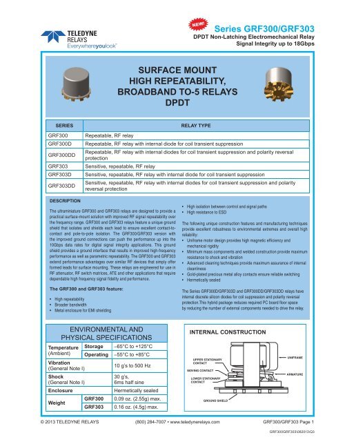
Series <strong>GRF300</strong>/GRF303<br />
DPDT Non-Latching Electromechanical Relay<br />
Signal Integrity up to 18Gbps<br />
SURFACE MOUNT<br />
HIGH REPEATABILITY,<br />
BROADBAND TO-5 RELAYS<br />
DPDT<br />
SERIES<br />
<strong>GRF300</strong><br />
<strong>GRF300</strong>D<br />
<strong>GRF300</strong>DD<br />
GRF303<br />
GRF303D<br />
GRF303DD<br />
RELAY TYPE<br />
Repeatable, RF relay<br />
Repeatable, RF relay with internal diode for coil transient suppression<br />
Repeatable, RF relay with internal diodes for coil transient suppression and polarity reversal<br />
protection<br />
Sensitive, repeatable, RF relay<br />
Sensitive, repeatable, RF relay with internal diode for coil transient suppression<br />
Sensitive, repeatable, RF relay with internal diodes for coil transient suppression and polarity<br />
reversal protection<br />
DESCRIPTION<br />
The ultraminiature <strong>GRF300</strong> and GRF303 relays are designed to provide a<br />
practical surface-mount solution with improved RF signal repeatability over<br />
the frequency range. <strong>GRF300</strong> and GRF303 relays feature a unique ground<br />
shield that isolates and shields each lead to ensure excellent contact-tocontact<br />
and pole-to-pole isolation. The <strong>GRF300</strong>/GRF303 version with<br />
the improved ground connections can push the performance up into the<br />
10Gbps data rates for digital signal integrity applications. This ground<br />
shield provides a ground interface that results in improved high-frequency<br />
performance as well as parametric repeatability. The <strong>GRF300</strong> and GRF303<br />
extend performance advantages over similar RF devices that simply offer<br />
formed leads for surface mounting. These relays are engineered for use in<br />
RF attenuator, RF switch matrices, ATE and other applications that require<br />
dependable high frequency signal fidelity and performance.<br />
The <strong>GRF300</strong> and GRF303 feature:<br />
• High repeatability<br />
• Broader bandwidth<br />
• Metal enclosure for EMI shielding<br />
• High isolation between control and signal paths<br />
• High resistance to ESD<br />
The following unique construction features and manufacturing techniques<br />
provide excellent robustness to environmental extremes and overall high<br />
reliability:<br />
• Uniframe motor design provides high magnetic efficiency and<br />
mechanical rigidity<br />
• Minimum mass components and welded construction provide maximum<br />
resistance to shock and vibration<br />
• Advanced cleaning techniques provide maximum assurance of internal<br />
cleanliness<br />
• Gold-plated precious metal alloy contacts ensure reliable switching<br />
• Hermetically sealed<br />
The Series <strong>GRF300</strong>D/GRF303D and <strong>GRF300</strong>DD/GRF303DD relays have<br />
internal discrete silicon diodes for coil suppression and polarity reversal<br />
protection.This hybrid package reduces required PC board floor space<br />
by reducing the number of external components needed to drive the relay.<br />
ENVIRONMENTAL AND<br />
PHYSICAL SPECIFICATIONS<br />
Temperature<br />
(Ambient)<br />
Vibration<br />
(General Note I)<br />
Shock<br />
(General Note I)<br />
Enclosure<br />
Weight<br />
Storage<br />
Operating<br />
<strong>GRF300</strong><br />
GRF303<br />
–65°C to +<strong>12</strong>5°C<br />
–55°C to +85°C<br />
10 g’s to 500 Hz<br />
30 g’s,<br />
6ms half sine<br />
Hermetically sealed<br />
0.09 oz. (2.55g) max.<br />
0.16 oz. (4.5g) max.<br />
INTERNAL CONSTRUCTION<br />
UPPER STATIONARY<br />
CONTACT<br />
MOVING CONTACT<br />
LOWER STATIONARY<br />
CONTACT<br />
GROUND SHIELD<br />
UNIFRAME<br />
ARMATURE<br />
© 2013 TELEDYNE RELAYS (800) 284-7007 • www.teledynerelays.com <strong>GRF300</strong>/GRF303 Page 1<br />
<strong>GRF300</strong>GRF303\082013\Q3
Series <strong>GRF300</strong>/GRF303<br />
DPDT Non-Latching Electromechanical Relay<br />
Signal Integrity up to 18Gbps<br />
SERIES <strong>GRF300</strong>/GRF303<br />
TYPICAL RF CHARACTERISTICS (See RF Notes)<br />
Isolation Across Contacts (RF Note 4)<br />
Isolation Pole to Pole (RF Note 5)<br />
0<br />
0<br />
-10<br />
-10<br />
Isolation (dB)<br />
-20<br />
-30<br />
-40<br />
Isolation (dB)<br />
-20<br />
-30<br />
-40<br />
-50<br />
-50<br />
-60<br />
-60<br />
0 500 1000 1500 2000 2500 3000 3500 4000 4500 5000 5500 6000<br />
Frequency (MHz)<br />
-70<br />
0 500 1000 1500 2000 2500 3000 3500 4000 4500 5000 5500 6000<br />
Frequency (MHz)<br />
0<br />
Insertion Loss (RF Note 6)<br />
2.0<br />
VSWR (RF Note 6)<br />
Insertion Loss (dB)<br />
-0.2<br />
-0.4<br />
-0.6<br />
VSWR<br />
1.8<br />
1.6<br />
1.4<br />
-0.8<br />
1.2<br />
-1<br />
0 500 1000 1500 2000 2500 3000 3500 4000 4500 5000 5500 6000<br />
Frequency (MHz)<br />
1.0<br />
0 500 1000 1500 2000 2500 3000 3500 4000 4500 5000 5500 6000<br />
Frequency (MHz)<br />
1.1<br />
<strong>GRF300</strong> Time Response (RF Note 6)<br />
0.9<br />
0.7<br />
90%<br />
37ps reference<br />
Volt<br />
0.5<br />
62.3ps propagation delay time<br />
0.3<br />
0.1<br />
51.3ps pulse rise time<br />
10%<br />
-0.1<br />
-100 0 100 200 300 400 500 600 700 800 900<br />
Time (ps)<br />
RF NOTES<br />
1. Test conditions: a. Fixture: .031” copper clad, reinforced PTFE, RT/duroid ® 6002 with SMA connectors.<br />
(RT/duroid ® is a registered trademark of Rogers Corporation.)<br />
b. RF ground shield is soldered to PCB RF ground plane.<br />
c. Room ambient temperature.<br />
d. Terminals not tested were terminated with 50-ohm load.<br />
e. Contact signal level: –10 dBm.<br />
f. No. of test samples: 2.<br />
2. Data presented herein represents typical characteristics and is not intended for use as specification limits.<br />
3. Data is per pole, except for pole-to-pole data.<br />
4. Data is the average from readings taken on all open contacts.<br />
5. Data is the average from readings taken on poles with coil energized and de-energized.<br />
6. Data is the average from readings taken on all closed contacts.<br />
7. Test fixture effect de-embedded from frequency and time response data.<br />
<strong>GRF300</strong>/GRF303 Page 2 SPECIFICATIONS ARE SUBJECT TO CHANGE WITHOUT NOTICE © 2013 TELEDYNE RELAYS<br />
<strong>GRF300</strong>GRF303\082013\Q3
Series <strong>GRF300</strong>/GRF303<br />
DPDT Non-Latching Electromechanical Relay<br />
Signal Integrity up to 18Gbps<br />
SERIES <strong>GRF300</strong> AND GRF303<br />
TYPICAL RF INSERTION LOSS REPEATABILITY CHARACTERISTICS<br />
(See RF Insertion Loss Repeatability Notes)<br />
REPEATABILITY CHARACTERISTICS <strong>GRF300</strong> RELAYS<br />
Normally Closed<br />
Normally Open<br />
% Total Number of Recorded Test Cycles<br />
100%<br />
80%<br />
60%<br />
40%<br />
20%<br />
0%<br />
0 0.02 0.04 0.06 0.08 0.1 0.<strong>12</strong> 0.14 0.16 0.18 0.2<br />
Repeatability (dB)<br />
% Total Number of Recorded Test Cycles<br />
100%<br />
80%<br />
60%<br />
40%<br />
20%<br />
0%<br />
0 0.02 0.04 0.06 0.08 0.1 0.<strong>12</strong> 0.14 0.16 0.18 0.2<br />
Repeatability (dB)<br />
REPEATABILITY CHARACTERISTICS GRF303 RELAYS<br />
Normally Closed<br />
Normally Open<br />
% Total Number of Recorded Test Cycles<br />
100%<br />
80%<br />
60%<br />
40%<br />
20%<br />
0%<br />
0 0.02 0.04 0.06 0.08 0.1 0.<strong>12</strong> 0.14 0.16 0.18 0.2<br />
Repeatability (dB)<br />
% Total Number of Recorded Test Cycles<br />
100%<br />
80%<br />
60%<br />
40%<br />
20%<br />
0%<br />
0 0.02 0.04 0.06 0.08 0.1 0.<strong>12</strong> 0.14 0.16 0.18 0.2<br />
Repeatability (dB)<br />
RF INSERTION LOSS REPEATABILITY NOTES<br />
1. Test conditions: a. Fixture: .031" copper clad, reinforced PTFE, RT/duroid ® 6002 with SMA connectors.<br />
(RT/duroid ® is a registered trademark of Rogers Corporation.)<br />
b. Test performed at room ambient temperature.<br />
c. Contact signal level: 20dBm.<br />
2. Data presented herein represents typical characteristics and is not intended for use as specification limits.<br />
3. Insertion loss repeatability measured over frequency range from 50MHz to 4GHz.<br />
© 2013 TELEDYNE RELAYS (800) 284-7007 • www.teledynerelays.com <strong>GRF300</strong>/GRF303 Page 3<br />
<strong>GRF300</strong>GRF303\082013\Q3
SERIES <strong>GRF300</strong>/GRF303<br />
TYPICAL RF REPEATABILITY PERFORMANCE (See RF Notes 1,2 and 3)<br />
1 Million Cycle Repeatability ±0.1 dB from DC to 3GHz<br />
Series <strong>GRF300</strong>/GRF303<br />
DPDT Non-Latching Electromechanical Relay<br />
Signal Integrity up to 18Gbps<br />
0.<strong>12</strong><br />
Typical repeatability of attenuation during life (normally open contacts)<br />
0.10<br />
.080<br />
±dB .060<br />
.040<br />
.020<br />
MAX<br />
X<br />
MIN.<br />
0 1 2 3 4 5 6 7 8 9 10<br />
Number of cycles X10 6<br />
0.<strong>12</strong><br />
Typical repeatability of insertion loss during life (normally closed contacts)<br />
0.10<br />
.080<br />
±dB .060<br />
MAX<br />
X<br />
MIN.<br />
.040<br />
.020<br />
0 1 2 3 4 5 6 7 8 9 10<br />
Number of cycles X10 6<br />
RF NOTES<br />
1. One million cycle repeatability data is based upon 396 observations with an average repeatability ±0.033 dB<br />
and a range of ±0.093 dB.<br />
2. Repeatability of attenuation values were obtained from tests conducted in a 20 dB attenuator network with a 0 dBm<br />
input signal.<br />
3. Relay operates at frequencies higher than 3 GHz with reduced RF performance characteristics.<br />
4. Curves were developed from tests performed on a 0.031" copper clad, reinforced PTFE circuit board at 20°C (ref).<br />
The unutilized contacts were terminated in 50 ohms; characteristic impedance of measuring equipment is 50 ohms.<br />
The relays were mounted flush to the circuit board ground plane without the relay header soldered to the ground<br />
plane.<br />
<strong>GRF300</strong>/GRF303 Page 4 SPECIFICATIONS ARE SUBJECT TO CHANGE WITHOUT NOTICE © 2013 TELEDYNE RELAYS<br />
<strong>GRF300</strong>GRF303\082013\Q3
Series <strong>GRF300</strong>/GRF303<br />
DPDT Non-Latching Electromechanical Relay<br />
Signal Integrity up to 18Gbps<br />
SERIES <strong>GRF300</strong>/GRF303<br />
GENERAL ELECTRICAL SPECIFICATIONS (@25°C)<br />
Contact Arrangement<br />
Rated Duty<br />
Contact Resistance<br />
Contact Load Rating<br />
Contact Life Ratings<br />
Coil Operating Power<br />
Operate Time<br />
Release Time<br />
Intercontact Capacitance<br />
Insulation Resistance<br />
Dielectric Strength<br />
Negative Coil Transient (Vdc)<br />
Diode P.I.V. (Vdc)<br />
2 Form C (DPDT)<br />
Continuous<br />
0.15 Ω max.<br />
Resistive: 1Amp/28Vdc<br />
Low level: 10 to 50 μA @ 10 to 50 mV<br />
10,000,000 cycles (typical) at low level<br />
<strong>GRF300</strong>-5: 500 mW @ nominal coil<br />
GRF303-5: 250 mW @ nominal coil<br />
<strong>GRF300</strong>: 4.0 mS max.<br />
GRF303: 6.0 mS max.<br />
<strong>GRF300</strong>: 3.0 mS max.<br />
GRF303: 3.0 mS max.<br />
0.4 pf typical<br />
1,000 MΩ min. between mutually isolated terminals<br />
350 Vrms (60 Hz) @ atmospheric pressure<br />
<strong>GRF300</strong>D/GRF303D,<br />
<strong>GRF300</strong>DD/GRF303DD<br />
<strong>GRF300</strong>D/GRF303D,<br />
<strong>GRF300</strong>DD/GRF303DD<br />
DETAILED ELECTRICAL SPECIFICATIONS (@25°C)<br />
BASE PART NUMBERS (<strong>GRF300</strong>, <strong>GRF300</strong>D,<br />
<strong>GRF300</strong>DD)<br />
<strong>GRF300</strong>-<strong>12</strong>: 370 mW @ nominal coil<br />
GRF303-<strong>12</strong>: 169 mW @ nominal coil<br />
<strong>GRF300</strong>D, <strong>GRF300</strong>DD: 4.0 mS max.<br />
GRF303D, GRF303DD: 7.5 mS max.<br />
<strong>GRF300</strong>-5<br />
<strong>GRF300</strong>D-5<br />
<strong>GRF300</strong>DD-5<br />
1.0 max<br />
100 min.<br />
<strong>GRF300</strong>-<strong>12</strong><br />
<strong>GRF300</strong>D-<strong>12</strong><br />
<strong>GRF300</strong>DD-<strong>12</strong><br />
Coil Voltage, Nominal (Vdc) 5.0 <strong>12</strong>.0<br />
<strong>GRF300</strong>, <strong>GRF300</strong>D 50 390<br />
Coil Resistance (Ohms<br />
±20%)<br />
<strong>GRF300</strong>DD (General<br />
39 390<br />
Note II)<br />
Coil Current (mAdc@ 25 Min. 93.2 25.6<br />
°C)(RF300DD Series) Max. <strong>12</strong>8.2 32.8<br />
Pick-up Voltage (Vdc<br />
max.)<br />
<strong>GRF300</strong>, <strong>GRF300</strong>D, 3.6 9.0<br />
<strong>GRF300</strong>DD 3.9 10.0<br />
BASE PART NUMBERS (RF303, RF303D,<br />
RF303DD)<br />
GRF303-5<br />
GRF303D-5<br />
GRF303DD-5<br />
GRF303-<strong>12</strong><br />
GRF303D-<strong>12</strong><br />
GRF303DD-<strong>12</strong><br />
Coil Voltage, Nominal (Vdc) 5.0 <strong>12</strong>.0<br />
GRF303, GRF303D 100 850<br />
Coil Resistance (Ohms<br />
±20%)<br />
GRF303DD (General<br />
64 850<br />
Note II)<br />
Coil Current (mAdc@ 25 Min. 56.8 11.7<br />
°C)(RF303DD Series) Max. 78.1 15.0<br />
Pick-up Voltage (Vdc<br />
max.)<br />
GRF303, GRF303D, 3.6 9.0<br />
GRF303DD 3.7 11.0<br />
© 2013 TELEDYNE RELAYS (800) 284-7007 • www.teledynerelays.com <strong>GRF300</strong>/GRF303 Page 5<br />
<strong>GRF300</strong>GRF303\082013\Q3
SERIES <strong>GRF300</strong> AND GRF303<br />
TYPICAL SIGNAL INTEGRITY CHARACTERISTICS @ 10 Gbps<br />
Series <strong>GRF300</strong>/GRF303<br />
DPDT Non-Latching Electromechanical Relay<br />
Signal Integrity up to 18Gbps<br />
i. Rt OFF = 31.1 pS.<br />
ii. Ft OFF = 32 pS.<br />
iii. V OFF = 511.95 mVpp.<br />
i. Rt ON = 30.2 pS.<br />
ii. Ft ON = 30.7 pS.<br />
iii. V ON = 5<strong>12</strong>.54 mV<br />
MEASUREMENTS NOTES<br />
Measurements were made using the Agilent AG86100 Digital Communication Analyzer with<br />
<strong>12</strong>GHz-pattern generator and 10GHz-clock source. The relay was mounted on an evaluation<br />
board. Two RF 3-foot long cables were used for measurements.<br />
Pattern Generator Settings<br />
• 2 31 –1 PRBS signal<br />
• 10Gbps data rate<br />
• Data amplitude of 500mVpp<br />
Oscilloscope Settings<br />
• Measurement threshold set to 20%–80%<br />
NRZ Eye/Mask mode measurements: rise time, fall time, eye ramp and bit rate<br />
0<br />
-10<br />
GRF303 Insertion Loss<br />
Insertion Loss S21 (dB)<br />
-20<br />
-30<br />
-40<br />
-50<br />
-60<br />
-70<br />
Notes:<br />
• Data measured on GRF303 mounted on RF PCB<br />
• PCB made of Rogers 6002, 0.076” trace width<br />
• Connectors used on PCB are from Pasternack PE4004<br />
• Data includes the effect of PCB and connectors<br />
• Test Temperature: Ambient Room<br />
• Test Date: 06/22/07<br />
NC Contact<br />
NO Contact<br />
-80<br />
0 1.5 3 4.5 6 7.5 9 10.5 <strong>12</strong> 13.5 15 16.5 18 19.5 21 22.5 24 25.5<br />
Frequency (GHz)<br />
Note: For Insertion Loss measurements in lower bandwidth (
Series <strong>GRF300</strong>/GRF303<br />
DPDT Non-Latching Electromechanical Relay<br />
Signal Integrity up to 18Gbps<br />
SERIES <strong>GRF300</strong>/GRF303<br />
OUTLINE DIMENSIONS<br />
.335 MAX<br />
(8.51)<br />
.031 (.79)<br />
REF<br />
.035 (.89)<br />
REF<br />
.315 MAX<br />
(8)<br />
(<strong>GRF300</strong>)<br />
.425 MAX<br />
(10.6)<br />
(GRF303)<br />
SEE NOTE 3<br />
.375 MAX<br />
(9.52)<br />
6 LEADS<br />
.035 REF<br />
(.89)<br />
U.S. PATENT PENDING<br />
.200 ±.010<br />
(5.98 ±0.25)<br />
DIA.<br />
(Viewed From Terminals)<br />
36° ±3° TYP<br />
SCHEMATIC DIAGRAMS<br />
9<br />
8<br />
7<br />
6<br />
1<br />
2<br />
3<br />
4<br />
9<br />
8<br />
7<br />
6<br />
1<br />
2<br />
3<br />
4<br />
9<br />
8<br />
7<br />
6<br />
1<br />
2<br />
3<br />
4<br />
<strong>GRF300</strong>/GRF303 <strong>GRF300</strong>D/GRF303D <strong>GRF300</strong>DD/GRF303DD<br />
NOTES:<br />
1. DIMENSIONS ARE IN INCHES, METRIC EQUIVALENTS SHOWN IN [ ].<br />
2. POSTITIONS 5 AND 10 ARE FOR UNINSULATED CASE GROUND OPTIONS.<br />
3. NO PROTRUSION BELOW BOTTOM OF HEADER WHEN GROUND PINS ARE INSTALLED<br />
4. TO ORDER THE CASE GROUND OPTION, AFTER THE SERIES DESIGNATOR, ADD “Y” TO THE PART NUMBER FOR POSITION<br />
5 OR “Z” TO THE PART NUMBER FOR POSITION 10.<br />
5. UNLESS OTHERWISE SPECIFIED, TOLERANCES ON DIMENSIONS ARE ± .010 INCH (0.025 MM)<br />
<strong>Teledyne</strong> Part Numbering System for <strong>GRF300</strong>/GRF303 <strong>Relays</strong><br />
Relay Series<br />
D = Internal diode for coil transient<br />
suppression<br />
DD = Internal diode for coil transient<br />
suppression and polarity reversal<br />
protection<br />
GRF303 D Y - 5<br />
Ground Pin Option<br />
(See Appendix A)<br />
Nominal Coil Voltage<br />
GENERAL NOTES<br />
I. <strong>Relays</strong> will exhibit no contact chatter in excess of 10 μsec or transfer in excess of 1 μsec.<br />
II. For reference only. Coil resistance not directly measureable at relay terminals due to internal series diode.<br />
© 2013 TELEDYNE RELAYS (800) 284-7007 • www.teledynerelays.com <strong>GRF300</strong>/GRF303 Page 7<br />
<strong>GRF300</strong>GRF303\082013\Q3
SERIES <strong>GRF300</strong>/GRF303<br />
TYPICAL SIGNAL INTEGRITY CHARACTERISTICS @ 10 Gbps<br />
Normally Closed (Typ.)<br />
Series <strong>GRF300</strong>/GRF303<br />
DPDT Non-Latching Electromechanical Relay<br />
Signal Integrity up to 18Gbps<br />
+130 mV<br />
0 V<br />
-130 mV<br />
0 ps 40 ps 80 ps <strong>12</strong>0 ps 160 ps<br />
Bit Rate Eye Height Eye Width Jitter P-P<br />
10 Gbps 237.6 mV 90.08 ps 9.33 ps<br />
Normally Open (Typ.)<br />
+130 mV<br />
0 V<br />
-130 mV<br />
0 ps 40 ps 80 ps <strong>12</strong>0 ps 160 ps<br />
Bit Rate Eye Height Eye Width Jitter P-P<br />
10 Gbps 255.2 mV 88.93 ps 8.89 ps<br />
PATTERN GENERATOR SETTINGS<br />
• 10 Gbps Random Pulse Pattern Generator<br />
• 2 31 - 1 PRBS signal<br />
• PRBS output of 300 mV P-P<br />
(nominal)<br />
• RF PCB effect (negligible) not removed from measurement<br />
• Data shown is typical of both poles<br />
<strong>GRF300</strong>/GRF303 Page 8 SPECIFICATIONS ARE SUBJECT TO CHANGE WITHOUT NOTICE © 2013 TELEDYNE RELAYS<br />
<strong>GRF300</strong>GRF303\082013\Q3
SERIES <strong>GRF300</strong>/GRF303<br />
TYPICAL SIGNAL INTEGRITY CHARACTERISTICS @ 18 Gbps<br />
Series <strong>GRF300</strong>/GRF303<br />
DPDT Non-Latching Electromechanical Relay<br />
Signal Integrity up to 18Gbps<br />
+150 mV<br />
0 V<br />
-150 mV<br />
0 ps 20 ps 40 ps 60 ps 80 ps<br />
100 ps<br />
Bit Rate Eye Height Eye Width Jitter P-P<br />
18 Gbps 185 mV 46.4 ps 10.44 ps<br />
PATTERN GENERATOR SETTINGS<br />
• 18 Gbps Random Pulse Pattern Generator<br />
• 2 31 - 1 PRBS signal<br />
• PRBS output of 300 mV P-P<br />
(nominal)<br />
• RF PCB effect (negligible) not removed from measurement<br />
• Data shown is typical of both poles<br />
© 2013 TELEDYNE RELAYS (800) 284-7007 • www.teledynerelays.com <strong>GRF300</strong>/GRF303 Page 9<br />
<strong>GRF300</strong>GRF303\082013\Q3