412K-12 - Teledyne Relays
412K-12 - Teledyne Relays
412K-12 - Teledyne Relays

Create successful ePaper yourself
Turn your PDF publications into a flip-book with our unique Google optimized e-Paper software.
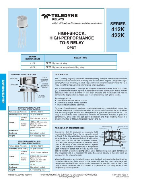
HIGH-SHOCK,HIGH-PERFORMANCETO-5 RELAYDPDTSERIES<strong>4<strong>12</strong>K</strong>422KSERIESDESIGNATION<strong>4<strong>12</strong>K</strong>422KDPDT high-shock relayRELAY TYPEDPDT high-shock magnetic-latching relayHIGH-PERFORMANCEINTERNAL CONSTRUCTIONUNI-FRAMEARMATUREUPPERSTATIONARYCONTACTLOWERSTATIONARYCONTACTMOVINGCONTACT<strong>4<strong>12</strong>K</strong> ENVIRONMENTAL ANDPHYSICAL SPECIFICATIONSTemperature (Ambient) –65°C to +<strong>12</strong>5°CVibration (General Note 1)ShockAccelerationEnclosureWeight(GeneralNote 1)(GeneralNote 4)30 g’s to 3000 Hz75 g’s, 6 msec, half-sine4000 g’s, 0.5 msec. axialplane, half-sine1000 g’s, 0.5 msec sideplanes, half-sine50 g’sHermetically sealed0.09 oz. (2.55g) max.422K ENVIRONMENTAL ANDPHYSICAL SPECIFICATIONSTemperature (Ambient) –65°C to +<strong>12</strong>5°CVibration (General Note 1)ShockAccelerationEnclosureWeight(GeneralNote 1)(GeneralNote 4)30 g’s to 3000 Hz100 g’s, 6 msec, half-sine2100 g’s, 0.5 msec. axialplane, half-sine750 g’s, 0.5 msec sideplanes, half-sine50 g’sHermetically sealed0.10 oz. (2.84g) max.DESCRIPTIONThe TO-5 relay, originally conceived and developed by <strong>Teledyne</strong>, has become one of theindustry standards for low-level switching from dry circuit to 1 ampere. Designed for highdensityPC board mounting, its small size and low coil power dissipation make the TO-5relay one of the most versatile subminiature relays available.The K Series high-shock TO-5 relays are designed to withstand shock levels up to 4000g’s, .5 millisecond duration. Special material selection and construction details provideassurance that critical elements of the relay structure and mechanism will not bepermanently displaced or damaged as a result of extremely high g level shocks.Typical applications:• Commercial avionics aircraft control• Commercial aircraft control systems• Transportation systems (rail/truck)By virtue of their inherently low intercontact capacitance and contact circuit losses, theK Series relays have proven to be excellent subminiature RF switches for applicationswith frequency ranges well into the UHF spectrum. A typical RF application for the TO-5relay is in handheld radio transceivers, wherein the combined features of good RFperformance, small size, low coil power dissipation and high reliability make it apreferred method of T-R switching (see Figure 1 and 2).PRINCIPLE OF OPERATION 422KEnergizing Coil B produces a magnetic fieldopposing the holding flux of the permanent magnetin Circuit B. As this net holding force decreases, theattractive force in the air gap of circuit A, which alsoresults from the flux of the permanent magnet,becomes great enough to break the armature free ofCore B, and snap it into a closed position againstCore A. The armature then remains in this positionupon removal of power from Coil B, but will snapMAGNETIC CIRCUIT BSOFT IRONCORE BSOFT IRONARMATUREPERMANENT MAGNETback to position B upon energizing Coil A. Since operation depends upon cancellationof a magnetic field, it is necessary to apply the correct polarity to the relay coils asindicated on the relay schematic.When latching relays are installed in equipment, the latch and reset coils should not bepulsed simultaneously. Coils should not be pulsed with less than rated coil voltage andthe pulse width should be a minimum of three times the specified operate time of therelay. If these conditions are not followed it is possible for the relay to be in themagnetically neutral position.COIL BMAGNETIC CIRCUIT ASOFT IRON FRAMECOIL ASOFT IRONCORE AAIR GAPSTATIONARYCONTACTMOVINGCONTACT©2003 TELEDYNE RELAYS SPECIFICATIONS ARE SUBJECT TO CHANGE WITHOUT NOTICE <strong>4<strong>12</strong>K</strong>/422K Page 1www.teledynerelays.com<strong>4<strong>12</strong>K</strong>/422K/<strong>12</strong>03/Q1
SERIES <strong>4<strong>12</strong>K</strong>/422KGENERAL ELECTRICAL SPECIFICATIONS (–65°C to +<strong>12</strong>5°C unless otherwise noted) (Notes 2 & 3)Contact ArrangementRated DutyContact ResistanceContact Load Ratings (DC)(See Fig. 3 for other DCresistive voltage/current ratings)Contact Load Ratings (AC)2 Form C (DPDT)Continuous<strong>4<strong>12</strong>K</strong>: 0.1 ohms max. before life; 0.2 ohms max. after life at 1A/28Vdc422K: 0.15 ohms max. before life; .225 ohms max after life at 1A/28VdcResistive:Inductive:Lamp:Low Level:Resistive:1 Amp/28Vdc200 mA/28Vdc (320 mH)100 mA/28Vdc10 to 50μA/10 to 50mV250 mA/115Vac, 60 and 400 Hz (Case not grounded)100 mA/115Vac, 60 and 400 Hz (Case grounded)10,000,000 cycles (typical) at low levelContact Life Ratings (Note 6) 1,000,000 cycles (typical) at 0.5A/28Vdc resistive100,000 cycles min. at all other loads specified aboveContact Overload Rating 2A/28Vdc Resistive (100 cycles min.)Contact Carry RatingContact factoryCoil Operating Power <strong>4<strong>12</strong>K</strong>: 500 mW typ. @ 25°C 422K: 290 mW typ. @ 25°COperate Time <strong>4<strong>12</strong>K</strong>: 2.0 msec max. 422K: 1.5 msec max.Release Time1.5 msec max. (<strong>4<strong>12</strong>K</strong> only)Contact Bounce1.5 msec max.Intercontact Capacitance 0.4 pf typicalInsulation Resistance10,000 megohms min. between mutually isolated terminalsDielectric Strength Atmospheric pressure: 500 Vrms/60Hz 70,000 ft.: <strong>12</strong>5 Vrms/60HzMinimum Operate Pulse4.5 msec width @ rated voltage (422K only)}measured 1/8" below header<strong>4<strong>12</strong>K</strong> SERIES RELAYDETAILED ELECTRICAL SPECIFICATIONS (–65°C to +<strong>12</strong>5°C unless otherwise noted) (Note 2)BASE PARTNUMBERS<strong>4<strong>12</strong>K</strong>-5 <strong>4<strong>12</strong>K</strong>-6 <strong>4<strong>12</strong>K</strong>-9 <strong>4<strong>12</strong>K</strong>-<strong>12</strong> <strong>4<strong>12</strong>K</strong>-18 <strong>4<strong>12</strong>K</strong>-26Coil Voltage (Vdc)Nom. 5.0 6.0 9.0 <strong>12</strong>.0 18.0 26.5Max. 5.8 8.0 <strong>12</strong>.0 16.0 24.0 32.0Coil Resistance (Ohms ±10% @25°C) 50 80 160 300 600 1350Pick-up Voltage (Vdc, Max.) 4.3 5.2 7.6 10.0 14.3 21.0Drop-out Voltage (Vdc)Min. 0.14 0.18 0.35 0.41 0.59 0.89Max. 2.5 3.2 4.9 6.5 10.0 13.0HIGH-PERFORMANCE422K SERIES RELAYDETAILED ELECTRICAL SPECIFICATIONS (–65°C to +<strong>12</strong>5°C unless otherwise noted) (Note 2)BASE PARTNUMBERS422K-5 422K-6 422K-9 422K-<strong>12</strong> 422K-18 422K-26Coil Voltage (Vdc)Nom. 5.0 6.0 9.0 <strong>12</strong>.0 18.0 26.5Max. 5.8 8.0 <strong>12</strong>.0 16.0 24.0 32.0Coil Resistance (Ohms ±10% @25°C) 61 <strong>12</strong>0 280 500 1130 2000Set & Reset Voltage (Vdc, Max.) 3.5 4.5 6.8 9.0 13.5 18.0<strong>4<strong>12</strong>K</strong>/422K Page 2 SPECIFICATIONS ARE SUBJECT TO CHANGE WITHOUT NOTICE ©2003 TELEDYNE RELAYSwww.teledynerelays.com<strong>4<strong>12</strong>K</strong>/422K/<strong>12</strong>03/Q1
SERIES <strong>4<strong>12</strong>K</strong>/422KPERFORMANCE CURVES(NOTE 2)dBTYPICAL RF PERFORMANCE0.1.2.3.4101.92201.22301.07401.02501.01601.0070 1.00.01 0.5 .1 .5 1.0INSERTION LOSSRETURN LOSS (VSWR)ISOLATION ACROSS CONTACTSISOLATION ACROSS POLESFREQUENCY (GHz)FIGURE 1 (<strong>4<strong>12</strong>K</strong>)VSWRdBTYPICAL RF PERFORMANCE0.1.2.3.4101.92201.22301.07401.02501.01601.0070 1.00.01 0.5 .1 .5 1.0INSERTION LOSSRETURN LOSS (VSWR)ISOLATION ACROSS CONTACTSISOLATION ACROSS POLESFREQUENCY (GHz)FIGURE 2 (422K)VSWRTYPICAL DC CONTACT RATING (RESISTIVE)300LOAD VOLTAGE (VDC)25020015010050HIGH-PERFORMANCEOUTLINE DIMENSIONS.370(9.40)DIA. MAX..335(8.51)DIA. MAX.0 0.1 0.2 0.3 0.4 0.5 0.6 0.7 0.8 0.9 1.0LOAD CURRENT (AMPS DC)FIGURE 3.035 (0.89)± .010 (0.25)TERMINAL LOCATIONS AND PIN NUMBERS (REF. ONLY)(Viewed from Terminals).031 (0.79)± .003 (0.08).035 (0.89)± .010 (0.25).031 (0.79)± .003 (0.08)9810<strong>12</strong>280 (7.11) MAX..200 (5.08)± .010 (.25) DIA. 36° ±3° TYP..200 (5.08)± .010 (.25) DIA. 36° ±3° TYP.76534WIRE LEAD: .75 (19.05) MIN.<strong>4<strong>12</strong>K</strong>422K.017 (.43)+.002 (.05)±.001 (.03)DIA.DIMENSIONS ARE SHOWN IN INCHES (MILLIMETERS)SCHEMATIC DIAGRAMSCOIL BGENERAL NOTES1. Relay contacts will exhibit no chatter in excess of 10 μsec ortransfer in excess of 1 μsec.2. “Typical” characteristics are based on available data and arebest estimates. No on-going verification tests are performed.3. Unless otherwise specified, parameters are initial values.4. Survival only — contact chatter may occur.COIL A<strong>4<strong>12</strong>K</strong>422KCONTACTS SHOWN IN POSITION RESULTINGWHEN COIL A LAST ENERGIZED.SCHEMATICS ARE VIEWED FROM TERMINALS©2003 TELEDYNE RELAYS SPECIFICATIONS ARE SUBJECT TO CHANGE WITHOUT NOTICE <strong>4<strong>12</strong>K</strong>/422K Page 3www.teledynerelays.com<strong>4<strong>12</strong>K</strong>/422K/<strong>12</strong>03/Q1
Appendix A: Spacer PadsPad designation andbottom view dimensionsØ.150[3.81](REF)“M4” Pad for TO-5Dim HMAXHeightFor use with the following:Dim. HMax.ER411TER4<strong>12</strong>, ER4<strong>12</strong>D, ER4<strong>12</strong>DD.295 (7.49)7<strong>12</strong>, 7<strong>12</strong>D, 7<strong>12</strong>TN,RF300, RF310, RF320.300 (7.62)ER420, ER422D, ER420DD, 421,ER421D, ER421DD, ER422, ER422D, .305 (7.75)ER422DD, 722, 722D, RF341ER431T, ER432T,ER432, ER432D, ER432DD.400 (10.16)732, 732D, 732TN, RF303, RF313,RF323.410 (10.41)RF3<strong>12</strong> .350 (8.89)ER411, ER411D, ER411DD .295 (7.49)Dim HMAXER431, ER431D, ER431DD .400 (10.16)RF311 .300 (7.62)“M4” Pad for TO-5RF331 .410 (10.41)“M4” Pad for Centigrid ® RF103 .420 (10.67)172, 172D .305 (7.75)ER114, ER114D, ER114DD,Dim HMAXJ114, J114D, J114DD.300 (7.62)ER134, ER134D, ER134DD,J134, J134D, J134DD.400 (10.16)RF100 .315 (8.00).156[3.96](REF)“M9” Pad for Centigrid ® A150 .305 (7.75)<strong>12</strong>2C, A152 .320 (8.13)Dim HER116C, J116C .300 (7.62)MAXER136C, J136C .400 (10.16)RF180 .325 (8.25).256[6.5](REF)Notes:1. Spacer pad material: Polyester lm.2. To specify an “M4” or “M9” spacer pad, refer to the mounting variants portion of the part numberingexample in the applicable datasheet.3. Dimensions are in inches (mm).4. Unless otherwise specied, tolerance is ± .010 (.25).5. Add 10 m to the contact resistance show in the datasheet.6. Add 0.01 oz. (0.25 g) to the weight of the relay assembly shown in the datasheet.© 2008 <strong>Teledyne</strong> <strong>Relays</strong> SPECIFICATIONS SUBJECT TO CHANGE WITHOUT NOTICE
Appendix A: Spreader PadsPad designation andbottom view dimensions.300[7.62].150[3.81].100[2.54].300[7.62].300[7.62].150[3.81].370 [9.4]MAX SQ.200[5.08]“M” Pad 5/ 6/.390 [9.91]SQ.300[7.62]“M2” Pad 7/ 8/.370 [9.4]MAX SQ.200[5.08].100[2.54].100[2.54].100[2.54].150[3.81].150[3.81].100[2.54].100[2.54]Dim HMAX.370[9.4]MINDim HMAX.130[3.3]Dim HMAX.370[9.4]MINHeightFor use with the following:Dim. HMax.ER411T, J411T, ER4<strong>12</strong>, ER4<strong>12</strong>DER4<strong>12</strong>DD, J4<strong>12</strong>, J4<strong>12</strong>D, J4<strong>12</strong>DD .388 (9.86)ER4<strong>12</strong>T, J4<strong>12</strong>T7<strong>12</strong>, 7<strong>12</strong>D, 7<strong>12</strong>TN .393 (9.99)ER431T, J431T, ER432, ER432DER432DD, J432, J432D, J432DD .493 (<strong>12</strong>.52)ER432T, J432T732, 732D, 732TN .503 (<strong>12</strong>.78)ER420, J420, ER420D, J420DER420DD, J420DD, ER421, J421.398 (10.11)ER421D, J421D, ER421DDJ422D, ER422DD, J422DD, 722ER411TER4<strong>12</strong>, ER4<strong>12</strong>D, ER4<strong>12</strong>DD.441 (11.20)J4<strong>12</strong>, J4<strong>12</strong>D, J4<strong>12</strong>DD7<strong>12</strong>, 7<strong>12</strong>D .451 (11.46)ER421, ER421D, ER421DD722, 732D.451 (11.46)ER431TER432, ER432D, ER432DD.546 (13.87)732, 732D .556 (14.<strong>12</strong>)ER411, ER411D, ER411DDER411TXER4<strong>12</strong>X, ER4<strong>12</strong>DX, ER4<strong>12</strong>DDXER4<strong>12</strong>TX.388 (9.86)7<strong>12</strong>X, 7<strong>12</strong>DX, 7<strong>12</strong>TNX .393 (9.99)ER420X, ER420DX, ER420DDXER421X, ER421DX, ER421DDX.398 (10.11)ER422X, ER422DXER422DDX, 722X, 722DDXER431, ER431D, ER431DDER431TXER432X, ER432DX, ER432DDXER432TX.493 (<strong>12</strong>.52)“M3” Pad 5/ 6/ 9/732X, 732DX, 732TNX .503 (<strong>12</strong>.78)Notes:1. Spreader pad material: Diallyl Phthalate.2. To specify an “M”, “M2” or “M3” spreader pad, refer to the mounting variants portion of the part number examplein the applicable datasheet.3. Dimensions are in inches (mm).4. Unless otherwise specied, tolerance is ± .010” (0.25).5/. Add 25 m to the contact resistance shown in the datasheet.6/. Add .01 oz. (0.25 g) to the weight of the relay assembly shown in the datasheet.7/. Add 50 m to the contact resistance shown in the datasheet.8/. Add 0.025 oz (0.71 g) to the weight of the relay assembly shown in the datasheet.9/. M3 pad to be used only when the relay has a center pin (e.g. ER411M3-<strong>12</strong>A, 722XM3-26.)(800) 284-7007 • www.teledynerelays.com +44 (0) <strong>12</strong>36 453<strong>12</strong>4 • www.teledyne-europe.com © 2008 <strong>Teledyne</strong> <strong>Relays</strong>.014[0.36](REF).014[0.36](REF)
Appendix A: Ground Pin PositionsØ.200[Ø5.08]"Z" POSITION"X" POSITION"Z" POSITIONØ.200[Ø5.08]36°±3°"Y" POSITION45°±3°"Y" POSITIONTO-5 <strong>Relays</strong>:ER411T, ER4<strong>12</strong>, ER4<strong>12</strong>T, ER420, ER421, ER422,ER431T, ER432, ER432T, 7<strong>12</strong>, 7<strong>12</strong>TN, 400H, 400K,400V, RF300, RF303, RF341, RF3<strong>12</strong>, RF310, RF313,RF320, RF323TO-5 <strong>Relays</strong>:ER411, ER431, RF311, RF331.100[2.54]"Y" POSITION"W" POSITION.100[2.54]"Y" POSITION.100[2.54]"Z" POSITION"Z" POSITION.050[1.27]"X" POSITION.100[2.54].100[2.54]"U" POSITION(ER116C and ER136C only).100[2.54]Centigrid® <strong>Relays</strong>:RF180, ER116C, <strong>12</strong>2C, ER136CCentigrid® <strong>Relays</strong>:RF100, RF103, ER114, ER134, 172Indicates ground pin positionIndicates glass insulated lead positionIndicates ground pin or lead positiondepending on relay typeNOTES1. Terminal views shown2. Dimensions are in inches (mm)3. Tolerances: ± .010 (±.25) unless otherwise specied4. Ground pin positions are within .015 (0.38) dia. of true position5. Ground pin head dia., 0.035 (0.89) ref: height 0.010 (0.25) ref.6. Lead dia. 0.017 (0.43) nom.© 2008 <strong>Teledyne</strong> <strong>Relays</strong> SPECIFICATIONS SUBJECT TO CHANGE WITHOUT NOTICE