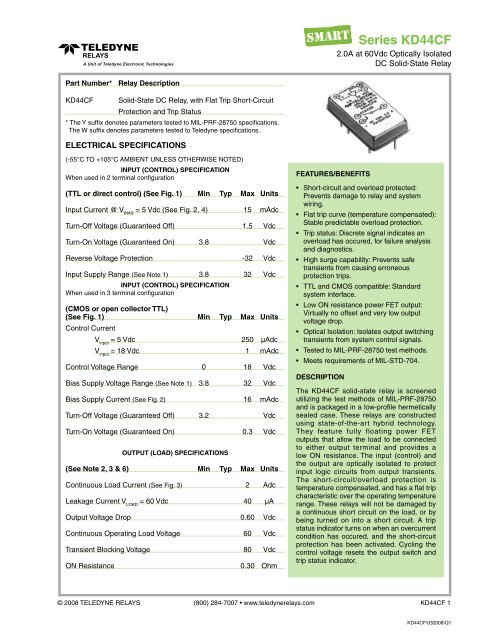
Series KD44CF - Teledyne Relays
Series KD44CF - Teledyne Relays
Series KD44CF - Teledyne Relays

You also want an ePaper? Increase the reach of your titles
YUMPU automatically turns print PDFs into web optimized ePapers that Google loves.
<strong>Series</strong> <strong>KD44CF</strong><br />
2.0A at 60Vdc Optically Isolated<br />
DC Solid-State Relay<br />
Part Number* Relay Description<br />
<strong>KD44CF</strong> Solid-State DC Relay, with Flat Trip Short-Circuit<br />
Protection and Trip Status<br />
* The Y suffix denotes parameters tested to MIL-PRF-28750 specifications.<br />
The W suffix denotes parameters tested to <strong>Teledyne</strong> specifications.<br />
ELECTRICAL SPECIFICATIONS<br />
(-55°C TO +105°C AMBIENT UNLESS OTHERWISE NOTED)<br />
INPUT (CONTROL) SPECIFICATION<br />
When used in 2 terminal configuration<br />
(TTL or direct control) (See Fig. 1) Min Typ Max Units<br />
Input Current @ V BIAS<br />
= 5 Vdc (See Fig. 2, 4) 15 mAdc<br />
Turn-Off Voltage (Guaranteed Off) 1.5 Vdc<br />
Turn-On Voltage (Guaranteed On) 3.8 Vdc<br />
Reverse Voltage Protection -32 Vdc<br />
Input Supply Range (See Note 1) 3.8 32 Vdc<br />
INPUT (CONTROL) SPECIFICATION<br />
When used in 3 terminal configuration<br />
(CMOS or open collector TTL)<br />
(See Fig. 1) Min Typ Max Units<br />
Control Current<br />
V input<br />
= 5 Vdc<br />
250 µAdc<br />
V input<br />
= 18 Vdc 1 mAdc<br />
Control Voltage Range 0 18 Vdc<br />
Bias Supply Voltage Range (See Note 1) 3.8 32 Vdc<br />
Bias Supply Current (See Fig. 2) 16 mAdc<br />
Turn-Off Voltage (Guaranteed Off) 3.2 Vdc<br />
Turn-On Voltage (Guaranteed On) 0.3 Vdc<br />
OUTPUT (LOAD) SPECIFICATIONS<br />
(See Note 2, 3 & 6) Min Typ Max Units<br />
Continuous Load Current (See Fig. 3) 2 Adc<br />
Leakage Current V LOAD<br />
= 60 Vdc 40 µA<br />
Output Voltage Drop 0.60 Vdc<br />
Continuous Operating Load Voltage 60 Vdc<br />
Transient Blocking Voltage 80 Vdc<br />
ON Resistance<br />
0.30 Ohm<br />
FEATURES/BENEFITS<br />
• Short-circuit and overload protected:<br />
Prevents damage to relay and system<br />
wiring.<br />
• Flat trip curve (temperature compensated):<br />
Stable predictable overload protection.<br />
• Trip status: Discrete signal indicates an<br />
overload has occured, for failure analysis<br />
and diagnostics.<br />
• High surge capability: Prevents safe<br />
transients from causing erroneous<br />
protection trips.<br />
• TTL and CMOS compatible: Standard<br />
system interface.<br />
• Low ON resistance power FET output:<br />
Virtually no offset and very low output<br />
voltage drop.<br />
• Optical Isolation: Isolates output switching<br />
transients from system control signals.<br />
• Tested to MIL-PRF-28750 test methods.<br />
• Meets requirements of MIL-STD-704.<br />
DESCRIPTION<br />
The <strong>KD44CF</strong> solid-state relay is screened<br />
utilizing the test methods of MIL-PRF-28750<br />
and is packaged in a low-profile hermetically<br />
sealed case. These relays are constructed<br />
using state-of-the-art hybrid technology.<br />
They feature fully floating power FET<br />
outputs that allow the load to be connected<br />
to either output terminal and provides a<br />
low ON resistance. The input (control) and<br />
the output are optically isolated to protect<br />
input logic circuits from output transients.<br />
The short-circuit/overload protection is<br />
temperature compensated, and has a flat trip<br />
characteristic over the operating temperature<br />
range. These relays will not be damaged by<br />
a continuous short circuit on the load, or by<br />
being turned on into a short circuit. A trip<br />
status indicator turns on when an overcurrent<br />
condition has occured, and the short-circuit<br />
protection has been activated. Cycling the<br />
control voltage resets the output switch and<br />
trip status indicator.<br />
© 2008 TELEDYNE RELAYS (800) 284-7007 • www.teledynerelays.com <strong>KD44CF</strong> 1<br />
<strong>KD44CF</strong>\032008\Q1
<strong>Series</strong> <strong>KD44CF</strong><br />
OUTPUT (LOAD) SPECIFICATIONS<br />
MECHANICAL SPECIFICATIONS<br />
(See Note 2, 3 & 6) Min Typ Max Units<br />
Turn-Off Time (See Fig. 6) 1 ms<br />
Turn-On Time (See Fig. 6) 5 ms<br />
Output Capacitance, 25 Vdc, 100 KHz 1000 pF<br />
Input to Output Capacitance 15 pF<br />
Dielectric Strength 1000 Vac<br />
Insulation Resistance @ 500 Vdc 10 9 Ohm<br />
Output Junction Temperature 130 °C<br />
@ I LOAD<br />
= maximum rated current<br />
Thermal Resistance Junction to Ambient(θ JA<br />
) 30 °C/W<br />
Thermal Resistance Junction to Case(θ JC<br />
) 10 °C/W<br />
STATUS OUTPUT SPECIFICATIONS<br />
Min Typ Max Units<br />
Status Supply Voltage 32 Vdc<br />
Status Leakage Current 15 Vdc 4 µA<br />
Status On Voltage @ 15 mA 0.4 Vdc<br />
Status Output TRUTH TABLE<br />
Status Output State Control Input Output (Load) State<br />
Off (High) Low On<br />
On (Low) Low Tripped<br />
Off (High) High Off<br />
On (Low) High Relay Malfunction<br />
ENVIRONMENTAL SPECIFICATIONS<br />
Min Typ Max Units<br />
Temperature Range<br />
Operating -55 +95 °C<br />
Storage -55 +125 °C<br />
Vibration (10–3000 Hz) 100 g<br />
Constant Acceleration 5000 g<br />
Enclosure: Hermetically Sealed DIP<br />
Leak Rate: 1 x 10 -8 CC/Sec Maximum<br />
Material: Header: Cold Rolled Steel<br />
Nickel Plated<br />
Pins: Copper Core<br />
Weight:<br />
20 grams<br />
Tolerance: XXX = ± .005<br />
DIMENSIONS ARE SHOWN IN INCHES (MILLI-<br />
METERS)<br />
PIN NO.<br />
BLOCK DIAGRAM<br />
PIN-OUTS<br />
FUNCTION<br />
1 CONTROL<br />
3 GND<br />
9 -V (OUT)<br />
12 +V (OUT)<br />
16 TRIP<br />
22 BIAS<br />
Shock, 0.5 ms 1500 g<br />
<strong>KD44CF</strong> 2 Specifications are subject to change without notice © 2008 TELEDYNE RELAYS<br />
<strong>KD44CF</strong>\032008\Q1
<strong>Series</strong> <strong>KD44CF</strong><br />
16<br />
14<br />
12<br />
10<br />
8<br />
6<br />
4<br />
2<br />
0<br />
TYPICAL INPUT CURRENT VS INPUT VOLTAGE<br />
FIGURE 2<br />
LOAD CURRENT DERATING CURVE<br />
FIGURE 3<br />
<strong>Series</strong> Resistance (Ohms)<br />
2000<br />
1500<br />
1000<br />
500<br />
0<br />
0 5 10 15 20 25 30 35<br />
Bias Supply Voltage (Volts)<br />
WIRING CONFIGURATIONS<br />
FIGURE 1<br />
SERIES LIMIT BIAS RESISTOR VS BIAS VOLTAGE<br />
FIGURE 4 (See Note 1)<br />
© 2008 TELEDYNE RELAYS (800) 284-7007 • www.teledynerelays.com <strong>KD44CF</strong> 3<br />
<strong>KD44CF</strong>\032008\Q1
<strong>Series</strong> <strong>KD44CF</strong><br />
TIME TO TRIP SECONDS<br />
TYPICAL OVERLOAD CURRENT VS TRIP TIME<br />
FIGURE 5<br />
TIME TO TRIP SECONDS<br />
PULSEWIDTHS ARE TAKEN AT 10% PEAK VALUE<br />
TYPICAL TRIP CURRENT CHARACTERISTICS<br />
FOR SHORT CIRCUIT CONDITIONS<br />
FIGURE 7<br />
OUTPUT TURN-ON AND OFF TIMING<br />
FIGURE 6<br />
NOTES:<br />
1. Control input is compatible with CMOS or open collector TTL (with pull up resistor). For bias voltages above 6V, a series resistor is<br />
required. Use the standard resistor value equal to or less than the value found in Figure 4.<br />
2. The rated input voltage is 5V for all tests unless otherwise specified.<br />
3. To calculate the maximum ON resistance for a given junction temperature, find the normalized ON resistance factor (NR) from<br />
Figure 5. Calculate the new ON resistance as follows:<br />
R (ON)<br />
= NR • R ON<br />
@ 25°C + 0.15<br />
4. Overload testing to the requirements of MIL-PRF-28750 is constrained to the limits imposed by the short circuit protection<br />
characteristics as defined in this specification. System series inductance for “shorted-load” mode of operation should be 30 µH<br />
maximum. Maximum repetition rate into a shorted load should not exceed 1 Hz.<br />
5. A status pull up resistor is required for proper operation of the status output. Determine the current (Iso) required by the status<br />
interface. Calculate the current (Is) through the status resistor such that the sink current through the status output does not<br />
exceed 15 mA.<br />
R STATUS<br />
= V - 0.4V<br />
STATUS<br />
I S<br />
6. Inductive loads should be diode suppressed. Input transitions should be ≤1 ms duration and the input drive should be a<br />
bounceless contact type.<br />
7. Input transitions should be ≤ 1 msec.<br />
<strong>KD44CF</strong> 4 Specifications are subject to change without notice © 2008 TELEDYNE RELAYS<br />
<strong>KD44CF</strong>\032008\Q1