Series KD44CF - Teledyne Relays
Series KD44CF - Teledyne Relays
Series KD44CF - Teledyne Relays

You also want an ePaper? Increase the reach of your titles
YUMPU automatically turns print PDFs into web optimized ePapers that Google loves.
<strong>Series</strong> <strong>KD44CF</strong><br />
TIME TO TRIP SECONDS<br />
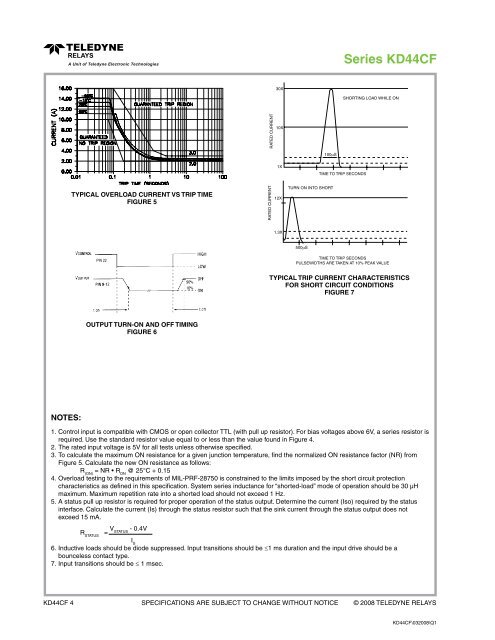
TYPICAL OVERLOAD CURRENT VS TRIP TIME<br />
FIGURE 5<br />
TIME TO TRIP SECONDS<br />
PULSEWIDTHS ARE TAKEN AT 10% PEAK VALUE<br />
TYPICAL TRIP CURRENT CHARACTERISTICS<br />
FOR SHORT CIRCUIT CONDITIONS<br />
FIGURE 7<br />
OUTPUT TURN-ON AND OFF TIMING<br />
FIGURE 6<br />
NOTES:<br />
1. Control input is compatible with CMOS or open collector TTL (with pull up resistor). For bias voltages above 6V, a series resistor is<br />
required. Use the standard resistor value equal to or less than the value found in Figure 4.<br />
2. The rated input voltage is 5V for all tests unless otherwise specified.<br />
3. To calculate the maximum ON resistance for a given junction temperature, find the normalized ON resistance factor (NR) from<br />
Figure 5. Calculate the new ON resistance as follows:<br />
R (ON)<br />
= NR • R ON<br />
@ 25°C + 0.15<br />
4. Overload testing to the requirements of MIL-PRF-28750 is constrained to the limits imposed by the short circuit protection<br />
characteristics as defined in this specification. System series inductance for “shorted-load” mode of operation should be 30 µH<br />
maximum. Maximum repetition rate into a shorted load should not exceed 1 Hz.<br />
5. A status pull up resistor is required for proper operation of the status output. Determine the current (Iso) required by the status<br />
interface. Calculate the current (Is) through the status resistor such that the sink current through the status output does not<br />
exceed 15 mA.<br />
R STATUS<br />
= V - 0.4V<br />
STATUS<br />
I S<br />
6. Inductive loads should be diode suppressed. Input transitions should be ≤1 ms duration and the input drive should be a<br />
bounceless contact type.<br />
7. Input transitions should be ≤ 1 msec.<br />
<strong>KD44CF</strong> 4 Specifications are subject to change without notice © 2008 TELEDYNE RELAYS<br />
<strong>KD44CF</strong>\032008\Q1