GRF300-12 - Teledyne Relays
GRF300-12 - Teledyne Relays
GRF300-12 - Teledyne Relays

You also want an ePaper? Increase the reach of your titles
YUMPU automatically turns print PDFs into web optimized ePapers that Google loves.
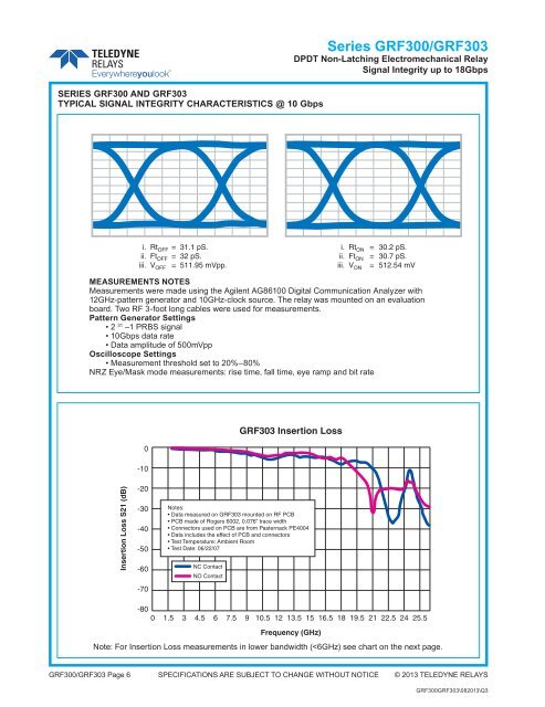
SERIES <strong>GRF300</strong> AND GRF303<br />
TYPICAL SIGNAL INTEGRITY CHARACTERISTICS @ 10 Gbps<br />
Series <strong>GRF300</strong>/GRF303<br />
DPDT Non-Latching Electromechanical Relay<br />
Signal Integrity up to 18Gbps<br />
i. Rt OFF = 31.1 pS.<br />
ii. Ft OFF = 32 pS.<br />
iii. V OFF = 511.95 mVpp.<br />
i. Rt ON = 30.2 pS.<br />
ii. Ft ON = 30.7 pS.<br />
iii. V ON = 5<strong>12</strong>.54 mV<br />
MEASUREMENTS NOTES<br />
Measurements were made using the Agilent AG86100 Digital Communication Analyzer with<br />
<strong>12</strong>GHz-pattern generator and 10GHz-clock source. The relay was mounted on an evaluation<br />
board. Two RF 3-foot long cables were used for measurements.<br />
Pattern Generator Settings<br />
• 2 31 –1 PRBS signal<br />
• 10Gbps data rate<br />
• Data amplitude of 500mVpp<br />
Oscilloscope Settings<br />
• Measurement threshold set to 20%–80%<br />
NRZ Eye/Mask mode measurements: rise time, fall time, eye ramp and bit rate<br />
0<br />
-10<br />
GRF303 Insertion Loss<br />
Insertion Loss S21 (dB)<br />
-20<br />
-30<br />
-40<br />
-50<br />
-60<br />
-70<br />
Notes:<br />
• Data measured on GRF303 mounted on RF PCB<br />
• PCB made of Rogers 6002, 0.076” trace width<br />
• Connectors used on PCB are from Pasternack PE4004<br />
• Data includes the effect of PCB and connectors<br />
• Test Temperature: Ambient Room<br />
• Test Date: 06/22/07<br />
NC Contact<br />
NO Contact<br />
-80<br />
0 1.5 3 4.5 6 7.5 9 10.5 <strong>12</strong> 13.5 15 16.5 18 19.5 21 22.5 24 25.5<br />
Frequency (GHz)<br />
Note: For Insertion Loss measurements in lower bandwidth (