LoopBack Relay Datasheet.indd - Teledyne Relays
LoopBack Relay Datasheet.indd - Teledyne Relays
LoopBack Relay Datasheet.indd - Teledyne Relays

Create successful ePaper yourself
Turn your PDF publications into a flip-book with our unique Google optimized e-Paper software.
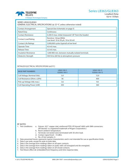
Series LB363/GLB363<br />
<strong>LoopBack</strong> <strong>Relay</strong><br />
Up to 12Gbps<br />
SERIES LB363/GLB363<br />
GENERAL ELECTRICAL SPECIFICATIONS (@ 25 ºC unless otherwise noted)<br />
Contact Arrangement Special (See Schematic on page 5)<br />
Rated Duty<br />
Continuous<br />
Contact Resistance<br />
0.200 Ω max. initial (measured 1/8" from the header)<br />
Contact Load Rating<br />
Contact Life Ratings<br />
Operate Time<br />
Release Time<br />
Insulation Resistance<br />
Dielectric Strength<br />
Resistive: 1Amp/28Vdc<br />
Low level: 10 to 50 μA, 10 to 50 mV<br />
5,000,000 cycles (typical) at low level<br />
4.0 mS max.<br />
3.0 mS max.<br />
1,000 MΩ min. between mutually isolated terminals<br />
350 Vrms (60 Hz) @ atmospheric pressure<br />
DETAILED ELECTRICAL SPECIFICATIONS (@25°C)<br />
BASE PART NUMBERS<br />
LB363-100-5<br />
GLB363-100-5<br />
LB363-100-12<br />
GLB363-100-12<br />
Coil Voltage, Nominal (Vdc) 5.0 12.0<br />
Coil Resistance (Ohms ±20%) 56 400<br />
Pick-up Voltage (Vdc max.) 3.6 9.0<br />
Coil Operating Power (mW) 450 360<br />
RF NOTES<br />
1. Test conditions: a. Fixture: .031" copper clad, reinforced PTFE, RT/duroid ® 6002 with SMA connectors.<br />
(RT/duroid ® is a registered trademark of Rogers Corporation.)<br />
b. Room ambient temperature.<br />
c. Terminals not tested were terminated with 50-ohm load.<br />
d. Contact signal level: –10 dBm.<br />
e. No. of test samples: 4.<br />
2. Data presented herein represents typical characteristics and is not intended for use as specification limits.<br />
3. Data is per pole, except for pole-to-pole data.<br />
4. Data is the average from readings taken on all open contacts.<br />
5. Data is the average from readings taken on poles with coil energized and de-energized.<br />
6. Data is the average from readings taken on all closed contacts.<br />
7. Test fixture effect de-embedded from frequency and time response data.<br />
© 2012 TELEDYNE RELAYS (800) 284-7007 • www.teledynerelays.com LB363/GLB363 Page 3