Grundfos Alldos DDI 209-222 Data Booklet - WES Dosing Products
Grundfos Alldos DDI 209-222 Data Booklet - WES Dosing Products
Grundfos Alldos DDI 209-222 Data Booklet - WES Dosing Products

Create successful ePaper yourself
Turn your PDF publications into a flip-book with our unique Google optimized e-Paper software.
GRUNDFOS ALLDOS DATA BOOKLET<br />
<strong>DDI</strong><br />
DIGITAL DOSING
Contents<br />
Features and benefits<br />
<strong>DDI</strong> <strong>209</strong> 3<br />
<strong>DDI</strong> <strong>222</strong> 4<br />
Performance range<br />
<strong>DDI</strong> 5<br />
<strong>DDI</strong> <strong>209</strong> with Plus3 6<br />
Identification<br />
Type key 7<br />
Functions<br />
Control variants 8<br />
Options 8<br />
Capacity control 9<br />
Control panel 9<br />
Menu 10<br />
Operating modes 12<br />
Other options 12<br />
Construction<br />
General description 15<br />
<strong>DDI</strong> <strong>209</strong> with manual deaeration valve 15<br />
<strong>DDI</strong> <strong>222</strong> 16<br />
<strong>DDI</strong> <strong>209</strong> with Plus3 system 17<br />
Functional principle of the Plus3 system 18<br />
Spring-loaded valves 18<br />
<strong>DDI</strong> with diaphragm leak detection 19<br />
Technical data<br />
Dimensions 20<br />
Performance data 24<br />
Suction lift 25<br />
Permissible viscosity 26<br />
Inlet and discharge pressures 27<br />
Permissible temperature range of the<br />
pumped medium 27<br />
Weights 28<br />
Electrical data 28<br />
Additional technical data 28<br />
Electronic functions 29<br />
Operating modes, additional data 30<br />
Pump selection<br />
<strong>DDI</strong> selection (0.4 to 150 l/h) 32<br />
Pumped media<br />
List of pumped media 35<br />
Further product documentation<br />
WebCAPS 36<br />
WinCAPS 37<br />
2
Features and benefits<br />
<strong>DDI</strong><br />
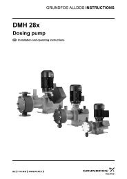
<strong>DDI</strong> <strong>209</strong><br />
DIGITAL DOSING<br />
up to 20 l/h<br />
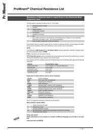
Fig. 1 <strong>DDI</strong> <strong>209</strong><br />
The difference is digital<br />
The <strong>Grundfos</strong> <strong>Alldos</strong> <strong>DDI</strong> range was created because<br />
accurate dosing demands precision. But it need not be<br />
hard work. These compact units combine perfect precision<br />
with a user interface that lets you set the dosing<br />
rate you want directly on the unit – without spending<br />
time on complicated calculations beforehand. Available<br />
materials include PVC, PVDF, polypropylene and stainless<br />
steel 1.4401.<br />
The <strong>DDI</strong> AR: Taking diaphragm dosing pumps to the<br />
next level<br />
The <strong>DDI</strong> AR series is the backbone of the overall <strong>DDI</strong><br />
range. Its innovative drive technology combines a powerful<br />
stepper motor with integrated contact signal control<br />
to bring you smoother, more accurate dosing. The<br />
user interface gives you a full range of options for customising<br />
the dosing process.<br />
Does the hard work for you<br />
The <strong>DDI</strong> range eliminates the need for extensive calculation<br />
work associated with other dosing equipment.<br />
You will not need to work out how many strokes per<br />
minute are necessary to give you the desired dosing<br />
rate – simply enter the figure you want in the user interface,<br />
and the <strong>DDI</strong> does the work for you.<br />
Smooth dosing through variable speed<br />
The <strong>Grundfos</strong> <strong>Alldos</strong> <strong>DDI</strong> never rushes things. It has an<br />
ingenious stepper motor that extends the discharge<br />
phase throughout the full period between suction<br />
phases. In other words, it automatically adjusts the dosing<br />
speed to provide the right amount of additive at all<br />
times. No jerky movements here – just smooth, even<br />
dosing.<br />
GrA3479<br />
Full stroke length at all times<br />
The <strong>Grundfos</strong> <strong>Alldos</strong> <strong>DDI</strong> uses a full stroke length every<br />
time, thereby eliminating potential disruptive factors<br />
such as gas build-up. Rather than adjusting the stroke<br />
length by shortening it to suit dosing demand, the<br />
<strong>Grundfos</strong> <strong>Alldos</strong> <strong>DDI</strong> carefully times each full stroke to<br />
ensure even concentrations of additive in your media.<br />
Turndown ratio 1:100<br />
The <strong>DDI</strong> range is designed to give you superior flexibility<br />
and accuracy with as few product variants as possible.<br />
That is why you can adjust dosing rates within a<br />
1:100 scale without any loss of dosing accuracy: the<br />
<strong>DDI</strong> series can dose additive in quantities down to<br />
0.025 l/h with perfect precision – and evidence of this<br />
precision can be provided at any time while the pump is<br />
running.<br />
Flow monitor checks for malfunctions - optional<br />
The unique flow monitor detects any dosing errors on<br />
both the suction and pressure sides and immediately<br />
emits an error message if anything is wrong. It can also<br />
check for excess pressure: Just enter the maximum<br />
counter pressure allowed (in bar) and leave everything<br />
to the <strong>DDI</strong>. If the pressure is exceeded, the pump stops.<br />
Fieldbus communication available<br />
The <strong>DDI</strong> is also available with a PROFIBUS DP interface.<br />
Switch-mode power supply<br />
<strong>DDI</strong> pumps can be used worldwide within the range of<br />
100-240 VAC, 50/60 Hz.<br />
Reliable dosing of viscous media<br />
When you wish to dose viscous media, many conventional<br />
dosing pumps struggle to maintain reliability. By<br />
contrast, the <strong>DDI</strong> series has a special "slow mode"<br />
function which decelerates the suction stroke. This<br />
maintains reliable dosing.<br />
Examples of applications<br />
• industrial and municipal water treatment<br />
• industrial cleaning<br />
• polymer feed<br />
• paper production/paper finishing<br />
• optical technology and chip production<br />
• chemical industry<br />
• Cleaning-In-Place (CIP) and disinfection<br />
• galvanic and surface treatment<br />
• air conditioning/water treatment in cooling towers<br />
• reverse-osmosis systems<br />
• semi-conductor industry.<br />
3
Features and benefits<br />
<strong>DDI</strong><br />
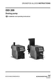
<strong>DDI</strong> <strong>222</strong><br />
DIGITAL DOSING<br />
up to 150 l/h<br />
Compact design<br />
<strong>DDI</strong> pumps are smaller and quieter than conventional<br />
pumps in their class, making them easy to install anywhere.<br />
Order your <strong>DDI</strong> with the control and display<br />
interface on the side or front as you wish.<br />
Full stroke length every time<br />
The <strong>DDI</strong> series use a full stroke length every time - a<br />
feature unique to <strong>Grundfos</strong> <strong>Alldos</strong> dosing pumps. Each<br />
stroke is carefully timed to bring you even concentrations<br />
in the system and optimum priming throughout the<br />
entire operating range.<br />
Brushless DC motor<br />
The drive solution used in the <strong>DDI</strong> series ensures very<br />
smooth, continuous dosing even as it keeps energy<br />
consumption at a record low.<br />
Fig. 2 <strong>DDI</strong> <strong>222</strong><br />
The <strong>DDI</strong> series is firmly established on the dosing pump<br />
market with its combination of innovative drive technology<br />
and integrated microelectronics. Users appreciate<br />
how they can simply enter the required dosing rate in<br />
litres per hour and let the <strong>DDI</strong> handle the rest.<br />
Flow monitor checks for malfunctions (optional)<br />
The unique flow monitor detects any dosing errors on<br />
both the suction and pressure sides and immediately<br />
emits an error message if anything is wrong. It can also<br />
check for excess pressure: Just enter the maximum<br />
counter pressure allowed (in bar) and leave everything<br />
to the <strong>DDI</strong>. If the pressure is exceeded, the pump stops.<br />
Double diaphragm for optimum process reliability<br />
Some processes must never be interrupted - not even<br />
in the event of a diaphragm rupture. The <strong>DDI</strong> is<br />
equipped with a double diaphragm system. If the diaphragm<br />
fails, the <strong>DDI</strong> will continue dosing thanks to the<br />
protective diaphragm.<br />
Diaphragm leak detection (optional)<br />
If the pump is supplied with diaphragm leak detection,<br />
a differential pressure sensor will send an error signal<br />
as notification to replace the diaphragm.<br />
Turndown ratio of 1:800<br />
The <strong>DDI</strong> <strong>222</strong> has a turndown ratio ten times better than<br />
that of conventional equipment. This allows us to create<br />
a complete pump series with just one motor, one gearing<br />
system, and two pump head sizes. You get the precision<br />
you want every time - and need only a minimum<br />
of spare parts and storage capacity.<br />
GrA3486<br />
Anti-cavitation function<br />
The "slow mode" settings systematically reduce the<br />
suction stroke so that difficult, viscous media are dosed<br />
with smooth precision. When set at 60% of the maximum<br />
dosing rate, the <strong>DDI</strong> can dose media with a viscosity<br />
of up to 1,000 [mPa s] at 40%, it will handle<br />
extremely viscous media up to 2600 [mPa s]. You no<br />
longer need external dilution or treatment systems, but<br />
can dose chemicals directly and with no waste.<br />
Fieldbus communication available<br />
The <strong>DDI</strong> is also available with a PROFIBUS DP interface.<br />
Switch-mode power supply<br />
<strong>DDI</strong> pumps can be used worldwide within the range of<br />
100-240 VAC, 50/60 Hz.<br />
Examples of applications<br />
• industrial and municipal water treatment<br />
• industrial cleaning<br />
• polymer feed<br />
• paper production/paper finishing<br />
• optical technology and chip production<br />
• chemical industry<br />
• Cleaning-In-Place (CIP) and disinfection<br />
• galvanic and surface treatment<br />
• air conditioning/water treatment in cooling towers<br />
• reverse-osmosis systems<br />
• semi-conductor industry.<br />
4
Performance range<br />
<strong>DDI</strong><br />
<strong>DDI</strong><br />
p<br />
[bar]<br />
16<br />
<strong>DDI</strong><br />
14<br />
12<br />
10<br />
8<br />
6<br />
4<br />
2<br />
1 2 3 4<br />
5 6 7 8<br />
0<br />
0.2 0 0.3 0.4 0.6 0.8 1 2 3 4 6 8 10 15 20 30 40 60 80 100 150<br />
Q [l/h]<br />
TM03 8264 0907<br />
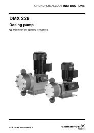
Fig. 3 Performance range, <strong>DDI</strong><br />
Pos. Pump Model<br />
1 <strong>DDI</strong> 0.4-10 <strong>209</strong><br />
2 <strong>DDI</strong> 2.2-16 <strong>209</strong><br />
3 <strong>DDI</strong> 2.5-10 <strong>209</strong><br />
4 <strong>DDI</strong> 6.0-10 <strong>209</strong><br />
5 <strong>DDI</strong> 13.8-4 <strong>209</strong><br />
6 <strong>DDI</strong> 20-3 <strong>209</strong><br />
7 <strong>DDI</strong> 60-10 <strong>222</strong><br />
8 <strong>DDI</strong> 150-4 <strong>222</strong><br />
5
Performance range<br />
<strong>DDI</strong><br />
<strong>DDI</strong> <strong>209</strong> with Plus 3<br />
p<br />
[bar]<br />
16<br />
<strong>DDI</strong> Plus 3<br />
14<br />
12<br />
10<br />
8<br />
6<br />
4<br />
2<br />
1 2 3<br />
4<br />
0<br />
0.2 0 0.3 0.4 0.5 0.6 0.8 1 2 3 4 5 6<br />
Q [l/h]<br />
TM03 8263 0907<br />
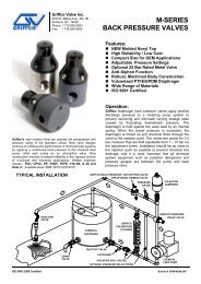
Fig. 4 Performance range, <strong>DDI</strong> <strong>209</strong> with Plus 3<br />
Pos. Pump Model<br />
1 <strong>DDI</strong> 0.4-10 <strong>209</strong> with Plus 3<br />
2 <strong>DDI</strong> 2.2-16 <strong>209</strong> with Plus 3<br />
3 <strong>DDI</strong> 2.5-10 <strong>209</strong> with Plus 3<br />
4 <strong>DDI</strong> 6.0-10 <strong>209</strong> with Plus 3<br />
6
Identification<br />
<strong>DDI</strong><br />
Type key<br />
Example: <strong>DDI</strong> 2- 16 AR PVC /V /G -F -3 1 3 B1 B<br />
Type range<br />
Mains plug<br />
<strong>DDI</strong> F EU (Schuko)<br />
Size<br />
Control variant<br />
B<br />
I<br />
E<br />
X<br />
USA, Canada<br />
Australia, New Zealand, Taiwan<br />
Switzerland<br />
Without plug<br />
AR Standard<br />
AF AR with flow monitor<br />
Connection, suction/discharge<br />
AP AR with PROFIBUS B6 Pipe, 4/6 mm<br />
APF AR with flow monitor and PROFIBUS 3 Tube, 4/6 mm<br />
A5 Tube, 5/8 mm<br />
<strong>Dosing</strong> head variant<br />
4 Tube, 6/9 mm<br />
PP Polypropylene 6 Tube, 9/12 mm<br />
PV PVDF (polyvinylidene fluoride) Q Tube, 19/27 mm<br />
PVC Polyvinyl chloride C4 Tube, 1/8" / 1/4"<br />
SS Stainless steel, DIN 1.4401 R Tube, 1/4" / 3/8"<br />
PP-P3 PP + Plus 3 S Tube, 3/8" / 1/2"<br />
PVC-P3 PVC + Plus 3 A Threaded, Rp 1/4<br />
PP-L PP + Integrated diaphragm leak detection A1 Threaded, Rp 3/4, female<br />
PV-L PV + Integrated diaphragm leak detection V Threaded, 1/4" NPT<br />
PVC-L PVC + Integrated diaphragm leak detection A9 Threaded, 1/2" NPT, male<br />
SS-L SS + Integrated diaphragm leak detection A3 Threaded, 3/4" NPT, female<br />
Gasket material<br />
A7<br />
B1<br />
Threaded, 3/4" NPT, male<br />
Tube, 6/12 mm/cementing diameter,<br />
12 mm<br />
E EPDM B2<br />
Tube, 13/20 mm/cementing diameter,<br />
25 mm<br />
V FKM B3 Welding diameter, 16 mm<br />
T PTFE B4 Welding diameter, 25 mm<br />
Valve ball material<br />
Valve type<br />
C Ceramic 1 Standard<br />
G Glass<br />
Spring-loaded<br />
2 0.05 bar suction opening pressure<br />
T PTFE<br />
0.05 bar discharge opening pressure<br />
SS Stainless steel, DIN 1.4401<br />
Spring-loaded<br />
3 0.05 bar suction opening pressure<br />
Control panel position<br />
0.8 bar discharge opening pressure<br />
Spring-loaded discharge<br />
4<br />
F Front-mounted<br />
0.8 bar discharge opening pressure<br />
S Side-mounted<br />
5 For abrasive media (SS only)<br />
T Top-mounted<br />
6<br />
Spring-loaded discharge<br />
(DN 20, balls in SS, DIN 1.4401)<br />
0.8 bar discharge opening pressure<br />
Supply voltage<br />
3 1 x 100-240 V, 50/60 Hz<br />
I 24 VDC<br />
7
Functions<br />
<strong>DDI</strong><br />
Control variants<br />
Control variants<br />
Features<br />
AR AF AP APF<br />
Flow monitor • •<br />
PROFIBUS communication • •<br />
Fig. 5 <strong>DDI</strong> <strong>209</strong> Fig. 6 <strong>DDI</strong> <strong>222</strong><br />
Options<br />
Pump<br />
Standard<br />
AR with<br />
flow monitor<br />
Control variants<br />
AR with PROFIBUS<br />
AR with<br />
flow monitor and<br />
PROFIBUS<br />
AR AF AP APF<br />
<strong>DDI</strong> 0.4-10 • • • •<br />
<strong>DDI</strong> 2.2-16 • • • •<br />
<strong>DDI</strong> 2.5-10 • • • •<br />
<strong>DDI</strong> 6.0-10 • • • •<br />
<strong>DDI</strong> 13.8-4 • • • •<br />
<strong>DDI</strong> 20-3 • • • •<br />
<strong>DDI</strong> 60-10 • • • •<br />
<strong>DDI</strong> 150-4 • • • •<br />
Pump heads<br />
Additional options<br />
Pump<br />
AR + Plus 3 AF + Plus 3 Diaphragm leak<br />
Spring-loaded<br />
Top control panel<br />
detection<br />
valves (HV)<br />
24 V DC motor<br />
<strong>DDI</strong> 0.4-10 • • • • • •<br />
<strong>DDI</strong> 2.2-16 • • • • • •<br />
<strong>DDI</strong> 2.5-10 • • • • • •<br />
<strong>DDI</strong> 6.0-10 • • • • • •<br />
<strong>DDI</strong> 13.8-4 • • • •<br />
<strong>DDI</strong> 20-3 • • • •<br />
<strong>DDI</strong> 60-10 • •<br />
<strong>DDI</strong> 150-4 • •<br />
8
Functions<br />
<strong>DDI</strong><br />
Capacity control<br />
The stepper motor of the <strong>DDI</strong> <strong>209</strong> provides full control<br />
of the stroke speed.<br />
The <strong>DDI</strong> <strong>222</strong> has an EC motor (brushless DC motor)<br />
and electronic power control. See page 24.<br />
As shown in the figure below, the duration of each suction<br />
stroke is constant (while the duration of each discharge<br />
stroke varies according to the set capacity.<br />
This has many advantages:<br />
• The full stroke length reduces gas build-up in the<br />
dosing head.<br />
• Even and constant dosing ensures an optimum mixing<br />
ratio at the injection point.<br />
• Significant reduction of pressure surges prevents<br />
mechanical stress on diaphragm, tubes, connections<br />
and other dosing parts.<br />
• The installation is less affected by long suction and<br />
discharge lines.<br />
• <strong>Dosing</strong> of highly viscous and volatile media is easier.<br />
Capacity setting<br />
100%<br />
Discharge<br />
Duration<br />
Suction<br />
50%<br />
Discharge<br />
Duration<br />
Suction<br />
10%<br />
Discharge<br />
Suction<br />
Duration<br />
TM03 2074 3505<br />
Fig. 7 Relation between discharge stroke speed and capacity<br />
Control panel<br />
Fig. 8 <strong>DDI</strong> control panel<br />
TM03 4455 2106<br />
Legend<br />
Pos.<br />
1<br />
2<br />
3<br />
Component<br />
Mode (light-emitting diode):<br />
• Red light indicates that the pump has stopped.<br />
• Green light indicates that the pump has started; the light is<br />
briefly off during a suction stroke.<br />
• Yellow light indicates that the pump has been switched off<br />
remotely.<br />
• Red light is flashing in case of an error signal.<br />
• Light is off when the pump is in menu mode.<br />
Start/stop (button):<br />
• Press the button to start and stop the pump.<br />
Menu (button):<br />
• Press the button to switch between operating modes.<br />
Down/Up (button):<br />
4<br />
• Press the button to change the values in the display.<br />
5 LCD display<br />
9
Functions<br />
<strong>DDI</strong><br />
Menu<br />
Menu, first level<br />
Pump is not running<br />
(indicator light is red)<br />
Pump is running<br />
(indicator light is green)<br />
Manual control<br />
Set dosing rate (percentage of<br />
maximum dosing rate).<br />
Contact signal control<br />
Set dosing amount per stroke (setting<br />
range: 2% to 400% of the volume per<br />
stroke).<br />
Analog control<br />
0-20 mA<br />
<strong>Dosing</strong> rate proportional to current signal<br />
< 0.2 mA Pump stops.<br />
0.2-20 mA <strong>Dosing</strong> rate proportional to current signal.<br />
≥ 20 mA Continuous operation at maximum dosing<br />
rate.<br />
Analog control<br />
4-20 mA<br />
<strong>Dosing</strong> rate proportional to current signal<br />
< 2 mA Fault signal switches on.<br />
Display -> "ERROR".<br />
LED flashes red.<br />
< 4.2 mA Pump stops.<br />
4.2-20 mA <strong>Dosing</strong> rate proportional to current signal.<br />
≥ 20 mA Continuous operation at maximum dosing<br />
rate.<br />
TM03 4453 2106<br />
Fig. 9 Menu, first level<br />
10
Functions<br />
<strong>DDI</strong><br />
Menu, second level<br />
See the pump installation and operating instructions for<br />
a detailed overview and instructions for navigating the<br />
menu.<br />
Pump is running<br />
(indicator light is green)<br />
Pump is not running<br />
(indicator light is red)<br />
Press for 3 seconds<br />
Second menu level<br />
Set code 111<br />
• calibration<br />
• flow on/off<br />
• pressure control<br />
• memory on/off<br />
• analog weighting<br />
• batch<br />
•timer<br />
•PROFIBUS<br />
• slow mode<br />
• display reset of total<br />
• dosing capacity<br />
• display of operating hours.<br />
TM03 4454 2106<br />
Fig. 10 Menu, second level<br />
Menu, third level<br />
The third level is for setting the pump type and the dosing<br />
flow measuring unit (l/h or gal/h) as well as inputs<br />
and outputs.<br />
11
Functions<br />
<strong>DDI</strong><br />
Operating modes<br />
Manual control<br />
In manual control mode, set the flow rate in the display.<br />
Pulse control<br />
For each pulse received at the contact input of the<br />
pump (for example from a water meter with reed contact<br />
output), the pump doses the set quantity. The<br />
memory can store a maximum of 65,000 pulses for later<br />
processing.<br />
Analog control<br />
The dosed quantity is proportional to the current input<br />
signal of 0-20 mA or 4-20 mA.<br />
Batch mode<br />
In batch mode, a defined batch quantity is dosed with a<br />
defined flow. The dosing of a batch can be triggered<br />
manually and by pulse.<br />
Timer batch<br />
The set batch quantity is dosed with a preset interval.<br />
Slow mode<br />
In slow mode, the pumps slow down the suction stroke.<br />
This reduces cavitation when dosing viscous media.<br />
Slow mode can be activated in any operating mode.<br />
Other options<br />
A system for detecting liquid behind the diaphragm can<br />
be installed as an option. In the event of a leak or diaphragm<br />
failure, the controller can trigger an alarm and/<br />
or switch off the pump.<br />
Pumps with diaphragm leak detection have a special<br />
dosing head flange for inserting an opto-electronic sensor.<br />
The diaphragm leak detection sensor is installed<br />
from factory.<br />
The opto-electronic sensor contains these elements:<br />
• infrared transmitter<br />
• infrared receiver.<br />
Leak-detection opto-sensor<br />
In case of a leak in the diaphragm, these events take<br />
place:<br />
• The medium penetrates the dosing head flange.<br />
• Light refraction changes.<br />
• The sensor emits a signal.<br />
The electronics switch two contacts, which can be<br />
used, for example, to trigger an alarm signal or to<br />
switch off the pump.<br />
.<br />
Normal mode<br />
Discharge<br />
Duration<br />
Suction<br />
Slow mode<br />
Discharge<br />
Duration<br />
Suction<br />
Fig. 11 Slow mode vs. normal operation<br />
TM03 4456 2106<br />
Fig. 12 Leak-detection opto-sensor<br />
Tank-level control<br />
The pumps feature two-stage tank-empty signal. This<br />
requires a separate tank-empty sensor not included<br />
with the pump.<br />
Flow monitor (option)<br />
This unit monitors the dosing process and emits a pulse<br />
for each suction stroke. The unit is only suitable for<br />
aqueous media with a maximum viscosity of 5 [mPa s].<br />
TM03 3626 0506<br />
12
Functions<br />
<strong>DDI</strong><br />
Electronic lock<br />
The pump can be locked to prevent it from being<br />
stopped manually. When this function is activated<br />
(service level), the pump starts running with the current<br />
settings and cannot be stopped by means of the [Start/<br />
Stop] button.<br />
It is still possible to acknowledge error messages by<br />
pressing [Start/Stop].<br />
To stop the pump when the electronic lock is activated,<br />
do as follows:<br />
• If the remote switching on/off is active (the plug is<br />
inserted), switch off the pump remotely.<br />
• Disconnect the pump from the power supply.<br />
Calibration<br />
The dosing flow display is factory-set to an operating<br />
counter pressure of 3 bar. Calibration can be used to<br />
set the pump flow to the current operating conditions.<br />
Remote switching on/off<br />
The pump can be switched off remotely from a control<br />
room or similar remote location.<br />
If the pump is switched off remotely, it does not respond<br />
to any input signals or to operator inputs.<br />
Exceptions:<br />
• The pump can still be stopped manually by pressing<br />
[Start/Stop].<br />
• The pump can still be set to run continuously by<br />
pressing and holding down [Start/Stop].<br />
When the pump is switched off remotely, the following<br />
takes place:<br />
• "Stop" is indicated in the display.<br />
• The yellow indicator light illuminates.<br />
• The pump returns to the state it was in before it was<br />
switched off. For example, if it was previously in<br />
"Stop" mode, the pump returns to this mode when<br />
switched on again.<br />
PROFIBUS<br />
The <strong>DDI</strong> is also available with a PROFIBUS DP interface.<br />
13
Functions<br />
<strong>DDI</strong><br />
Connectors<br />
TM03 4452 2106<br />
TM03 4780 2806<br />
Legend<br />
Fig. 13 Connectors on the <strong>DDI</strong> <strong>209</strong> Fig. 14 Connectors on the <strong>DDI</strong> <strong>222</strong><br />
Socket<br />
1<br />
2<br />
3<br />
4<br />
5<br />
6<br />
Description<br />
Leak detection<br />
(flow monitor).<br />
Current output (indicates the current dosing flow).<br />
Flow monitor.<br />
Electrically isolated output for stroke/pulse signal or<br />
tank-empty pre-alert signal and error signal.<br />
Remote on/off.<br />
Contact input.<br />
Current input.<br />
Tank-empty signal.<br />
Tank-empty pre-alert and tank-empty signal.<br />
PROFIBUS (option).<br />
Only used when the PROFIBUS option is selected.<br />
14
Construction<br />
<strong>DDI</strong><br />
General description<br />
The <strong>DDI</strong> range of pumps are digitally controlled dosing<br />
pumps.<br />
<strong>DDI</strong> <strong>209</strong><br />
The <strong>DDI</strong> <strong>209</strong> are electronic stepper-motor-driven<br />
pumps. The rotation of the motor generates the discharge<br />
stroke via an eccentric. The suction stroke is<br />
performed by a spring.<br />
The control panel can be top- or side-mounted.<br />
The <strong>DDI</strong> <strong>209</strong> is available in a range of versions.<br />
The various head types available have these features:<br />
• manual deaeration valve<br />
• Plus 3 system (P3)<br />
• diaphragm leak detection.<br />
The <strong>DDI</strong> <strong>209</strong> AR has these optional features:<br />
• flow monitor<br />
• interface for PROFIBUS (AP).<br />
<strong>DDI</strong> <strong>222</strong><br />
The <strong>DDI</strong> <strong>222</strong> is driven by a low-energy and brushless<br />
DC motor. The speed of the motor is reduced by means<br />
of belt drive (toothed belts). The <strong>DDI</strong> <strong>222</strong> suction and<br />
discharge strokes are generated by the motor.<br />
The control panel can be front- or side-mounted.<br />
<strong>DDI</strong> <strong>209</strong> with manual deaeration valve<br />
TM03 3723 0806<br />
Fig. 15 Main components, <strong>DDI</strong> <strong>209</strong> with manual deaeration valve<br />
Legend<br />
Pos. Component<br />
1a Suction valve<br />
1b Discharge valve<br />
2a <strong>Dosing</strong> head with manual deaeration valve<br />
3 Connection for deaeration tubing<br />
4 Screw to open/close the deaeration valve<br />
15
Construction<br />
<strong>DDI</strong><br />
<strong>DDI</strong> <strong>222</strong><br />
TM03 4779 2806<br />
Fig. 16 Main components, <strong>DDI</strong> <strong>222</strong><br />
Legend<br />
Pos. Component<br />
1a Suction valve<br />
1b Discharge valve<br />
2 <strong>Dosing</strong> head<br />
3 Leak detection pressure switch<br />
4 Outlet joint for use in case of diaphragm leak<br />
16
Construction<br />
<strong>DDI</strong><br />
<strong>DDI</strong> <strong>209</strong> with Plus 3 system<br />
The <strong>DDI</strong> <strong>209</strong> with Plus 3 system has auto-deaeration<br />
and calibration system for moderately volatile media<br />
(such as sodium hypochlorite).<br />
(Applies to sizes <strong>DDI</strong> 0.4-10 to <strong>DDI</strong> 5.5-10)<br />
TM03 3727 0806<br />
Fig. 17 Main components, <strong>DDI</strong> <strong>209</strong> with Plus 3 (P3) system<br />
Legend<br />
Pos. Component<br />
1a Suction valve<br />
1b Discharge valve<br />
2c <strong>Dosing</strong> head Plus 3 system<br />
3 Connection for deaeration line<br />
4 Deaeration screw<br />
5 Suction line from the tank<br />
6 Line from the calibration tube (pos. 8) to the dosing head<br />
7 Isolating valve at the calibration tube (pos. 8)<br />
8 Calibration tube<br />
9 Priming chamber<br />
10 Connection for overflow line (pos. 11)<br />
11 Overflow line to the tank (PVC tube 8/11)<br />
12 Deaeration line to the tank<br />
13 <strong>Dosing</strong> line (discharge line)<br />
14 Cover<br />
15 Adhesive label<br />
16 Deaeration hole<br />
17
Construction<br />
<strong>DDI</strong><br />
Functional principle of the Plus 3 system<br />
5 6<br />
As an additional feature of the Plus 3 system, the priming<br />
chamber allows the pump to be in a suction lift configuration.<br />
This permits the exchange of chemical tanks<br />
without interrupting the chemical discharge to the system.<br />
3<br />
Spring-loaded valves<br />
The pump head can be supplied with spring-loaded<br />
valves for improved performance when handling viscous<br />
media. Some of these valves have a larger nominal<br />
width and incorporate adapters.<br />
7<br />
8 4<br />
2<br />
1<br />
TM03 4500 2206<br />
Note: The suction and discharge dimensions of the<br />
pump may change when the pump is fitted with springloaded<br />
valves.<br />
Fig. 18 Functional principle of the Plus 3 system<br />
Legend<br />
Pos. Component<br />
1 Inlet from tank<br />
2 Conveying diaphragm<br />
3 Priming/deaeration chamber<br />
4 <strong>Dosing</strong> diaphragm<br />
5 Discharge to the process line<br />
6 Deaeration bypass<br />
7 Calibration tube<br />
8 Calibration valve<br />
Operation of the Plus 3 system<br />
• The conveying diaphragm (pos. 2) draws a large<br />
volume of medium from the supply tank (pos. 1) and<br />
pumps it into the priming/deaeration chamber<br />
(pos. 3).<br />
• Any gas bubbles in the medium are vented to the atmosphere<br />
in the priming chamber.<br />
• The separate, working diaphragm (pos. 4) pumps<br />
the medium into the process line (pos. 5).<br />
• Any excess medium is returned to the tank via the<br />
deaeration bypass (pos. 6).<br />
• The integrated calibration column (pos. 7) and calibration<br />
valve (pos. 8) allow precise adjustment of<br />
the flow while the pump is running.<br />
Designed especially for volatile chemicals, the doublediaphragm<br />
system offers high process accuracy and<br />
cost-efficient operation.<br />
18
Construction<br />
<strong>DDI</strong><br />
<strong>DDI</strong> with diaphragm leak detection<br />
TM03 3725 0806<br />
Fig. 19 Main components, <strong>DDI</strong> <strong>209</strong>, with diaphragm leak detection<br />
Legend<br />
Pos. Component<br />
1a Suction valve<br />
1b Discharge valve<br />
2b <strong>Dosing</strong> head with flange for diaphragm leak signal<br />
3 Connection for deaeration line<br />
4 Deaeration screw for manual deaeration<br />
17 Opto-sensor<br />
18 M12 plug for socket 1<br />
19
Technical data<br />
<strong>DDI</strong><br />
Dimensions<br />
<strong>DDI</strong> <strong>209</strong><br />
TM03 3722 0806<br />
Fig. 20 Dimensions, <strong>DDI</strong> <strong>209</strong><br />
Dimensions<br />
Pump Model<br />
A<br />
B<br />
C<br />
D<br />
E<br />
C HV* D HV* E HV*<br />
[mm] [mm] [mm] [mm]<br />
[mm] [mm]<br />
<strong>DDI</strong> 0.4-10 <strong>209</strong> 239 23 175.5 112 G 3/8 175.5 112 G 3/8<br />
<strong>DDI</strong> 2.2-16 <strong>209</strong> 239 23 175.5 112 G 3/8 207.5 176 G 5/8<br />
<strong>DDI</strong> 2.5-10 <strong>209</strong> 239 23 175.5 112 G 3/8 207.5 176 G 5/8<br />
<strong>DDI</strong> 5.5-10 <strong>209</strong> 239 23 175.5 112 G 3/8 207.5 176 G 5/8<br />
<strong>DDI</strong> 13.8-4 <strong>209</strong> 240 29 185 133 G 5/8 185 133 G 5/8<br />
<strong>DDI</strong> 20-3 <strong>209</strong> 240 29 185 133 G 5/8 185 133 G 5/8<br />
* Adjusted dimensions for high-viscosity option<br />
20
Technical data<br />
<strong>DDI</strong><br />
<strong>DDI</strong> <strong>209</strong> with Plus 3 system<br />
TM03 3726 0806<br />
Fig. 21 <strong>DDI</strong> <strong>209</strong> with Plus 3 system<br />
Dimensions<br />
Pump Model<br />
A2<br />
B2<br />
B3<br />
C2<br />
E2<br />
[mm] [mm] [mm] [mm]<br />
<strong>DDI</strong> 0.4-10 <strong>209</strong> 276 25 61 240 G 3/8<br />
<strong>DDI</strong> 2.2-16 <strong>209</strong> 276 25 61 240 G 3/8<br />
<strong>DDI</strong> 2.5-10 <strong>209</strong> 276 25 61 240 G 3/8<br />
<strong>DDI</strong> 5.5-10 <strong>209</strong> 276 25 61 240 G 3/8<br />
<strong>DDI</strong> 13.8-4 <strong>209</strong> - - - - -<br />
<strong>DDI</strong> 20-3 <strong>209</strong> - - - - -<br />
21
Technical data<br />
<strong>DDI</strong><br />
<strong>DDI</strong> <strong>209</strong> with diaphragm leak detection<br />
TM03 3724 0806<br />
Fig. 22 <strong>DDI</strong> <strong>209</strong> with diaphragm leak detection<br />
Dimensions<br />
Pump Model<br />
A1<br />
B1<br />
C1<br />
D1<br />
E1<br />
C1 HV* D1 HV* E1 HV*<br />
[mm] [mm] [mm] [mm]<br />
[mm] [mm]<br />
<strong>DDI</strong> 0.4-10 <strong>209</strong> 250 34 175.5 112 G 3/8 175.5 112 G 3/8<br />
<strong>DDI</strong> 2.2-16 <strong>209</strong> 250 34 175.5 112 G 3/8 207.5 176 G 5/8<br />
<strong>DDI</strong> 2.5-10 <strong>209</strong> 250 34 175.5 112 G 3/8 207.5 176 G 5/8<br />
<strong>DDI</strong> 5.5-10 <strong>209</strong> 250 34 175.5 112 G 3/8 207.5 176 G 5/8<br />
<strong>DDI</strong> 13.8-4 <strong>209</strong> 251 40 185 133 G 5/8 185 133 G 5/8<br />
<strong>DDI</strong> 20-3 <strong>209</strong> 251 40 185 133 G 5/8 185 133 G 5/8<br />
* Adjusted dimensions for high-viscosity option<br />
22
Technical data<br />
<strong>DDI</strong><br />
<strong>DDI</strong> <strong>222</strong><br />
TM03 4603 2306<br />
Fig. 23 Dimensions, <strong>DDI</strong> <strong>222</strong><br />
Dimensions<br />
Pump<br />
Model<br />
A<br />
[mm]<br />
B<br />
[mm]<br />
* Adjusted dimensions for high-viscosity option<br />
C<br />
[mm]<br />
D<br />
[mm]<br />
E<br />
F<br />
[mm]<br />
<strong>DDI</strong> 60-10 <strong>222</strong> 326 272 252 153 R 5/8 26 58 - 137 246 143 R 1 1/4 39 90<br />
<strong>DDI</strong> 150-4 <strong>222</strong> 372 315 265 179 R 1 1/4 39 90 139 137 265 179 R 1 1/4 39 90<br />
G<br />
[mm]<br />
H<br />
[mm]<br />
I<br />
[mm]<br />
C HV*<br />
[mm]<br />
D HV*<br />
[mm]<br />
E HV*<br />
F HV*<br />
[mm]<br />
G HV*<br />
[mm]<br />
23
Technical data<br />
<strong>DDI</strong><br />
Performance data<br />
<strong>DDI</strong> <strong>209</strong><br />
Pump<br />
1) Observe the maximum permissible temperatures. When dosing viscous media, observe the maximum permissible viscosity.<br />
2) The maximum dosing flow of HV type pumps is reduced by up to 10%.<br />
* At counter pressures below 10 bar, the maximum dosing flow of the <strong>DDI</strong> 0.4-10 gradually increases to a maximum of 1 l/h.<br />
The maximum capacity is measured at maximum pump counter pressure.<br />
The pump can be operated in the range of 1% to 100% of the maximum dosing capacity.<br />
<strong>DDI</strong> <strong>222</strong><br />
Model<br />
Vstroke<br />
[cm 3 ]<br />
Max. pressure 1)<br />
[bar]<br />
Capacity 2)<br />
[l/h]<br />
1) Observe the maximum permissible temperatures. When dosing viscous media, observe the maximum permissible viscosity.<br />
2) The maximum dosing flow of HV type pumps is reduced by up to 10%.<br />
The maximum capacity is measured at maximum pump counter pressure.<br />
Normal operation<br />
Capacity 2)<br />
With Plus 3<br />
system<br />
[l/h]<br />
The pump can be operated in the range of 0.125% to 100% of the maximum dosing capacity.<br />
Capacity 2)<br />
[l/h]<br />
Slow mode<br />
Capacity 2)<br />
With Plus 3<br />
system<br />
[l/h]<br />
Max. stroke rate<br />
[strokes/min]<br />
<strong>DDI</strong> 0.4-10 <strong>209</strong> 0.069 10 0.4* 0.4* 0.26 0.27 180<br />
<strong>DDI</strong> 2.2-16 <strong>209</strong> 0.276 16 2.2 1.9 1.5 1.3 180<br />
<strong>DDI</strong> 2.5-10 <strong>209</strong> 0.276 10 2.5 2.2 1.7 1.4 180<br />
<strong>DDI</strong> 5.5-10 <strong>209</strong> 0.587 10 5.5 4.9 3.7 3.2 180<br />
<strong>DDI</strong> 13.8-4 <strong>209</strong> 1.36 4 13.8 - 9.2 - 180<br />
<strong>DDI</strong> 20-3 <strong>209</strong> 1.95 3 20.0 - 13.3 - 180<br />
Pump<br />
Model<br />
Vstroke<br />
[cm 3 ]<br />
Max. pressure 1)<br />
[bar]<br />
Capacity 2)<br />
[l/h]<br />
Max. stroke rate<br />
[strokes/min]<br />
Normal Slow mode-1 Slow mode-2<br />
<strong>DDI</strong> 60-10 <strong>222</strong> 6.63 10 60 40 25 180<br />
<strong>DDI</strong> 150-4 <strong>222</strong> 13.9 4 150 100 62 180<br />
24
Technical data<br />
<strong>DDI</strong><br />
Suction lift<br />
<strong>DDI</strong> <strong>209</strong><br />
Pump<br />
1) <strong>Dosing</strong> head and valves moistened.<br />
2) Deaeration valve open.<br />
* Flooded suction.<br />
** Pumps incorporating the Plus 3 system include a special start-up device.<br />
<strong>DDI</strong> <strong>222</strong><br />
Model<br />
Normal operation<br />
1) <strong>Dosing</strong> head and valves moistened.<br />
2) Deaeration valve open.<br />
Max. suction lift<br />
during operation 1)<br />
Liquids with a viscosity similar to water<br />
[m]<br />
Slow mode<br />
operation<br />
Normal operation<br />
with Plus 3<br />
system<br />
Slow mode<br />
operation<br />
With Plus 3<br />
system<br />
Max. suction lift<br />
Start-up 2)<br />
Non-degassing liquids with a viscosity<br />
similar to water<br />
[m]<br />
Standard<br />
With Plus 3 system<br />
<strong>DDI</strong> 0.4-10 <strong>209</strong> * * 1.5 1.5 * **<br />
<strong>DDI</strong> 2.2-16 <strong>209</strong> 4.0 6.0 1.5 1.5 1.5 **<br />
<strong>DDI</strong> 2.5-10 <strong>209</strong> 4.0 6.0 1.5 1.5 1.5 **<br />
<strong>DDI</strong> 5.5-10 <strong>209</strong> 4.0 6.0 1.5 1.5 2.0 **<br />
<strong>DDI</strong> 13.8-4 <strong>209</strong> 3.0 3.0 - - 2.8 -<br />
<strong>DDI</strong> 20-3 <strong>209</strong> 3.0 3.0 - - 2.8 -<br />
Pump<br />
Model<br />
Max. suction lift<br />
during operation 1)<br />
Liquids with a viscosity similar to water<br />
[m]<br />
Max. suction lift<br />
Start-up 2)<br />
Non-degassing liquids with a viscosity<br />
similar to water<br />
[m]<br />
Normal operation<br />
Standard<br />
<strong>DDI</strong> 60-10 <strong>222</strong> 3.0 1.0<br />
<strong>DDI</strong> 150-4 <strong>222</strong> 2.0 1.0<br />
25
Technical data<br />
<strong>DDI</strong><br />
Permissible viscosity<br />
<strong>DDI</strong> <strong>209</strong><br />
Pump<br />
1) The specified values are approximate values and refer to Newtonian fluids.<br />
2) Version for high-viscosity media.<br />
Note: The viscosity increases at lower temperatures.<br />
<strong>DDI</strong> <strong>222</strong><br />
Model<br />
Max. permissible viscosity at operating temperature 1)<br />
[mPa s]<br />
Normal<br />
operation<br />
Slow-mode<br />
operation<br />
Normal<br />
operation<br />
With Plus 3<br />
system<br />
<strong>DDI</strong> 60-10 <strong>222</strong> 100 200 500 200 1000 2600<br />
<strong>DDI</strong> 150-4 <strong>222</strong> 100 200 500 500 800 2000<br />
1<br />
1) The specified values are approximate values and refer to Newtonian fluids.<br />
2) Version for high-viscosity media.<br />
Note: The viscosity increases at lower temperatures.<br />
Slow-mode<br />
operation<br />
With Plus 3<br />
system<br />
Max. permissible viscosity at operating temperature 1)<br />
Spring-loaded valves 2)<br />
[mPa s]<br />
Normal<br />
operation<br />
Slow-mode<br />
operation<br />
Normal<br />
operation<br />
With Plus 3<br />
system<br />
Slow-mode<br />
operation<br />
With Plus 3<br />
system<br />
<strong>DDI</strong> 0.4-10 <strong>209</strong> 200 200 200 200 500 1000 500 500<br />
<strong>DDI</strong> 2.2-16 <strong>209</strong> 200 200 200 200 200 1000 - -<br />
<strong>DDI</strong> 2.5-10 <strong>209</strong> 200 200 200 200 200 1000 - -<br />
<strong>DDI</strong> 5.5-10 <strong>209</strong> 100 200 100 200 200 500 - -<br />
<strong>DDI</strong> 13.8-4 <strong>209</strong> 100 200 - - 200 500 - -<br />
<strong>DDI</strong> 20-3 <strong>209</strong> 100 200 - - 200 500 - -<br />
Pump<br />
Model<br />
Max. permissible viscosity at operating temperature 1)<br />
[mPa s]<br />
Normal operation<br />
Slow mode-1<br />
operation<br />
Slow mode-2<br />
operation<br />
Max. permissible viscosity at operating temperature 1)<br />
Spring-loaded valves 2)<br />
[mPa s]<br />
Normal operation<br />
Slow mode-1<br />
operation<br />
Slow mode-2<br />
operation<br />
26
Technical data<br />
<strong>DDI</strong><br />
Inlet and discharge pressures<br />
<strong>DDI</strong> <strong>209</strong><br />
* The pump must not be installed with inlet pressure, as this would cause overflow.<br />
<strong>DDI</strong> <strong>222</strong><br />
Max. pre-charge pressure at the pump suction side<br />
[bar]<br />
Permissible temperature range of the pumped medium<br />
Min. counter pressure at the pump pressure valve<br />
[bar]<br />
Pump Model<br />
Standard With Plus 3 system Standard With Plus 3 system<br />
<strong>DDI</strong> 0.4-10 <strong>209</strong> 2.0 0* 1.0 1.0<br />
<strong>DDI</strong> 2.2-16 <strong>209</strong> 2.0 0* 1.0 1.0<br />
<strong>DDI</strong> 2.5-10 <strong>209</strong> 2.0 0* 1.0 1.0<br />
<strong>DDI</strong> 5.5-10 <strong>209</strong> 2.0 0* 1.0 1.0<br />
<strong>DDI</strong> 13.8-4 <strong>209</strong> 2.0 - 1.0 1.0<br />
<strong>DDI</strong> 20-3 <strong>209</strong> 1.5 - 1.0 1.0<br />
Pump<br />
Model<br />
Max. pre-charge pressure at the pump suction side<br />
[bar]<br />
Normal operation<br />
Slow mode-1<br />
operation<br />
Slow mode-2<br />
operation<br />
Min. counter pressure at the pump pressure valve<br />
[bar]<br />
Normal operation<br />
Slow mode-1<br />
operation<br />
Slow mode-2<br />
operation<br />
<strong>DDI</strong> 60-10 <strong>222</strong> 2.0 2.0 2.0 1.0 1.0 1.0<br />
<strong>DDI</strong> 150-4 <strong>222</strong> 2.0 2.0 2.0 1.0 1.0 1.0<br />
Note: The pumped media must be liquid. Exceeding the permissible temperatures may cause malfunction or damage<br />
to the pump.<br />
Permissible media temperature<br />
<strong>Dosing</strong> head material<br />
[°C]<br />
p < 10 bar<br />
p < 16 bar<br />
PVC, PP 0 to 40 0 to 20<br />
Stainless steel, DIN 1.4571* -10 to 70 -10 to 70<br />
PVDF** -10 to 60 -10 to 20<br />
* Short-term (15 min.) resistance to 120 °C at up to 2 bar counter pressure.<br />
** Increased resistance to 70 °C if the counter pressure is less than 3 bar.<br />
27
Technical data<br />
<strong>DDI</strong><br />
Weights<br />
Weights<br />
Pump<br />
[kg]<br />
PVC, PVDF and polypropylene<br />
Stainless steel<br />
<strong>DDI</strong> 0.4-10 2.3 - 3.0 3.5<br />
<strong>DDI</strong> 2.2-16 2.3 - 3.0 3.5<br />
<strong>DDI</strong> 2.5-10 2.3 - 3.0 3.5<br />
<strong>DDI</strong> 5.5-10 2.3 - 3.0 3.6<br />
<strong>DDI</strong> 13.8-4 2.6 3.6<br />
<strong>DDI</strong> 20-3 2.6 3.6<br />
<strong>DDI</strong> 60-10 5.0 7.0<br />
<strong>DDI</strong> 150-4 6.5 12.0<br />
Electrical data<br />
<strong>DDI</strong> <strong>209</strong> <strong>DDI</strong> <strong>222</strong><br />
Power supply 100-240 V, 50/60 Hz; 24 V DC optional 100-240 V, 50/60 Hz<br />
Power consumption 20 VA 50 VA<br />
Input signal<br />
Pulse signal<br />
• min. pulse length: 10 ms<br />
Load < 12 V, 5 mA<br />
Load < 12 V, 5 mA<br />
• min. pause time: 25 ms)<br />
Remote on/off Load < 12 V, 5 mA Load < 12 V, 5 mA<br />
Tank-empty signal Load < 12 V, 5 mA Load < 12 V, 5 mA<br />
Current signal Load < 22 Ohm Load < 22 Ohm<br />
Output signal<br />
Current signal 0(4) - 20 mA Load < 350 Ohm Load < 350 Ohm<br />
Error signal Ohmic load < 50 V DC/75 V AC, 0.5 A Ohmic load < 50 V DC/75 V AC, 0.5 A<br />
Tank-empty pre-alert Ohmic load < 50 V DC/75 V AC, 0.5 A Ohmic load < 50 V DC/75 V AC, 0.5 A<br />
Stroke signal<br />
• contact time: 200 ms /stroke<br />
Ohmic load < 50 V DC/75 V AC, 0.5 A<br />
Ohmic load < 50 V DC/75 V AC, 0.5 A<br />
Enclosure class IP 65 IP 65<br />
Additional technical data<br />
<strong>DDI</strong> <strong>209</strong> <strong>DDI</strong> <strong>222</strong><br />
Control range 1% to 100% of the maximum dosing capacity 0.125% to 100% of the maximum dosing capacity<br />
Accuracy +/- 1.5% repeatability throughout adjustable range +/- 1.5% repeatability throughout adjustable range<br />
Permissible ambient temperature 0 to 40 °C 0 to 40 °C<br />
Permissible storage temperature -10 to 50 °C -10 to 50 °C<br />
Max. relative humidity 92% (non-condensing) 92% (non-condensing)<br />
Sound pressure level 55 dB (A) 65 ± 5 dB (A)<br />
Material of enclosure (pump and electronics)<br />
s PS FR GF 22<br />
(glass-fibre-reinforced polystyrene)<br />
Approvals CE CE<br />
PPE-SB (fibre-reinforced Luranyl ® )<br />
Option: Flameproof enclosure<br />
28
Technical data<br />
<strong>DDI</strong><br />
Electronic functions<br />
Function <strong>DDI</strong> <strong>209</strong> <strong>DDI</strong> <strong>222</strong><br />
Continuous operation (for functional test, self-priming and dosing head deaeration) • •<br />
Memory function saves up to 65,000 pulses • •<br />
Two-stage, tank-empty signal (requires tank-empty sensors) • •<br />
Flow monitor (option) 1) • •<br />
Diaphragm leak detection (option) 2) • •<br />
Stroke signal (standard) or tank-empty pre-alert or pulse input (adjustable) 3) • •<br />
Password protection of settings • •<br />
Calibration function • •<br />
<strong>Dosing</strong> quantity counter with reset to 0 • •<br />
Tamper-proof operating hours counter • •<br />
Remote on/off • •<br />
PROFIBUS DP interface (option) • •<br />
Hall sensor (for motor monitoring) 4) • •<br />
Pressure limitation 5)<br />
•<br />
1) The flow monitor for dosing control consists of a pressure sensor integrated in the dosing head. Based on the pressure measured by the sensor and on the<br />
motor position, an indicator diagram is created. Possible dosing faults or the exceeding of the permissible counter pressure are detected reliably and indicated<br />
by the display or the error message output.<br />
2) The dosing head of pumps with diaphragm leak detection are equipped with opto-electronic sensor.<br />
3) Depending on the relay setting, the contact output receives a signal on each complete stroke of the pump or on a tank-empty pre-alert signal input or on<br />
each pulse input at the pump.<br />
4) If the pump has existing strokes to process, the Hall sensor checks whether the drive motor is turning. If the motor is blocked, for example due to excess<br />
counter pressure in the dosing system, the failure is detected and indicated by the integrated motor monitoring function.<br />
5) The <strong>DDI</strong> <strong>222</strong> features an integrated pressure control function. The pressure is calculated from the motor current consumption or measured direct in the dosing<br />
head if a pressure sensor is present (flow monitor pump option). At a user-defined pressure, the pump is switched off automatically.<br />
29
Technical data<br />
<strong>DDI</strong><br />
Operating modes, additional data<br />
Operating mode<br />
Manual control<br />
Pulse control<br />
(most constant dosing)<br />
Analog control<br />
Batch mode<br />
Time batch<br />
Slow mode<br />
<strong>Data</strong><br />
Input/display of the dosing flow in l/h or gal/h.<br />
Pump V min [ml] V max [ml]<br />
<strong>DDI</strong> 0.4-10 0.001 0.07<br />
<strong>DDI</strong> 2.2-16 0.004 0.88<br />
<strong>DDI</strong> 2.5-10 0.004 0.88<br />
Input/display in ml/contact<br />
<strong>DDI</strong> 5.5-10 0.011 2.20<br />
<strong>DDI</strong> 13.8-4 0.024 4.96<br />
<strong>DDI</strong> 20-3 0.038 7.86<br />
<strong>DDI</strong> 60-10 0.111 22.2<br />
<strong>DDI</strong> 150-4 0.278 55.5<br />
Adjust the volumetric flow in proportion to the current signal (displayed in l/h).<br />
Weighting of current input/output.<br />
Input dosing capacity and dosing flow per batch.<br />
Triggered manually or by contact.<br />
Input dosing capacity and dosing flow per batch.<br />
Input start time for first batch.<br />
Input repeat time for subsequent batches.<br />
Long suction stroke (for viscous media)<br />
(The <strong>DDI</strong> <strong>222</strong>, has a two-stage reduction of the maximum dosing flow to 66% (slow mode 1) or 41% (slow mode 2)<br />
30
Technical data<br />
<strong>DDI</strong><br />
31
Pump selection<br />
<strong>DDI</strong><br />
<strong>DDI</strong> selection (0.4 to 150 l/h)<br />
The example in bold is a <strong>DDI</strong> 20-3 AR PVC/V/G-F-313B1 B<br />
Max.<br />
capacity<br />
and<br />
pressure<br />
Control variant<br />
AR =<br />
AF =<br />
AP =<br />
Standard<br />
AR with flow<br />
monitor<br />
AR with PROFI-<br />
BUS<br />
APF= AR with flow<br />
monitor and<br />
PROFIBUS<br />
[l/h] - [bar] Control variant<br />
<strong>DDI</strong> <strong>209</strong>, P
Pump selection<br />
<strong>DDI</strong><br />
Max.<br />
capacity<br />
and<br />
pressure<br />
<strong>DDI</strong> <strong>209</strong>, P
Pump selection<br />
<strong>DDI</strong><br />
Max.<br />
capacity<br />
and<br />
pressure<br />
<strong>DDI</strong> <strong>222</strong>, P
Pumped media<br />
<strong>DDI</strong><br />
List of pumped media<br />
The table below is intended only as a general guide on<br />
the resistance of materials (at room temperature) to the<br />
media listed. The table cannot replace actual testing of<br />
the pumped media and pump materials under specific<br />
working conditions.<br />
The list should, however, be applied with some caution<br />
as factors such as purity, temperature, abrasive particles,<br />
etc. may affect the chemical resistance of a specific<br />
material.<br />
Note: Some of the media in this table may be toxic, corrosive<br />
or hazardous. Be careful when handling the<br />
media.<br />
Designation<br />
Pumped medium (68°F)<br />
Chemical formula<br />
Concentration %<br />
PP<br />
Materials<br />
Pump housing Gasket Ball<br />
PVDF<br />
Stainless<br />
steel,<br />
DIN 1.4401<br />
25 • • • • – • • • • •<br />
Acetic acid<br />
CH 3 COOH<br />
60 • • • • – • • •<br />
85 • • • – – – • • •<br />
Aluminium chloride AlCl 3 40 • • – • • • • • • •<br />
Aluminium sulphate Al 2 (SO 4 ) 3 60 • • • • • • • • • –<br />
Ammonia, aqueous NH 4 OH 28 • • • • – • • • –<br />
Calcium hydroxide 7 Ca(OH) 2 • • • • • • • • • •<br />
Calcium hypochlorite Ca(OCl) 2 20 • – • • • • • • •<br />
Chromic acid 5 H 2 CrO 4<br />
30 – • – • • • • •<br />
40 – • – • • – • • •<br />
10 • • • • • • • • • •<br />
50 – • – • • – • • •<br />
Copper sulphate CuSO 4 30 • • • • • • • • • •<br />
Ferric chloride 3 FeCl 3 100 • • – • • • • • • •<br />
Ferric sulphate 3 Fe 2 (SO 4 ) 3 100 • • • • • • • • • •<br />
Ferrous chloride FeCl 2 100 • • – • • • • • • •<br />
Ferrous sulphate FeSO 4 50 • • • • • • • • • •<br />
Further product<br />
documentation<br />
<strong>DDI</strong><br />
WebCAPS<br />
WebCAPS is a Web-based Computer Aided Product<br />
Selection program available on www.grundfos.com.<br />
WebCAPS contains detailed information on more than<br />
185,000 <strong>Grundfos</strong> products in more than 20 languages.<br />
In WebCAPS, all information is divided into 6 sections:<br />
• Catalogue<br />
• Literature<br />
• Service<br />
• Sizing<br />
• Replacement<br />
• CAD drawings.<br />
Catalogue<br />
This section is based on fields of application and pump types, and<br />
contains<br />
• technical data<br />
• curves (QH, Eta, P1, P2, etc) which can be adapted to the density<br />
and viscosity of the pumped medium and show the number<br />
of pumps in operation<br />
• product photos<br />
• dimensional drawings<br />
• wiring diagrams<br />
• quotation texts, etc.<br />
Literature<br />
In this section you can access all the latest documents of a given<br />
pump, such as<br />
• data booklets<br />
• installation and operating instructions<br />
• service documentation, such as Service kit catalogue and<br />
Service kit instructions<br />
• quick guides<br />
• product brochures.<br />
Service<br />
This section contains an easy-to-use interactive service catalogue.<br />
Here you can find and identify service parts of both existing and discontinued<br />
<strong>Grundfos</strong> pumps.<br />
Furthermore, this section contains service videos showing you how<br />
to replace service parts.<br />
36
0 1<br />
Further product<br />
documentation<br />
<strong>DDI</strong><br />
Sizing<br />
This section is based on different fields of application and installation<br />
examples, and gives easy step-by-step instructions in how to<br />
• select the most suitable and efficient pump for your installation<br />
• carry out advanced calculations based on energy consumption,<br />
payback periods, load profiles, life cycle costs, etc.<br />
• analyse your selected pump via the built-in life cycle cost tool<br />
• determine the flow velocity in wastewater applications, etc.<br />
Replacement<br />
In this section you find a guide to selecting and comparing replacement<br />
data of an installed pump in order to replace the pump with a<br />
more efficient <strong>Grundfos</strong> pump.<br />
The section contains replacement data of a wide range of pumps<br />
produced by other manufacturers than <strong>Grundfos</strong>.<br />
Based on an easy step-by-step guide, you can compare <strong>Grundfos</strong><br />
pumps with the one you have installed on your site. When you have<br />
specified the installed pump, the guide will suggest a number of<br />
<strong>Grundfos</strong> pumps which can improve both comfort and efficiency.<br />
CAD drawings<br />
In this section it is possible to download 2-dimensional (2D) and 3-<br />
dimensional (3D) CAD drawings of most <strong>Grundfos</strong> pumps.<br />
These formats are available in WebCAPS:<br />
2-dimensional drawings:<br />
• .dxf, wireframe drawings<br />
• .dwg, wireframe drawings.<br />
3-dimensional drawings:<br />
• .dwg, wireframe drawings (without surfaces)<br />
• .stp, solid drawings (with surfaces)<br />
• .eprt, E-drawings.<br />
WinCAPS<br />
WinCAPS is a Windows-based Computer Aided<br />
Product Selection program containing detailed information<br />
on more than 185,000 <strong>Grundfos</strong> products in more<br />
than 20 languages.<br />
The program contains the same features and functions<br />
as WebCAPS, but is an ideal solution if no Internet<br />
connection is available.<br />
WinCAPS is available on CD-ROM and updated once a<br />
year.<br />
Fig. 24 WinCAPS CD-ROM<br />
37
38<br />
<strong>DDI</strong>
<strong>DDI</strong><br />
39
Being responsible is our foundation<br />
Thinking ahead makes it possible<br />
Innovation is the essence<br />
96699724 0307<br />
GB<br />
Subject to alterations.<br />
<strong>Grundfos</strong> Management A/S<br />
Poul Due Jensens Vej 7<br />
DK-8850 Bjerringbro<br />
Telephone: +45 87 50 14 00<br />
www.grundfosalldos.com<br />
<strong>Grundfos</strong> <strong>Alldos</strong> <strong>Dosing</strong> & Disinfection<br />
<strong>Alldos</strong> Eichler GmbH<br />
Reetzstrasse 85<br />
D-76327 Pfinztal (Söllingen)<br />
Telephone: +49 72 40 61 0