Download Installation Prints - Nevco
Download Installation Prints - Nevco
Download Installation Prints - Nevco

Create successful ePaper yourself
Turn your PDF publications into a flip-book with our unique Google optimized e-Paper software.
D<br />
4<br />
3<br />
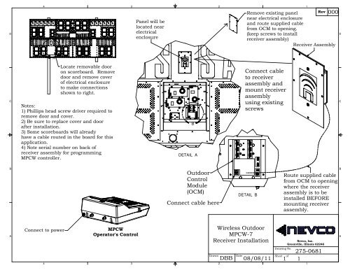
Panel will be<br />
located near<br />
electrical<br />
enclosure<br />
2<br />
1<br />
Rev<br />
000<br />
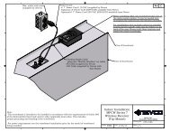
Remove existing panel<br />
near electrical enclosure<br />
and route supplied cable<br />
from OCM to opening.<br />
(keep screws to install<br />
receiver assembly)<br />
Receiver Assembly<br />
D<br />
A<br />
C<br />
Locate removable door<br />
on scoreboard. Remove<br />
door and remove cover<br />
of electrical enclosure<br />
to make connections<br />
shown to right.<br />
Notes:<br />
1) Phillips head screw driver required to<br />
remove door and cover.<br />
2) Be sure to replace cover and door<br />
after installation.<br />
3) Some scoreboards will already<br />
have a cable routed in the board for this<br />
application.<br />
4) Note serial number on back of<br />
receiver assembly for programming<br />
MPCW controller.<br />
B<br />
DETAIL A<br />
Connect cable<br />
to receiver<br />
assembly and<br />
mount receiver<br />
assembly<br />
using existing<br />
screws<br />
C<br />
B<br />
Outdoor<br />
Control<br />
Module<br />
(OCM)<br />
Connect cable here<br />
DETAIL B<br />
Route supplied cable<br />
from OCM to opening<br />
where the receiver<br />
assembly is to be<br />
installed BEFORE<br />
mounting receiver<br />
assembly.<br />
B<br />
A<br />
Connect to power<br />
4<br />
MPCW<br />
Operator's Control<br />
3<br />
Wireless Outdoor<br />
MPCW-7<br />
Receiver <strong>Installation</strong><br />
Drawn<br />
2<br />
DBB<br />
Date<br />
08/08/11<br />
Drawing No.<br />
Sheet of<br />
<strong>Nevco</strong>, Inc.<br />
Greenville, Illinois 62246<br />
275-0681<br />
1 1<br />
1<br />
A
4<br />
3<br />
2<br />
1<br />
Rev<br />
B<br />
D<br />
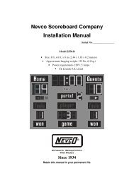
Box, outlet and cover<br />
(supplied by others)<br />
Power Cord:<br />
-6' 7" Power Cord 110 VAC (supplied by <strong>Nevco</strong>)<br />
-Optional 15' Power Cord (009-0324) available from <strong>Nevco</strong><br />
-Optional 6' 7" Power Cord 220 VAC (009-0257) available from <strong>Nevco</strong><br />
D<br />
Coax out to next device.<br />
(See scoreboard installation instructions for information on signal chaining)<br />
C<br />
6 Position Radio Cable (plug into "Module Interface" on radio)<br />
-2ft Cable (supplied by <strong>Nevco</strong>)<br />
-Optional 5ft Cable (009-0323) available from <strong>Nevco</strong><br />
-Optional 14ft Cable (009-0325) available from <strong>Nevco</strong><br />
Top of Scoreboard<br />
C<br />
Face of Scoreboard<br />
B<br />
B<br />
Before installing radio onto scoreboard take note of<br />
the radios serial number. It may be needed later<br />
to program the radio ID into the wireless controller.<br />
For installations with multiple radios the intended<br />
location for the specific radio may be written on the<br />
back of the case. Please verify these locations and<br />
install the radios accordingly.<br />
A<br />
Note:<br />
-This scoreboard is intended to be installed in accordance with the requirements of Article 600<br />
of the National Electrical Code and/or other applicable local codes. This includes<br />
proper grounding and bonding of the scoreboard.<br />
-For power requirements see the scoreboard installation print for the model of scoreboard<br />
being installed<br />
Drawn<br />
Indoor <strong>Installation</strong><br />
MPCW Series 7<br />
Wireless Receiver<br />
(Top Mount)<br />
Date<br />
MMK 8/8/11<br />
Drawing No.<br />
Sheet of<br />
<strong>Nevco</strong>, Inc.<br />
Greenville, Illinois 62246<br />
1 1<br />
275-0166<br />
A<br />
4<br />
3<br />
2<br />
1
4<br />
3<br />
2<br />
1<br />
Rev<br />
B<br />
D<br />
Single gang box with top knockout removed from back.<br />
Box is held in place using conduit elbow connector.<br />
1<br />
Conduit for Coax<br />
to Scoreboard<br />
1<br />
D<br />
9 Volt DC Power Supply<br />
C<br />
Spare Coax Output Jack<br />
C<br />
Attach Receiver to door of<br />
enclosure using two included<br />
adhesive backed fasteners<br />
2<br />
DC Power Jack<br />
Status LED<br />
Twist-on BNC for Coax to Scoreboard<br />
Power Conduit<br />
1<br />
B<br />
B<br />
Included Coax Cable to Scoreboard<br />
System Key Connector (On end of Receiver)<br />
1<br />
2<br />
Notes:<br />
Use Raintight fittings<br />
Mount Receiver box on the<br />
front of the scoreboard post<br />
in clear line of sight from the<br />
control point.<br />
A<br />
4<br />
3<br />
Drawn<br />
2<br />
MPCW-6<br />
Receiver<br />
Raintight Box<br />
<strong>Installation</strong><br />
MMK<br />
Date<br />
9/14/11<br />
Drawing No.<br />
1<br />
Sheet of<br />
<strong>Nevco</strong>, Inc.<br />
Greenville, Illinois 62246<br />
275-0132<br />
1<br />
1<br />
A