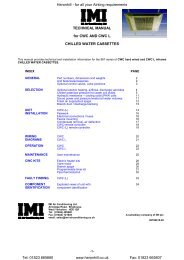
TECHNICAL MANUAL for CWC CHILLED WATER CASSETTE.
TECHNICAL MANUAL for CWC CHILLED WATER CASSETTE.
TECHNICAL MANUAL for CWC CHILLED WATER CASSETTE.

Create successful ePaper yourself
Turn your PDF publications into a flip-book with our unique Google optimized e-Paper software.
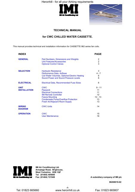
Heronhill - <strong>for</strong> all your Airking requirements<br />
<strong>TECHNICAL</strong> <strong>MANUAL</strong><br />
<strong>for</strong> <strong>CWC</strong> <strong>CHILLED</strong> <strong>WATER</strong> <strong>CASSETTE</strong>.<br />
This manual provides technical and installation in<strong>for</strong>mation <strong>for</strong> <strong>CASSETTE</strong> 962 series fan coils.<br />
INDEX<br />
PAGE<br />
GENERAL Part Numbers, Dimensions and Weights 2<br />
Unit Features/Accessories 2<br />
Optional Control Valves 3<br />
SELECTION Hydraulic Resistance 3<br />
Per<strong>for</strong>mance Data, Airflows 4 - 7<br />
Coil Water Volumes, Optional Electric Heating 8<br />
Sound Power and Sound Pressure Levels 8<br />
ELECTRICAL Electrical Data, Recommended Fuse Sizes 8<br />
UNIT <strong>CWC</strong> 9 - 11<br />
INSTALLATION Pipework 11<br />
Electrical Connections 11<br />
IMI Remote Controller 12<br />
Fascia Mounting 12 - 13<br />
Condensate Pump/Overflow Protection 13<br />
Fresh Air/Adjacent Room Supply 13<br />
WIRING <strong>CWC</strong> Units 14<br />
DIAGRAM<br />
OPERATION <strong>CWC</strong> 15<br />
User Maintenance 16<br />
IMI Air Conditioning Ltd.<br />
Armytage Road, Brighouse,<br />
West Yorkshire. HD6 1QF<br />
Tel: (01484) 405600<br />
Fax: (01484) 721949<br />
A subsidiary company of IMI plc<br />
96208019-02<br />
-1-<br />
Tel: 01823 665660 www.heronhill.co.uk Fax: 01823 665807
Heronhill - <strong>for</strong> all your Airking requirements<br />
IMI AIR CONDITIONING LIMITED-<strong>CASSETTE</strong> CEILING MOUNTED <strong>CHILLED</strong><br />
<strong>WATER</strong> UNITS<br />
PART NUMBERS<br />
<strong>CASSETTE</strong> <strong>CWC</strong> UNITS<br />
Models 8 9 13 19<br />
Part Number (without condensate pump) 96200001 96200002 96200004 96200005<br />
Part Number (with condensate pump) 96200051 96200052 96200054 96200055<br />
UNPACKED DIMENSIONS AND WEIGHTS<br />
<strong>CWC</strong> UNITS<br />
Model<br />
<strong>CWC</strong><br />
8 9 13 19<br />
HEIGHT mm 338 338 338 338<br />
WIDTH mm 647 747 947 1247<br />
DEPTH mm 647 647 647 647<br />
WEIGHT kg 24 31 39 48<br />
PACKED DIMENSIONS AND WEIGHTS<br />
<strong>CWC</strong> UNITS<br />
Model<br />
<strong>CWC</strong><br />
8 9 13 19<br />
HEIGHT mm 510 510 510 510<br />
WIDTH mm 680 780 980 1280<br />
DEPTH mm 710 710 710 710<br />
WEIGHT kg 34 43 52 63<br />
FEATURES/ACCESSORIES<br />
<strong>CWC</strong> UNITS<br />
<strong>CWC</strong><br />
Manually adjustable air deflectors<br />
Automatically adjusted air deflectors *<br />
Electric/LPHW heating *<br />
Electromechanical remote thermostat *<br />
STD<br />
3 fan speeds STD<br />
Branch duct and fresh air inlet *<br />
Programmable timer *<br />
Condensate pump *<br />
Long life washable filter<br />
2 or 3 way valve arrangements *<br />
STD<br />
3 way discharge STD<br />
Key: * = factory/site option. STD = standard.<br />
-2-<br />
Tel: 01823 665660 www.heronhill.co.uk Fax: 01823 665807
Heronhill - <strong>for</strong> all your Airking requirements<br />
OPTIONAL CONTROL VALVES<br />
The choice of either 2 or 3 way valves are available, these are factory fitted and sited within the valve tray to give the<br />
following water flow arrangements.<br />
HYDRAULIC RESISTANCE<br />
-3-<br />
Tel: 01823 665660 www.heronhill.co.uk Fax: 01823 665807
Heronhill - <strong>for</strong> all your Airking requirements<br />
Tel: 01823 665660 www.heronhill.co.uk Fax: 01823 665807<br />
<strong>CWC</strong> 8 COOLING DUTIES<br />
Minimum Speed Medium Speed Maximum Speed<br />
Room Air On CW Temperature 0.077 m 3 /s 0.104 m 3 /s 0.134 m 3 /s<br />
db C wb C IN C OUT C Total Sensible Total Sensible Total Sensible<br />
27 19 6 11 1.79 1.26 2.20 1.59 2.57 1.91<br />
21 15 5 9 1.20 0.95 1.48 1.20 1.73 1.45<br />
21 15 5 11 0.84 0.79 0.96 0.96 1.16 1.16<br />
21 15 5 13 0.71 0.71 0.85 0.85 0.97 0.97<br />
21 15 7 11 0.85 0.79 1.05 1.01 1.23 1.23<br />
21 15 7 13 0.67 0.67 0.80 0.80 0.92 0.92<br />
21 15 7 15 0.58 0.58 0.69 0.69 0.79 0.79<br />
21 15 9 13 0.62 0.62 0.81 0.81 0.99 0.99<br />
21 15 9 15 0.53 0.53 0.64 0.64 0.73 0.73<br />
21 15 9 17 0.45 0.45 0.53 0.53 0.61 0.61<br />
24 17 5 9 1.65 1.18 2.03 1.49 2.38 1.79<br />
24 17 5 11 1.25 1.01 1.57 1.29 1.84 1.56<br />
24 17 5 13 0.97 0.89 1.09 1.09 1.25 1.25<br />
24 17 7 11 1.32 1.03 1.61 1.31 1.89 1.58<br />
24 17 7 13 0.89 0.86 1.08 1.08 1.33 1.33<br />
24 17 7 15 0.78 0.78 0.93 0.93 1.06 1.06<br />
24 17 9 13 0.96 0.88 1.17 1.12 1.36 1.36<br />
24 17 9 15 0.73 0.73 0.88 0.88 1.08 1.08<br />
24 17 9 17 0.65 0.65 0.77 0.77 0.88 0.88<br />
27 19 5 9 2.12 1.41 2.60 1.77 3.05 2.12<br />
27 19 5 11 1.77 1.26 2.18 1.58 2.56 1.91<br />
27 19 5 13 1.29 1.05 1.63 1.36 1.95 1.66<br />
27 19 7 11 1.79 1.26 2.19 1.59 2.56 1.91<br />
27 19 7 13 1.42 1.11 1.75 1.40 2.04 1.70<br />
27 19 7 15 1.03 0.95 1.16 1.16 1.40 1.40<br />
27 19 9 13 1.44 1.11 1.76 1.41 2.05 1.70<br />
27 19 9 15 0.99 0.94 1.26 1.21 1.48 1.48<br />
27 19 9 17 0.84 0.84 1.01 1.01 1.16 1.16<br />
29 19 5 9 2.14 1.57 2.63 1.98 3.08 2.36<br />
29 19 5 11 1.81 1.42 2.22 1.80 2.59 2.17<br />
29 19 5 13 1.31 1.22 1.69 1.58 2.00 1.93<br />
29 19 7 11 1.82 1.43 2.22 1.80 2.59 2.17<br />
29 19 7 13 1.46 1.27 1.78 1.62 2.08 1.96<br />
29 19 7 15 1.10 1.10 1.36 1.36 1.69 1.69<br />
29 19 9 13 1.47 1.28 1.79 1.62 2.08 1.96<br />
29 19 9 15 1.12 1.12 1.43 1.43 1.73 1.73<br />
29 19 9 17 0.97 0.97 1.16 1.16 1.45 1.45<br />
<strong>CWC</strong> 8 HEATING DUTIES<br />
Minimum Speed Medium Speed Maximum Speed<br />
Room Air On LPHW Temperature 0.077 m 3 /s 0.104 m 3 /s 0.134 m 3 /s<br />
db C wb C/%RH IN C OUT C Total Total Total<br />
20 12 80 70 4.15 5.26 6.37<br />
10 50% 90 80 5.83 7.39 8.94<br />
10 50% 90 75 5.59 7.07 8.54<br />
10 50% 80 70 5.03 6.37 7.71<br />
10 50% 80 65 4.79 6.05 7.30<br />
10 50% 65 55 3.84 4.85 5.85<br />
10 50% 65 50 3.58 4.51 5.44<br />
15 50% 90 80 5.37 6.81 8.25<br />
15 50% 90 75 5.14 6.50 7.86<br />
15 50% 80 70 4.58 5.81 7.03<br />
15 50% 80 65 4.34 5.49 6.63<br />
15 50% 65 55 3.40 4.30 5.20<br />
15 50% 65 50 3.15 3.97 4.79<br />
20 50% 90 80 4.92 6.24 7.57<br />
20 50% 90 75 4.69 5.94 7.18<br />
20 50% 80 70 4.14 5.25 6.36<br />
20 50% 80 65 3.91 4.94 5.97<br />
20 50% 65 55 2.98 3.76 4.55<br />
20 50% 65 50 2.72 3.44 4.15<br />
25 50% 90 80 4.48 5.69 6.90<br />
25 50% 90 75 4.25 5.38 6.52<br />
25 50% 80 70 3.71 4.71 5.71<br />
25 50% 80 65 3.48 4.40 5.32<br />
25 50% 65 55 2.56 3.24 3.92<br />
25 50% 65 50 2.30 2.91 3.52<br />
-4-
Heronhill - <strong>for</strong> all your Airking requirements<br />
Tel: 01823 665660 www.heronhill.co.uk Fax: 01823 665807<br />
<strong>CWC</strong> 9 COOLING DUTIES<br />
Minimum Speed Medium Speed Maximum Speed<br />
Room Air On CW Temperature 0.098 m 3 /s 0.122 m 3 /s 0.165 m 3 /s<br />
db C wb C IN C OUT C Total Sensible Total Sensible Total Sensible<br />
27 19 6 11 2.39 1.65 2.77 1.95 3.36 2.44<br />
21 15 5 9 1.62 1.25 1.89 1.48 2.29 1.86<br />
21 15 5 11 1.10 1.02 1.35 1.24 1.67 1.58<br />
21 15 5 13 0.90 0.90 1.03 1.03 1.21 1.21<br />
21 15 7 11 1.19 1.06 1.39 1.26 1.68 1.59<br />
21 15 7 13 0.85 0.85 0.96 0.96 1.27 1.27<br />
21 15 7 15 0.74 0.74 0.84 0.84 0.98 0.98<br />
21 15 9 13 0.85 0.85 1.02 1.02 1.29 1.29<br />
21 15 9 15 0.68 0.68 0.77 0.77 0.91 0.91<br />
21 15 9 17 0.57 0.57 0.65 0.65 0.76 0.76<br />
24 17 5 9 2.18 1.54 2.54 1.83 3.08 2.28<br />
24 17 5 11 1.79 1.36 2.08 1.62 2.53 2.03<br />
24 17 5 13 1.23 1.13 1.34 1.31 1.80 1.73<br />
24 17 7 11 1.76 1.35 2.05 1.60 2.48 2.01<br />
24 17 7 13 1.32 1.16 1.54 1.39 1.87 1.76<br />
24 17 7 15 0.99 0.99 1.12 1.12 1.39 1.39<br />
24 17 9 13 1.32 1.16 1.53 1.38 1.83 1.74<br />
24 17 9 15 0.93 0.93 1.14 1.14 1.46 1.46<br />
24 17 9 17 0.82 0.82 0.93 0.93 1.10 1.10<br />
27 19 5 9 2.77 1.83 3.22 2.16 3.91 2.68<br />
27 19 5 11 2.40 1.66 2.80 1.97 3.39 2.45<br />
27 19 5 13 1.95 1.47 2.29 1.75 2.78 2.20<br />
27 19 7 11 2.35 1.64 2.74 1.94 3.30 2.41<br />
27 19 7 13 1.97 1.47 2.28 1.75 2.76 2.19<br />
27 19 7 15 1.40 1.25 1.70 1.51 2.08 1.93<br />
27 19 9 13 1.92 1.45 2.22 1.72 2.67 2.15<br />
27 19 9 15 1.49 1.28 1.73 1.53 2.08 1.92<br />
27 19 9 17 1.07 1.07 1.22 1.22 1.62 1.62<br />
29 19 5 9 2.80 2.04 3.25 2.41 3.94 3.00<br />
29 19 5 11 2.44 1.87 2.84 2.22 3.43 2.78<br />
29 19 5 13 2.00 1.68 2.34 2.01 2.83 2.53<br />
29 19 7 11 2.39 1.85 2.77 2.19 3.33 2.74<br />
29 19 7 13 2.01 1.68 2.33 2.00 2.80 2.51<br />
29 19 7 15 1.49 1.47 1.77 1.77 2.25 2.25<br />
29 19 9 13 1.95 1.66 2.26 1.97 2.71 2.48<br />
29 19 9 15 1.54 1.49 1.78 1.78 2.24 2.24<br />
29 19 9 17 1.25 1.25 1.53 1.53 1.95 1.95<br />
<strong>CWC</strong> 9 HEATING DUTIES<br />
Minimum Speed Medium Speed Maximum Speed<br />
Room Air On LPHW Temperature 0.098 m 3 /s 0.122 m 3 /s 0.165 m 3 /s<br />
db C wb C/%RH IN C OUT C Total Total Total<br />
20 12 80 70 5.31 6.32 7.96<br />
10 50% 90 80 7.45 8.86 11.14<br />
10 50% 90 75 7.16 8.50 10.68<br />
10 50% 80 70 6.43 7.65 9.62<br />
10 50% 80 65 6.14 7.29 9.15<br />
10 50% 65 55 4.91 5.83 7.33<br />
10 50% 65 50 4.61 5.46 6.84<br />
15 50% 90 80 6.86 8.17 10.28<br />
15 50% 90 75 6.58 7.82 9.83<br />
15 50% 80 70 5.86 6.97 8.78<br />
15 50% 80 65 5.57 6.62 8.31<br />
15 50% 65 55 4.36 5.18 6.51<br />
15 50% 65 50 4.06 4.81 6.03<br />
20 50% 90 80 6.29 7.49 9.44<br />
20 50% 90 75 6.01 7.14 8.99<br />
20 50% 80 70 5.30 6.31 7.95<br />
20 50% 80 65 5.01 5.96 7.49<br />
20 50% 65 55 3.82 4.54 5.70<br />
20 50% 65 50 3.52 4.18 5.23<br />
25 50% 90 80 5.72 6.82 8.61<br />
25 50% 90 75 5.45 6.48 8.16<br />
25 50% 80 70 4.75 5.66 7.13<br />
25 50% 80 65 4.47 5.31 6.68<br />
25 50% 65 55 3.29 3.91 4.92<br />
25 50% 65 50 2.98 3.55 4.45<br />
-5-
Heronhill - <strong>for</strong> all your Airking requirements<br />
Tel: 01823 665660 www.heronhill.co.uk Fax: 01823 665807<br />
<strong>CWC</strong> 13 COOLING DUTIES<br />
Minimum Speed Medium Speed Maximum Speed<br />
Room Air On CW Temperature 0.120 m 3 /s 0.179 m 3 /s 0.243 m 3 /s<br />
db C wb C IN C OUT C Total Sensible Total Sensible Total Sensible<br />
27 19 6 11 2.99 2.06 3.96 2.82 4.81 3.53<br />
21 15 5 9 2.01 1.55 2.68 2.13 3.27 2.68<br />
21 15 5 11 1.32 1.24 1.66 1.66 2.21 2.21<br />
21 15 5 13 1.12 1.12 1.41 1.41 1.65 1.65<br />
21 15 7 11 1.44 1.30 1.94 1.80 2.35 2.28<br />
21 15 7 13 1.05 1.05 1.33 1.33 1.71 1.71<br />
21 15 7 15 0.92 0.92 1.15 1.15 1.34 1.34<br />
21 15 9 13 1.00 1.00 1.45 1.45 1.84 1.84<br />
21 15 9 15 0.84 0.84 1.06 1.06 1.24 1.24<br />
21 15 9 17 0.71 0.71 0.88 0.88 1.02 1.02<br />
24 17 5 9 2.74 1.93 3.64 2.63 4.42 3.30<br />
24 17 5 11 2.14 1.66 2.90 2.30 3.54 2.91<br />
24 17 5 13 1.53 1.40 1.81 1.81 2.32 2.32<br />
24 17 7 11 2.20 1.69 2.92 2.31 3.54 2.91<br />
24 17 7 13 1.40 1.35 2.06 1.95 2.54 2.50<br />
24 17 7 15 1.22 1.22 1.54 1.54 1.81 1.81<br />
24 17 9 13 1.62 1.44 2.15 1.99 2.59 2.52<br />
24 17 9 15 1.15 1.15 1.55 1.55 2.05 2.05<br />
24 17 9 17 1.02 1.02 1.28 1.28 1.49 1.49<br />
27 19 5 9 3.50 2.30 4.64 3.12 5.63 3.00<br />
27 19 5 11 2.98 2.06 3.97 2.82 4.83 3.54<br />
27 19 5 13 2.03 1.66 3.11 2.46 3.82 3.12<br />
27 19 7 11 2.97 2.06 3.93 2.80 4.75 3.50<br />
27 19 7 13 2.41 1.82 3.21 2.50 3.89 3.15<br />
27 19 7 15 1.63 1.50 2.00 2.00 2.69 2.69<br />
27 19 9 13 2.41 1.82 3.18 2.49 3.82 3.12<br />
27 19 9 15 1.74 1.55 2.37 2.17 2.87 2.75<br />
27 19 9 17 1.32 1.32 1.68 1.68 2.21 2.21<br />
29 19 5 9 3.53 2.56 4.68 3.49 5.67 4.35<br />
29 19 5 11 3.03 2.33 4.03 3.19 4.89 4.01<br />
29 19 5 13 2.26 1.99 3.19 2.84 3.91 3.60<br />
29 19 7 11 3.01 2.32 3.98 3.17 4.79 3.97<br />
29 19 7 13 2.47 2.08 3.28 2.87 3.96 3.62<br />
29 19 7 15 1.74 1.74 2.48 2.48 3.18 3.18<br />
29 19 9 13 2.46 2.08 3.23 2.85 3.88 3.59<br />
29 19 9 15 1.83 1.82 2.54 2.54 3.22 3.22<br />
29 19 9 17 1.53 1.53 2.10 2.10 2.74 2.74<br />
<strong>CWC</strong> 13 HEATING DUTIES<br />
Minimum Speed Medium Speed Maximum Speed<br />
Room Air On LPHW Temperature 0.120 m 3 /s 0.179 m 3 /s 0.243 m 3 /s<br />
db C wb C/%RH IN C OUT C Total Total Total<br />
20 12 80 70 6.67 9.18 11.58<br />
10 50% 90 80 9.36 12.88 16.22<br />
10 50% 90 75 9.00 12.35 15.54<br />
10 50% 80 70 8.09 11.12 14.00<br />
10 50% 80 65 7.72 10.58 13.30<br />
10 50% 65 55 6.18 8.47 10.65<br />
10 50% 65 50 5.79 7.92 9.94<br />
15 50% 90 80 8.62 11.87 14.97<br />
15 50% 90 75 8.26 11.35 14.30<br />
15 50% 80 70 7.37 10.13 12.77<br />
15 50% 80 65 7.00 9.61 12.08<br />
15 50% 65 55 5.48 7.52 9.46<br />
15 50% 65 50 5.09 6.98 8.76<br />
20 50% 90 80 7.09 10.89 13.74<br />
20 50% 90 75 7.54 10.38 13.08<br />
20 50% 80 70 6.66 9.17 11.57<br />
20 50% 80 65 6.30 8.65 10.89<br />
20 50% 65 55 4.80 6.59 8.29<br />
20 50% 65 50 4.41 6.05 7.60<br />
25 50% 90 80 7.18 9.92 12.53<br />
25 50% 90 75 6.84 9.42 11.87<br />
25 50% 80 70 5.96 8.22 10.38<br />
25 50% 80 65 5.61 7.71 9.71<br />
25 50% 65 55 4.13 5.67 7.15<br />
25 50% 65 50 3.73 5.13 6.4<br />
-6-
Heronhill - <strong>for</strong> all your Airking requirements<br />
Tel: 01823 665660 www.heronhill.co.uk Fax: 01823 665807<br />
<strong>CWC</strong> 19 COOLING DUTIES<br />
Minimum Speed Medium Speed Maximum Speed<br />
Room Air On CW Temperature 0.129 m 3 /s 0.179 m 3 /s 0.243 m 3 /s<br />
db C wb C IN C OUT C Total Sensible Total Sensible Total Sensible<br />
27 19 6 11 3.46 2.36 4.47 3.08 5.56 3.91<br />
21 15 5 9 2.32 1.77 3.02 2.32 3.77 2.96<br />
21 15 5 11 1.59 1.43 1.83 1.79 2.30 2.30<br />
21 15 5 13 1.31 1.31 1.60 1.60 1.89 1.89<br />
21 15 7 11 1.64 1.45 2.19 1.95 2.74 2.50<br />
21 15 7 13 1.22 1.22 1.50 1.50 1.79 1.79<br />
21 15 7 15 1.07 1.07 1.30 1.30 1.54 1.54<br />
21 15 9 13 1.14 1.14 1.53 1.53 2.01 2.01<br />
21 15 9 15 0.98 0.98 1.20 1.20 1.42 1.42<br />
21 15 9 17 0.83 0.83 1.00 1.00 1.18 1.18<br />
24 17 5 9 3.17 2.21 4.09 2.88 5.10 3.66<br />
24 17 5 11 2.37 1.84 3.24 2.50 4.10 3.21<br />
24 17 5 13 1.85 1.61 2.11 2.02 2.44 2.44<br />
24 17 7 11 2.56 1.92 3.30 2.52 4.11 3.21<br />
24 17 7 13 1.69 1.55 1.95 1.95 2.94 2.72<br />
24 17 7 15 1.42 1.42 1.74 1.74 2.07 2.07<br />
24 17 9 13 1.88 1.63 2.45 2.16 3.04 2.76<br />
24 17 9 15 1.34 1.34 1.65 1.65 2.15 2.15<br />
24 17 9 17 1.18 1.18 1.45 1.45 1.71 1.71<br />
27 19 5 9 4.05 2.63 5.21 3.42 6.48 4.32<br />
27 19 5 11 3.45 2.35 4.48 3.09 5.59 3.92<br />
27 19 5 13 2.44 1.92 3.38 2.61 4.41 3.43<br />
27 19 7 11 3.45 2.35 4.43 3.07 5.50 3.88<br />
27 19 7 13 2.77 2.05 3.63 2.72 4.54 .348<br />
27 19 7 15 1.97 1.73 2.24 2.17 2.77 2.77<br />
27 19 9 13 2.81 2.07 3.61 2.71 4.46 3.45<br />
27 19 9 15 1.81 1.67 2.67 2.33 3.38 3.02<br />
27 19 9 17 1.54 1.54 1.89 1.89 2.25 2.25<br />
29 19 5 9 4.09 2.92 5.27 3.81 6.54 4.83<br />
29 19 5 11 3.51 2.65 4.55 3.48 5.67 4.43<br />
29 19 5 13 2.50 2.21 3.52 3.03 4.54 3.95<br />
29 19 7 11 3.50 2.64 4.49 3.45 5.57 4.39<br />
29 19 7 13 2.85 2.36 3.72 3.11 4.63 3.98<br />
29 19 7 15 2.03 202 2.49 2.49 3.44 3.44<br />
29 19 9 13 2.86 2.36 3.68 3.10 4.54 3.95<br />
29 19 9 15 2.00 2.00 2.78 2.73 3.53 3.53<br />
29 19 9 17 1.78 1.78 2.19 2.19 2.91 2.91<br />
<strong>CWC</strong> 19 HEATING DUTIES<br />
Minimum Speed Medium Speed Maximum Speed<br />
Room Air On LPHW Temperature 0.129 m 3 /s 0.179 m 3 /s 0.243 m 3 /s<br />
db C wb C/%RH IN C OUT C Total Total Total<br />
20 12 80 70 7.53 9.91 12.66<br />
10 50% 90 80 10.57 13.90 17.74<br />
10 50% 90 75 10.19 13.36 17.03<br />
10 50% 80 70 9.15 12.01 15.32<br />
10 50% 80 65 8.75 11.47 14.60<br />
10 50% 65 55 7.00 9.18 11.69<br />
10 50% 65 50 6.58 8.62 10.95<br />
15 50% 90 80 9.73 12.80 16.36<br />
15 50% 90 75 9.35 12.28 15.66<br />
15 50% 80 70 8.32 10.94 13.97<br />
15 50% 80 65 7.93 10.41 13.26<br />
15 50% 65 55 6.20 8.14 10.38<br />
15 50% 65 50 5.78 7.58 9.65<br />
20 50% 90 80 8.90 11.72 15.00<br />
20 50% 90 75 8.53 11.21 14.31<br />
20 50% 80 70 7.51 9.89 12.64<br />
20 50% 80 65 7.13 9.36 11.94<br />
20 50% 65 55 5.43 7.13 9.09<br />
20 50% 65 50 4.99 6.56 8.37<br />
25 50% 90 80 8.09 10.67 13.66<br />
25 50% 90 75 7.72 10.16 12.99<br />
25 50% 80 70 6.73 8.86 11.33<br />
25 50% 80 65 6.35 8.34 10.64<br />
25 50% 65 55 4.67 6.14 7.83<br />
25 50% 65 50 4.22 5.56 7.10<br />
-7-
Heronhill - <strong>for</strong> all your Airking requirements<br />
<strong>WATER</strong> VOLUME IN COILS (litres)<br />
COIL 8 9 13 19<br />
COOLING 1.0 1.2 1.6 2.1<br />
HEATING 0.4 0.5 0.6 0.8<br />
OPTIONAL ELECTRIC HEATING<br />
at 230V 50Hz at 240V 50Hz<br />
<strong>CWC</strong> (kW) (kW)<br />
8 1.4 1.5<br />
9 1.8 2.0<br />
13 2.3 2.5<br />
19 3.4 3.75<br />
SOUND POWER and SOUND PRESSURE LEVELS<br />
962 SERIES <strong>CWC</strong><br />
SOUND POWER LEVELS<br />
Frequency Hz<br />
SOUND PRESSURE<br />
LEVELS<br />
MODEL SPEED 125 250 500 1K 2K 4K dBA dBA NC<br />
8<br />
9<br />
13<br />
19<br />
Min 49.1 51.4 51.2 47.1 41.0 40.7 52.7 31.7 24<br />
Med 50.6 52.7 52.7 48.8 41.6 37.8 53.6 32.6 26<br />
Max 54.3 57.2 54.3 50.9 43.9 40.8 55.8 34.8 28<br />
Min 50.2 52.0 50.9 47.5 41.0 39.5 52.7 31.7 25<br />
Med 52.6 54.1 53.6 50.6 43.1 39.6 55.1 34.1 28<br />
Max 56.2 56.3 55.2 53.1 45.3 40.6 57.0 36.0 30<br />
Min 50.3 51.7 50.4 46.8 43.1 44.4 53.5 32.5 26<br />
Med 54.8 54.8 53.9 50.4 44.6 44.3 55.8 34.8 28<br />
Max 58.5 57.4 55.0 52.4 46.0 44.8 57.2 36.2 30<br />
Min 50.7 52.3 49.7 44.8 35.7 30.8 50.2 29.2 22<br />
Med 55.3 55.6 53.7 49.6 41.2 34.6 54.6 33.6 27<br />
Max 58.3 58.2 55.3 52.3 43.9 38.0 56.8 35.8 30<br />
Sound Power Levels were obtained in full con<strong>for</strong>mity with BS 4196: Part 5: 1981. Quantities are shown in dB with a standard<br />
reference of 1 pW.<br />
Sound Pressure Levels are dB relative to 2 x 10 -5 N/m 2 and are calculated from the results under anechoic conditions and are<br />
quoted as an average of all points on a hemisphere of a radius of 3m away, 1m down from the centre of the unit.<br />
ELECTRICAL DATA<br />
<strong>CWC</strong> Maximum Running Current in Amps (At 230 V, 50 Hz).<br />
Model 8 9 13 19<br />
Standard 0.3 0.3 0.3 0.4<br />
With Electric Htg 6.3 8.3 10.4 15.6<br />
RECOMMENDED FUSE SIZES (Amps)<br />
Model 8 9 13 19<br />
Standard 3 3 3 3<br />
With Electric Htg 10 13 13 20<br />
-8-<br />
Tel: 01823 665660 www.heronhill.co.uk Fax: 01823 665807
Heronhill - <strong>for</strong> all your Airking requirements<br />
962 SERIES <strong>CWC</strong> <strong>CASSETTE</strong> INSTALLATION<br />
The 962 SERIES <strong>CWC</strong> <strong>CASSETTE</strong> is designed to operate within a suspended false ceiling.<br />
The installer supplies:<br />
Unpacking<br />
Remote thermostat (available separately, part number 96000320)<br />
4 lengths of screwed rod (M8, M10 or 3/8" OD) with 12 nuts, to suspend the chassis.<br />
Method of securing screwed rod to solid ceiling e.g. Rawl bolt shields.<br />
All mains wiring, with suitable isolation.<br />
Interconnecting wires <strong>for</strong> remote thermostat, (available from IMI in 100m drums; part number 00526116S).<br />
Insulated pipework.<br />
2 screws to secure the remote thermostat.<br />
Condensate drain (21.5mm OD <strong>for</strong> gravity drain or 8mm ID if a condensate pump is fitted).<br />
Carefully unfasten the box and lift off the cardboard sleeve to gain access to the unit.<br />
The following are supplied:<br />
* Cassette unit complete with fascia * 8 washers - Use on suspension brackets<br />
* 2 Suspension brackets * 4 screws - Chassis to suspension brackets<br />
* Cardboard template <strong>for</strong> marking out rod * 4 pointed screws - Fascia frame to chassis<br />
mounting centres * 2 cable clamps - External cable entries<br />
* Envelope containing operating<br />
instructions <strong>for</strong> the end user<br />
The fascia must be removed, (as shown below), and carefully set aside prior to mounting the chassis.<br />
1 Remove the smaller rear panel and filter by depressing the panel above each rear corner to release the latches.<br />
Hinge the panel upwards and disengage the panel hooks.<br />
2 Remove the fascia panel by undoing the 2 captive screws above the fan deck. Raise the angled edge of the<br />
panel whilst sliding it <strong>for</strong>wards to disengage the locating hooks on the front corners.<br />
3 Remove the fascia frame by depressing the spring latches on the inside of the chassis on opposite corners<br />
to disengage the tabs on the frame. The frame may now be carefully lifted away from the chassis.<br />
Chassis Mounting<br />
NOTE:<br />
It is generally easier to fit kits prior to mounting the unit and connecting the pipework.<br />
Units are sized to allow each chassis to fit conveniently in a standard tiled ceiling although it is recommended that the ceiling<br />
is built with the unit in position; the <strong>CWC</strong> 8 in a 600mm x 600mm tile space and the <strong>CWC</strong> 9 to 13 in a 1200mm x 600mm<br />
tile space.<br />
Units may be fitted into plasterboard ceilings but access traps <strong>for</strong> the condensate pump and pipework must be provided.<br />
Location of the unit will depend on the room shape, load and number of units installed. Typical options are:<br />
-9-<br />
Tel: 01823 665660 www.heronhill.co.uk Fax: 01823 665807
Heronhill - <strong>for</strong> all your Airking requirements<br />
1 Determine the position <strong>for</strong> the unit; the air inlet must be at least 400mm from the nearest wall. Also ensure that the<br />
position does not interfere with light fittings, sprinkler heads, etc..<br />
2 Identify the type of ceiling and ensure that the mounting surface will support the operating weight of the cassette:<br />
MODEL 8 9 13 19<br />
OPERATING WEIGHT (kg) 25.5 32.5 41.0 51.0<br />
3 If fitting the unit after the ceiling has been installed, remove the ceiling tile(s) to accept the chassis, plus adjacent<br />
tiles on each side <strong>for</strong> general access.<br />
* Remove these tiles <strong>for</strong> complete installation access.<br />
4 The chassis should be supported by four screwed rods and 12 nuts (M8, M10 or 3/8"OD) supplied by the installer.<br />
Rod mounting centres are shown at + - + below; use the template provided to mark these out.<br />
Model 8 9 13 19<br />
A (Chassis depth) 568 568 568 568<br />
B (Chassis width) 565 665 865 1165<br />
C (Fascia depth) 647 647 647 647<br />
D (Fascia width) 647 747 947 1247<br />
E (Height above ceiling) 293 293 293 293<br />
F (Rod mounting centres) 494 494 794 794<br />
G (Rod mounting centres) 604 604 604 604<br />
H (Base to suspension hook) 92 92 92 92<br />
-10-<br />
Tel: 01823 665660 www.heronhill.co.uk Fax: 01823 665807
Heronhill - <strong>for</strong> all your Airking requirements<br />
On plasterboard suspended ceilings, remove sufficient of the ceiling to<br />
give clearance <strong>for</strong> the unit to be fitted, and <strong>for</strong> access to pipework and<br />
electrics at the right hand side (motor end); a trap door should be left <strong>for</strong><br />
service access to electrics and pipework.<br />
On rein<strong>for</strong>ced concrete ceilings use Rawl bolt shields or equivalent.<br />
On wooden ceilings use battens <strong>for</strong> a mounting frame.<br />
5 If a heater kit or LPHW coil is to be used, fit prior to mounting the<br />
unit.<br />
6 Hang the four mounting rods; using twelve nuts and eight washers<br />
support the suspension brackets so that the hooks are<br />
approximately 120 - 130mm above the lower surface of the<br />
suspended ceiling<br />
7 Remove the right hand blanking plate (7 screws) from the chassis<br />
to expose the open ends of the coil inlet and outlet pipes; the outlet<br />
pipe is identifiable by the bleed valve.<br />
8 Remove and retain the finger guard (1 screw)<br />
9 Carefully lift the chassis up to the suspension brackets and locate<br />
the hooks on the suspension brackets into the chassis. Use the<br />
nuts to jack the chassis up until the flange is flush with the<br />
suspended ceiling. Ensure that the chassis is level in two<br />
directions, even if the ceiling is not; failure to do so may result<br />
in incorrect condensate drainage or noisy fan operation. Lock<br />
the nuts securely.<br />
10 Secure the chassis to the suspension brackets using the four screws provided, (2 each side).<br />
PIPEWORK<br />
IMPORTANT:<br />
Do NOT use solenoid valves with this unit as they will render the overflow protection switch useless.<br />
If no alternative is available, replace the switch with a length of 1.5 square millimetres diameter wire.<br />
Pipework is terminated at the right hand end of the unit and is 15mm waterpipe.<br />
Pipe runs can be brazed or compression fittings may be used.<br />
When brazing, mask the chassis to prevent burning of the insulation.<br />
It is preferable to fit valves once the unit has been mounted in the ceiling. These are available factory<br />
fitted, with compression fittings, or as a 'field-fit' kit.<br />
ELECTRICAL CONNECTIONS<br />
Refer to page 8 <strong>for</strong> all electrical data.<br />
All mains and control cables must be supplied and fitted by the installer.<br />
The installer wiring must be carried out in accordance with IEE regulations and local codes.<br />
All cables must be size compatible with the recommended fuse <strong>for</strong> a given system.<br />
An isolator switch should be positioned within easy reach of the unit.<br />
The equipment MUST be earthed.<br />
Cable glands suitable <strong>for</strong> stranded cables are supplied and should be used to secure all cables. Installers must supply a<br />
method of securing any solid sheathed cable.<br />
FIRE LINK<br />
In order to automatically switch off the fan in the event of a fire, it is necessary to fit an external switch (240V, 3A, closed<br />
to run, volt free contact) between terminal block terminal 2 and the IMI remote control thermostat (if fitted) terminal 2. This<br />
switch should be operated by the building's fire alarm or BMS system.<br />
-11-<br />
Tel: 01823 665660 www.heronhill.co.uk Fax: 01823 665807
Heronhill - <strong>for</strong> all your Airking requirements<br />
INSTALLATION of the IMI REMOTE CONTROLLER, (if used).<br />
The thermostat should be wired with 7 cores of double insulated 230V cable, 0.5 square millimetres minimum, (available<br />
from IMI in 100m drums; part number 00526116S), preferably in plastic conduit <strong>for</strong> good appearance.<br />
Select a position to mount the thermostat taking into account the following comments:<br />
a<br />
b<br />
c<br />
d<br />
e<br />
f<br />
The thermostat must be mounted on a flat surface within the area conditioned by the <strong>CWC</strong> to which it is<br />
connected.<br />
Avoid draughts, heat from radiators, temperature variations from hot/cold water pipes and direct sunlight.<br />
Avoid corners of the room where air is likely to stagnate.<br />
Avoid direct air discharge from the <strong>CWC</strong> unit.<br />
Avoid positions where the thermostat may be covered or obscured.<br />
If the room contains pillars, mount on the side of the pillar furthest away from the unit. If necessary, consider<br />
blocking off the air discharge from the side facing the thermostat.<br />
Carefully prise off the push-fit dial on the remote control, unscrew the retaining screw and remove the control cover.<br />
Mount the control directly to a wall or onto a plinth, using two suitable fasteners, (not supplied).<br />
Wire between the remote control and the <strong>CWC</strong> unit as shown in the wiring diagram, preferably using multi-core cable,<br />
(wiring diagram on page 14).<br />
Setting instructions:<br />
The cooling differential (cool in to cool out) is fixed at 1.8 +/- 0.5C.<br />
The heating differential (heat in to heat out) is fixed at 1.5 +/- 0.5C.<br />
The deadband is fixed at 1.2 +/- 0.7C.<br />
The set point limits can be adjusted on the back of the push-fit dial; DO NOT SET THE LOWER SET POINT BELOW 15C.<br />
FASCIA MOUNTING<br />
Ensure that the chassis is electrically isolated.<br />
Frame Assembly Mounting<br />
Offer the frame assembly up to the chassis ensuring that the side with no deflector vane is below the fan deck.<br />
Allow the slots in the frame assembly, on each long side, to locate into the spring clips on the chassis.<br />
Secure the frame assembly in situ, from the inside of the chassis, using the four screws provided.<br />
If a vane motor is fitted, connect the three pin plug from the vane motor assembly to the socket adjacent to the fan. Replace<br />
the finger guard.<br />
Fascia Panel Mounting<br />
Locate the large fascia panel by sliding the flange on the top of the panel under the locating hooks on the front corners<br />
(push aside some insulation if<br />
necessary).<br />
Pull the panel fully onto the locating<br />
hooks and simultaneously raise the<br />
rear edge to meet the angle on the<br />
baffle plate.<br />
Secure the panel to the baffle, using<br />
the two captive screws provided,<br />
through the holes in the baffle plate.<br />
Tighten the screws only as far as is<br />
necessary to allow the panel to sit<br />
parallel to the fascia frame.<br />
-12-<br />
Tel: 01823 665660 www.heronhill.co.uk Fax: 01823 665807
Heronhill - <strong>for</strong> all your Airking requirements<br />
Rear Panel Assembly<br />
The vane on this panel is fixed in position and is not adjustable.<br />
1 Fit the filter to the rear panel assembly by dropping the pins at each end of the filter into the slots provided in the rear<br />
panel locating brackets. Ensure that the angled legs of the filter are uppermost. The filter should fit below the tabs in<br />
the rear panel locating brackets.<br />
2 Offer the rear panel up to the unit (filter uppermost) allowing the panel hooks to pass through the slots in the fascia<br />
panel. Pivot the filter upwards at the vane side of the panel, shown below, to allow it to clear the frame. Swing the<br />
panel upwards until the pin latches locate with the rear corners. Ensure that the pin latches are engaged by firmly<br />
pressing the panel upwards immediately below each corner.<br />
NOTE:<br />
Should the pin latches not engage, the location plates in the corner mouldings can be repositioned to<br />
suit by moving the plates, using a screwdriver or similar tool.<br />
The three air off vanes are manually adjusted unless a vane motor kit is fitted when, on units with heating available, the<br />
vanes move automatically to direct warm air downwards.<br />
Condensate Removal<br />
Condensate is collected in a series of drip catchers, running down into a sump. The sump is linked to a connector secured<br />
to the side panel at the motor/pipe end of the unit. A straight adaptor is supplied loose and this can be screwed onto the<br />
outer thread of the connector. The adaptor will accept 22.5mm OD pipe. Check that there is sufficient fall and water drains<br />
freely from the sump without leaking.<br />
An overflow switch is fitted to the drain sump which will prevent further cooling should the gravity drain become blocked.<br />
If a condensate pump is fitted, connect an 8mm bore hose to the white connector pushed through a grommet at the<br />
motor/pipe end of the unit. The use of an 8mm hose should prevent syphoning occurring. But, if the drain outlet is below<br />
the level of the pump and syphoning does occur fit an air break no lower than 200mm below the level of the pump.<br />
The pump is driven by a sensor sited in the drain sump. If the condensate pump fails the condensate level will rise and a<br />
second sensor will break the cooling circuit.<br />
IMPORTANT:<br />
NOTE:<br />
When the unit is first switched on, the sensors will require up to one minute to stabilise be<strong>for</strong>e cooling<br />
is available or the pump will run.<br />
The clear plastic hose fitted to the sump allows the installer to drain the sump prior to removal during<br />
maintenance work. UNDER NO CIRCUMSTANCES SHOULD THIS BE USED AS A GRAVITY<br />
DRAIN.<br />
Fresh Air/Adjacent Room Supply<br />
100mm diameter holes are provided on both the air on and air off<br />
sides of the chassis <strong>for</strong> fresh air/adjacent room supply facilities.<br />
The installer has to provide ducting, external filter and slave fan<br />
if required. As supplied, the holes are blanked with insulation<br />
foam. Typical fresh air intake is approximately 10% at Maximum<br />
speed. The adjacent room supply facility must be used with a<br />
slave fan.<br />
Dimension 8 9 13/19<br />
A 195 195 195<br />
B 95 95 95<br />
C 142 192 431<br />
-13-<br />
Tel: 01823 665660 www.heronhill.co.uk Fax: 01823 665807
Heronhill - <strong>for</strong> all your Airking requirements<br />
<strong>CWC</strong> WIRING DIAGRAM<br />
-14-<br />
Tel: 01823 665660 www.heronhill.co.uk Fax: 01823 665807
Heronhill - <strong>for</strong> all your Airking requirements<br />
<strong>CWC</strong> <strong>CHILLED</strong> <strong>WATER</strong> <strong>CASSETTE</strong> OPERATING INSTRUCTIONS<br />
REMOTE CONTROLLER<br />
Controls to operate the fan speeds and thermostat are on the front face of the controller.<br />
ON/OFF AND FAN SPEEDS<br />
The switches on the left hand side control the ON/OFF and fan speed operations.<br />
The lower left hand switch is the ON/OFF control. The green neon is lit when the switch is 'ON'.<br />
The upper left hand switch operates the fan speeds<br />
The fan speed switch gives:- minimum fan speed at position<br />
medium fan speed at position<br />
maximum fan speed at position<br />
TEMPERATURE CONTROL<br />
The right hand knob selects temperature, which is automatically controlled by the thermostat in the remote control housing;<br />
the range is factory set from 17C to 30C.<br />
By turning anti-clockwise, lower room temperatures are maintained; by turning clockwise, higher room temperatures<br />
are maintained.<br />
The white neon is lit when the unit is in cooling mode.<br />
The amber neon is lit when the unit is in heating mode (if heating is fitted*).<br />
Neither neon is lit when the thermostat is between cooling and heating.<br />
(*Electric heating is available as an optional kit; Low Pressure Hot Water heating is only available as a factory fitted option).<br />
-15-<br />
Tel: 01823 665660 www.heronhill.co.uk Fax: 01823 665807
Heronhill - <strong>for</strong> all your Airking requirements<br />
User Maintenance<br />
WARNING:<br />
The deflector vane on the rear, (air on), panel is fixed in position and does not move.<br />
DO NOT ATTEMPT TO ADJUST ITS POSITION<br />
Isolate at the mains be<strong>for</strong>e commencing any maintenance work.<br />
In order to maintain maximum efficiency it is important that the filter behind the return grille is cleaned regularly; this will<br />
normally be every two to three weeks.<br />
To remove the filter, push the rear panel upwards at each corner to release the latches, and gently lower by hand, (see<br />
below).<br />
DO NOT ALLOW TO SWING FREELY.<br />
The rear panel may be removed from the unit by tilting it to approximately 45 from the horizontal and carefully lifting to<br />
disengage the location hooks; the panel will now slide clear of the fascia.<br />
The filter may be lifted from its slots and cleaned by vacuuming, tapping gently or washing.<br />
THE UNIT SHOULD ALWAYS BE USED WITH A FILTER. FAILURE TO DO SO WILL CAUSE A DECLINE<br />
IN UNIT PERFORMANCE AND MAY RESULT IN MALFUNCTION.<br />
We recommend that in order to prolong the life and maintain per<strong>for</strong>mance of your 'Airking' units you arrange a regular<br />
service contract with your IMI Air Conditioning Ltd. installer/dealer.<br />
-16-<br />
Tel: 01823 665660 www.heronhill.co.uk Fax: 01823 665807