Vectra® - Hi Polymers
Vectra® - Hi Polymers
Vectra® - Hi Polymers

You also want an ePaper? Increase the reach of your titles
YUMPU automatically turns print PDFs into web optimized ePapers that Google loves.
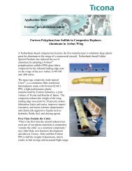
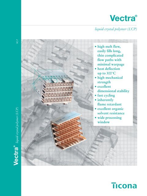
Vectra ®<br />
liquid crystal polymer (LCP)<br />
Vectra ® liquid crystal polymer (LCP) VC-7<br />
• high melt flow,<br />
easily fills long,<br />
thin complicated<br />
flow paths with<br />
minimal warpage<br />
• heat deflection<br />
up to 300°C<br />
• high mechanical<br />
strength<br />
• excellent<br />
dimensional stability<br />
• fast cycling<br />
• inherently<br />
flame retardant<br />
• excellent organic<br />
solvent resistance<br />
• wide processing<br />
window
Vectra ®<br />
liquid crystal polymer (LCP)<br />
Table of Contents<br />
1. Introduction and Overview<br />
2. Vectra ® LCP Product Line<br />
2.1 Grade Description<br />
2.1.1 Glass fiber reinforced grades (100-series)<br />
2.1.2 Carbon fiber reinforced grades (200-series)<br />
2.1.3 Filler/fiber combinations (400-series)<br />
2.1.4 Mineral filled grades (500-series)<br />
2.1.5 Graphite filled grades (600-series)<br />
2.1.6 Specialty grades (700 and 800-series)<br />
2.2 Colors<br />
2.3 Packaging<br />
3. Physical Properties<br />
3.1 Mechanical properties<br />
3.1.1 Effect of anisotropy and wall thickness<br />
3.1.2 Short term stress<br />
3.1.3 Behavior under long term stress<br />
3.1.4 Notch sensitivity (Impact testing)<br />
3.1.5 Fatigue<br />
3.1.6 Tribological properties<br />
3.1.7 Damping<br />
3.2 Thermal properties<br />
3.2.1 Dynamic mechanical spectra<br />
3.2.2 Deflection temperature under load<br />
3.2.3 Coefficient of linear thermal expansion<br />
3.2.4 Soldering compatibility<br />
3.2.5 Thermodynamics, phase transition<br />
3.3 Flammability and combustion<br />
3.4 Electrical properties<br />
3.5 Regulatory Approvals<br />
3.5.1 Food and Drug Administration<br />
3.5.2 United States Pharmacopoeia<br />
3.5.3 Biological Evaluation of Medical Devices<br />
(ISO 10993)<br />
3.5.4 Underwriters Laboratories<br />
3.5.5 Canadian Standards Association<br />
3.5.6 Water Approvals – Germany and Great Britain<br />
4. Environmental Effects<br />
4.1 Hydrolysis<br />
4.2 Chemicals and solvents<br />
4.3 Permeability<br />
4.4 Radiation resistance<br />
4.5 Ultraviolet and weathering resistance<br />
9<br />
12<br />
12<br />
12<br />
12<br />
12<br />
12<br />
12<br />
12<br />
14<br />
14<br />
15<br />
16<br />
16<br />
18<br />
19<br />
20<br />
20<br />
21<br />
21<br />
22<br />
22<br />
24<br />
24<br />
26<br />
26<br />
28<br />
29<br />
33<br />
33<br />
33<br />
33<br />
33<br />
33<br />
33<br />
34<br />
34<br />
35<br />
37<br />
37<br />
37<br />
2
Vectra ®<br />
liquid crystal polymer (LCP)<br />
5. Processing<br />
39<br />
Introduction<br />
and Overview<br />
1<br />
5.1 Safety considerations<br />
5.1.1 Start up and shutdown procedures<br />
5.1.2 Fire precautions<br />
5.2 Drying<br />
39<br />
39<br />
40<br />
40<br />
Vectra LCP<br />
Product Line<br />
2<br />
6. Injection Molding<br />
6.1 Equipment selection<br />
6.1.1 General<br />
6.1.2 Screw design<br />
6.1.3 Check ring<br />
6.1.4 Nozzle<br />
6.1.5 Hot runner systems<br />
6.2 Injection molding processing conditions<br />
6.2.1 Melt temperature<br />
6.2.2 Injection velocity<br />
6.2.3 Mold temperature<br />
6.2.4 Screw speed<br />
6.2.5 Backpressure<br />
6.2.6 Screw decompression<br />
6.2.7 Injection pressure<br />
6.2.8 Holding pressure<br />
6.2.9 Cycle time<br />
6.3 Regrind<br />
6.3.1 General recommendations<br />
6.3.2 Equipment<br />
6.3.3 Using regrind<br />
6.4 Troubleshooting<br />
6.4.1 Brittleness<br />
6.4.2 Burn marks<br />
6.4.3 Dimensional variability<br />
6.4.4 Discoloration<br />
6.4.5 Flashing<br />
6.4.6 Jetting<br />
6.4.7 Leaking check ring<br />
6.4.8 Nozzle problems<br />
6.4.9 Short shots<br />
6.4.10 Sinks and voids<br />
6.4.11 Sticking<br />
6.4.12 Surface marks and blisters<br />
6.4.13 Warpage and part distortion<br />
6.4.14 Weld lines<br />
7. Extrusion<br />
41<br />
41<br />
41<br />
41<br />
41<br />
42<br />
42<br />
43<br />
43<br />
43<br />
43<br />
43<br />
43<br />
43<br />
44<br />
44<br />
44<br />
44<br />
44<br />
45<br />
45<br />
45<br />
45<br />
46<br />
46<br />
46<br />
46<br />
46<br />
46<br />
46<br />
46<br />
46<br />
47<br />
47<br />
47<br />
47<br />
48<br />
Physical<br />
Properties<br />
Environmental<br />
Effects<br />
Processing<br />
Injection<br />
Molding<br />
Extrusion<br />
Rheology<br />
Design<br />
Secondary<br />
Operations<br />
Conversion<br />
Tables<br />
3<br />
4<br />
5<br />
6<br />
7<br />
8<br />
9<br />
10<br />
11<br />
7.1 Equipment selection<br />
7.1.1 General<br />
7.1.2 Screw design<br />
48<br />
48<br />
48<br />
Index<br />
12<br />
3
Vectra ®<br />
liquid crystal polymer (LCP)<br />
7.1.3 Screen pack<br />
7.1.4 Head and die<br />
7.1.5 Melt pump<br />
7.2 Processing<br />
7.2.1 Film and sheet<br />
7.2.2 Profiles<br />
7.2.3 Pipe and tubing<br />
7.2.4 Overcoating<br />
7.3 Troubleshooting<br />
7.3.1 General extrusion<br />
7.3.2 Pipe and tubing<br />
7.3.3 Profiles<br />
7.3.4 Film and sheet<br />
7.3.5 Overcoating<br />
8. Rheology<br />
9. Design<br />
9.1 Part design<br />
9.1.1 Nominal wall thickness<br />
9.1.2 Flow length and wall thickness<br />
9.1.3 Shrinkage<br />
9.1.4 Draft angle<br />
9.1.5 Warpage<br />
9.1.6 Weld lines<br />
9.1.7 Ribs, corners, radii<br />
9.1.8 Holes and depressions<br />
9.1.9 Latches, snapfits, interference fits<br />
9.2 Mold design<br />
9.2.1 Mold material<br />
9.2.2 Mold Finish<br />
9.2.3 Runner systems<br />
9.2.4 Gate location<br />
9.2.5 Gate size<br />
9.2.6 Gate design<br />
9.2.6.1 Submarine (tunnel) gates<br />
9.2.6.2 Pin gates<br />
9.2.6.3 Film (fan) gates<br />
9.2.6.4 Ring and diaphragm gates<br />
9.2.6.5 Overflow gates<br />
9.2.7 Vents<br />
9.2.8 Ejection<br />
10. Secondary Operations<br />
10.1 Annealing<br />
10.2 Assembly<br />
10.2.1 Welding<br />
10.2.1.1 Ultrasonic welding<br />
10.2.1.2 Rotational (spin) welding<br />
10.2.1.3 Hot plate welding<br />
10.2.1.4 Vibration welding<br />
10.2.1.5 Electromagnetic welding<br />
48<br />
48<br />
48<br />
49<br />
49<br />
49<br />
50<br />
50<br />
50<br />
50<br />
51<br />
51<br />
51<br />
51<br />
52<br />
53<br />
53<br />
53<br />
53<br />
54<br />
54<br />
54<br />
54<br />
55<br />
55<br />
55<br />
56<br />
56<br />
56<br />
56<br />
57<br />
57<br />
57<br />
57<br />
59<br />
59<br />
59<br />
59<br />
59<br />
60<br />
61<br />
61<br />
61<br />
61<br />
61<br />
62<br />
62<br />
63<br />
63<br />
4
Vectra ®<br />
liquid crystal polymer (LCP)<br />
10.2.2 Hot and cold staking<br />
10.2.3 Adhesive bonding<br />
10.2.4 Fasteners<br />
10.2.4.1 Screws<br />
10.2.4.2 Ultrasonic inserts<br />
10.3 Decoration<br />
10.3.1 Printing<br />
10.3.2 Painting<br />
10.3.3 Laser marking<br />
10.4 Metallization and Molded Interconnect<br />
Devices (MID)<br />
10.5 Machining<br />
10.5.1 Prototype machining<br />
10.5.2 Tooling<br />
10.5.3 Turning<br />
10.5.4 Milling and drilling<br />
10.5.5 Threading and tapping<br />
10.5.6 Sawing<br />
63<br />
64<br />
66<br />
66<br />
66<br />
66<br />
66<br />
67<br />
68<br />
68<br />
70<br />
70<br />
71<br />
71<br />
71<br />
71<br />
71<br />
Introduction<br />
and Overview<br />
Vectra LCP<br />
Product Line<br />
Physical<br />
Properties<br />
Environmental<br />
Effects<br />
1<br />
2<br />
3<br />
4<br />
11. Conversion Tables<br />
72<br />
11.1 Unit conversion factors<br />
11.2 Tensile or flexural property conversion<br />
11.3 Length conversion<br />
11.4 Temperature conversion<br />
12. Index<br />
72<br />
72<br />
72<br />
72<br />
73<br />
Processing<br />
Injection<br />
Molding<br />
5<br />
6<br />
Extrusion<br />
7<br />
Rheology<br />
8<br />
Design<br />
9<br />
Secondary<br />
Operations<br />
10<br />
Conversion<br />
Tables<br />
11<br />
Index<br />
12<br />
5
Vectra ®<br />
liquid crystal polymer (LCP)<br />
List of Tables<br />
Table 1.1 Comparison of Amorphous, Semi-<br />
Crystalline and Liquid Crystalline<br />
<strong>Polymers</strong><br />
Table 1.2 Key Performance Characteristics by<br />
Market<br />
Table 2.1 Available Color Master Batches<br />
Table 3.1.1 Anisotropy of Properties – 2 mm thick<br />
Table 3.1.2 Anisotropy of Properties – 1 mm thick<br />
Table 3.1.3 Coefficient of Friction, µ,<br />
of Vectra ® LCP (ASTM D1894)<br />
Table 3.2.1 Dynamic Mechanical Analysis<br />
Table 3.2.2 Coefficient of Linear Thermal<br />
Expansion (-50 to 200°C)<br />
Table 3.2.3 Vapor Phase Soldering Stability<br />
of Vectra ® LCP<br />
Table 3.2.4 Soldering Compatibility of Vectra ® LCP<br />
Table 3.3.1 Smoke Density of Vectra A950<br />
Table 3.3.2 Products of Combustion of Vectra A950<br />
Table 3.3.3 Heat Release of Vectra A950<br />
Table 3.3.4 Underwriters Laboratories Listing for<br />
Vectra ® LCP<br />
Table 3.4.1 Vectra ® LCP Conductive Grades<br />
Table 3.4.2 Electrical Properties of As-Molded/<br />
Un-Plated Vectra ® LCP<br />
Table 3.4.3 Electrical Properties of Gold Plated<br />
Vectra ® LCP<br />
Table 4.2.1 Chemical Resistance<br />
Table 4.3.1 Permeability of Various Polymer Films<br />
Table 4.3.2 Hydrogen Permeability<br />
Table 4.4.1 Cobalt 60 Radiation Vectra ® A950<br />
Table 4.5.1 Results of Artificial Weathering<br />
for 2,000 hours<br />
Table 9.2 Partial Listing of Potential Mold Steels<br />
Table 10.2.1 Electromagnetic Welding Strengths<br />
Table 10.2.2 Lap Shear Strength<br />
Table 10.2.3 Typical Adhesives for Vectra ® LCP<br />
Table 10.2.4 Adhesives Compliant with<br />
US Regulations<br />
Table 10.2.5 Lap Shear Strengths<br />
Table 10.2.6 Typical Boss Dimensions<br />
Table 10.2.7 EJOT PT ® K Screw<br />
Table 10.2.8 Performance of Molded-in Inserts<br />
Table 10.5.1 Tool Speeds for Drilling or Milling<br />
9<br />
10<br />
14<br />
16<br />
16<br />
21<br />
23<br />
25<br />
26<br />
26<br />
28<br />
28<br />
28<br />
29<br />
29<br />
30<br />
30<br />
35<br />
38<br />
38<br />
38<br />
38<br />
58<br />
63<br />
65<br />
65<br />
66<br />
66<br />
66<br />
67<br />
67<br />
71<br />
6
Vectra ®<br />
liquid crystal polymer (LCP)<br />
List of Figures<br />
Fig. 1.1 Representation of the Structural<br />
Differences Between Liquid Crystal<br />
<strong>Polymers</strong> and Conventional Semi-<br />
Crystalline <strong>Polymers</strong><br />
Fig. 1.2 Price Performance Comparison of<br />
Engineering and <strong>Hi</strong>gh Performance<br />
Plastics<br />
Fig. 2.1 Vectra ® LCP Product Line<br />
Fig. 3.0 Fracture Surface of Unfilled Vectra LCP<br />
Fig. 3.1.1 Comparison of Anisotropy of Vectra ®<br />
LCP versus PBT<br />
Fig. 3.1.2 Micrograph of Fiber Structure showing<br />
Orientation of Outer Layers<br />
Fig. 3.1.3 Tensile Modulus versus Wall Thickness<br />
Fig. 3.1.4 Tensile Strength versus Wall Thickness<br />
Fig. 3.1.5 Flexural Modulus versus Wall Thickness<br />
Fig. 3.1.6 Flexural Strength versus Wall Thickness<br />
Fig. 3.1.7 Stress Strain Curves at 23°C<br />
Fig. 3.1.8 a) Influence of Temperature on Stress<br />
Strain Behavior, Vectra B230<br />
b) Influence of Temperature on Stress<br />
Strain Behavior, Vectra E130i<br />
Fig. 3.1.9 Tensile Modulus versus Temperature<br />
Fig. 3.1.10 Tensile Strength versus Temperature<br />
Fig. 3.1.11 Tensile Creep Modulus, Vectra E130i<br />
Fig. 3.1.12 Tensile Creep Modulus, Vectra H140<br />
Fig. 3.1.13 Flexural Creep Modulus, Vectra A130<br />
Fig. 3.1.14 Flexural Creep Modulus, Vectra B130<br />
Fig. 3.1.15 Flexural Creep Modulus, Vectra C130<br />
Fig. 3.1.16 Stress Ranges in Fatigue Tests<br />
Fig. 3.1.17 Wöhler Curves for Vectra<br />
Fig. 3.1.18 Friction and Wear<br />
Fig. 3.1.19 Damping Properties<br />
Fig. 3.1.20 Vibration Characteristics<br />
Fig. 3.2.1 Dynamic Mechanical Analysis,<br />
Vectra A130<br />
Fig. 3.2.2 Dynamic Mechanical Analysis,<br />
Vectra A530<br />
Fig. 3.2.3 Dynamic Mechanical Analysis,<br />
Vectra B130<br />
Fig. 3.2.4 Dynamic Mechanical Analysis,<br />
Vectra B230<br />
Fig. 3.2.5 Dynamic Mechanical Analysis,<br />
Vectra E130i<br />
Fig. 3.2.6 Dynamic Mechanical Analysis,<br />
Vectra E530i<br />
Fig. 3.2.7 Dynamic Mechanical Analysis,<br />
Vectra H140<br />
Fig. 3.2.8 Dynamic Mechanical Analysis,<br />
Vectra L130<br />
9<br />
11<br />
13<br />
15<br />
16<br />
16<br />
17<br />
17<br />
17<br />
17<br />
18<br />
18<br />
18<br />
19<br />
19<br />
19<br />
19<br />
20<br />
20<br />
20<br />
20<br />
21<br />
22<br />
22<br />
23<br />
23<br />
23<br />
23<br />
23<br />
24<br />
24<br />
24<br />
Introduction<br />
and Overview<br />
Vectra LCP<br />
Product Line<br />
Physical<br />
Properties<br />
Environmental<br />
Effects<br />
Processing<br />
Injection<br />
Molding<br />
Extrusion<br />
Rheology<br />
Design<br />
Secondary<br />
Operations<br />
Conversion<br />
Tables<br />
Index<br />
1<br />
2<br />
3<br />
4<br />
5<br />
6<br />
7<br />
8<br />
9<br />
10<br />
11<br />
12<br />
7
Vectra ®<br />
liquid crystal polymer (LCP)<br />
Fig. 3.2.9 Coefficients of Linear Thermal<br />
Expansion of Selected Engineering<br />
Materials<br />
Fig. 3.2.10 Sample Geometry for CLTE<br />
Measurements<br />
Fig. 3.2.11 Specific Heat<br />
Fig. 3.2.12 Relative Phase Transition Energy<br />
Fig. 3.2.13 Enthalpy<br />
Fig. 3.2.14 Thermal Conductivity<br />
Fig. 3.4.1 Relative Permittivity/Dielectric Loss<br />
Tangent vs Temperature, Vectra E820i Pd,<br />
Gold Plated<br />
Fig. 3.4.2 Relative Permittivity/Dielectric Loss<br />
Tangent vs Frequency for Vectra,<br />
Gold Plated<br />
Fig. 4.1.1 Tensile Strength versus Immersion Time<br />
in Hot Water<br />
Fig. 4.1.2 Tensile Modulus versus Immersion Time<br />
in Hot Water<br />
Fig. 4.1.3 Tensile Strength versus Immersion Time<br />
in Steam<br />
Fig. 4.1.4 Tensile Modulus versus Immersion Time<br />
in Steam<br />
Fig. 4.3.1 Permeability of Various Polymer Films<br />
Fig. 6.1.1 Metering Type Screw Recommended<br />
for Processing Vectra ® LCP<br />
Fig. 6.1.2 Check Ring Non-Return Valve Used on<br />
Reciprocating Screw Injection Molding<br />
Machines<br />
Fig. 6.1.3 Hot Runner System<br />
Fig. 6.1.4 Hot Runner Distributor<br />
Fig. 6.2.1 Typical Injection Molding Conditions<br />
Fig. 8.1 Melt Viscosity Comparison, Vectra ®<br />
LCP versus Semi-Crystalline Polymer<br />
Fig. 8.2 Melt Viscosity versus Temperature<br />
(filled)<br />
Fig. 8.3 Melt Viscosity versus Temperature<br />
(unfilled)<br />
Fig. 9.1.1 Spiral Flow Lengths<br />
Fig. 9.1.2 Knit Lines<br />
Fig. 9.2.1 Typical Runner Design for Vectra ® LCP<br />
Fig. 9.2.2 Submarine Gate<br />
Fig. 9.2.3 Sprue Puller<br />
Fig. 10.2.1 Ultrasonic Welding Joint Design<br />
Fig. 10.2.2 Ultrasonic Weld Strengths<br />
Fig. 10.2.3 Spin Welding Joint Design<br />
Fig. 10.2.4 Spin Weld Strengths for Vectra ® LCP<br />
Fig. 10.2.5 Vibration Welding<br />
Fig. 10.2.6 Electromagnetic Welding<br />
Fig. 10.2.7 Boss for EJOT PT ® K Screw<br />
25<br />
25<br />
27<br />
27<br />
27<br />
27<br />
31<br />
32<br />
34<br />
34<br />
34<br />
34<br />
38<br />
41<br />
41<br />
42<br />
42<br />
43<br />
52<br />
52<br />
52<br />
53<br />
54<br />
57<br />
59<br />
60<br />
62<br />
62<br />
62<br />
62<br />
63<br />
63<br />
67<br />
8
Vectra ®<br />
liquid crystal polymer (LCP)<br />
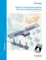
1. Introduction and Overview<br />
Vectra ® LCPs form a family of high performance<br />
resins based on patented Ticona technology. They are<br />
distinguished from other semi-crystalline resins by<br />
their long, rigid, rod-like molecules that are ordered<br />
even in the melt phase (Fig. 1.1).<br />
Fig. 1.1 · Representation of Structural Differences<br />
Between Liquid Crystal <strong>Polymers</strong> and<br />
Conventional Semi-Crystalline <strong>Polymers</strong><br />
Liquid Crystal Polymer<br />
Semi-Crystalline Polymer<br />
1<br />
Melt<br />
The unique melting behavior of LCPs has such a<br />
profound effect on properties and processing that<br />
we treat LCPs as a separate category of polymers<br />
(Table 1.1). Even so, they can be processed with all<br />
of the techniques common to more conventional<br />
thermoplastics including injection molding, extrusion,<br />
coextrusion, blow molding, etc.<br />
Nematic Structure<br />
Solid<br />
State<br />
Random Coil<br />
Vectra LCPs offer a balance of properties unmatched<br />
by most other resins. They are generally selected for<br />
a specific application or market sector based on a few<br />
key characteristics such as those shown in Table 1.2<br />
below. For instance, in molding electrical connectors,<br />
high flow in thin walls, dimensional stability at high<br />
temperatures and inherent flame retardance are the<br />
Extended Chain Structure<br />
• <strong>Hi</strong>gh Chain Continuity<br />
• <strong>Hi</strong>ghest Mechanical Properties<br />
Lamellar Structure<br />
• Low Chain Continuity<br />
• Good Mechanical Properties<br />
Table 1.1· Comparison of Amorphous, Semi-Crystalline, and Liquid Crystalline <strong>Polymers</strong><br />
Amorphous <strong>Polymers</strong><br />
No sharp melting point/soften gradually<br />
Random chain orientation in both solid and<br />
melt phase<br />
Do not flow as easily as semi-crystalline<br />
polymers in molding process<br />
Fiberglass and/or mineral reinforcement only<br />
slightly improves Deflection Temperature under<br />
Load (DTUL)<br />
Can give a transparent part<br />
Examples: cyclic olefinic copolymer,<br />
acrylonitrile-butadiene-styrene<br />
(ABS),<br />
polystyrene (PS),<br />
polycarbonate (PC),<br />
polysulfone (PSU), and<br />
polyetherimide (PEI)<br />
Semi-Crystalline <strong>Polymers</strong><br />
Relatively sharp melting point<br />
Ordered arrangement of chains of molecules<br />
and regular recurrence of crystalline structure<br />
only in solid phase<br />
Flow easily above melting point<br />
Reinforcement increases load bearing<br />
capabilities and DTUL considerably, particularly<br />
with highly crystalline polymers<br />
Part is usually opaque due to the crystal structure<br />
of semi-crystalline resin<br />
Examples: polyester (Impet ® and Celanex ®<br />
thermoplastic polyesters,<br />
Duranex PBT),<br />
polyphenylene sulfide (Fortron ® PPS),<br />
polyamide (Celanese ® nylon),<br />
polyacetal copolymer (Celcon ® POM,<br />
Hostaform ® POM, Duracon POM)<br />
Liquid Crystal <strong>Polymers</strong><br />
Melt over a range of temperatures;<br />
low heat of fusion<br />
<strong>Hi</strong>gh chain continuity; extremely ordered<br />
molecular structure in both melt phase and<br />
solid phase<br />
Flow extremely well under shear within<br />
melting range<br />
Reinforcement reduces anisotropy and<br />
increases load bearing capability and DTUL<br />
Part is always opaque due to the crystal<br />
structure of liquid crystal resin<br />
Examples: Vectra ® LCP<br />
9
Vectra ®<br />
liquid crystal polymer (LCP)<br />
key reasons for choosing an LCP. Key properties,<br />
such as high flow, stiffness and resistance to sterilizing<br />
radiation and sterilizing gases may make them<br />
candidates for surgical instruments. A number of<br />
Vectra LCP grades are USP Class VI compliant and<br />
meet ISO 10993 standards (see Section 3.5).<br />
The family of Vectra LCP resins is very easy to process<br />
in injection molding machines, which means<br />
short cycle times, high flow in thin sections and<br />
exceptional repeatability of dimensions. Molded parts<br />
exhibit very low warpage and shrinkage along with<br />
high dimensional stability, even when heated up to<br />
200-250°C.<br />
Vectra LCPs can be processed into thin films and<br />
multi-layer articles by conventional means, although<br />
some process development may be required. Film,<br />
sheet and laminates produced from Vectra LCPs<br />
exhibit excellent dimensional stability and exceptional<br />
barrier properties. In addition a special line of<br />
Vectran ® LCPs have been developed for superior<br />
properties at much thinner barrier layers to achieve<br />
the same or better barrier performance than layers<br />
made of ethyl vinyl alcohol (EVOH) or polyvinylidene<br />
chloride (PVDC). A wide range of market segments,<br />
i.e., food, beverage, packaging, medical, industrial, and<br />
electronics utilize LCPs. Many of the applications<br />
benefit from not only the barrier properties of LCPs<br />
but also from low coefficient of linear thermal<br />
expansion (CLTE), chemical resistance, high stiffness,<br />
and strength.<br />
New Vectra LCP compositions combine the consistency,<br />
stability, dimensional precision, and barrier<br />
properties of traditional wholly aromatic LCPs with<br />
processability at lower temperatures ranging from<br />
220°C to 280°C. The combination of properties of<br />
these new compositions makes them good candidates<br />
for use in moldings or laminates, and in blends with<br />
polyolefins, polycarbonate, and polyesters.<br />
The high strength-to-weight ratio of Vectra LCPs<br />
make the resins exceptional candidates for metal<br />
replacement applications. The maker of a needleless<br />
medical syringe estimated that injection molded LCP<br />
components were 75% lighter and 50% less costly<br />
than machined metal parts. Compared with less costly<br />
resins, easy-flowing Vectra LCPs cut molding<br />
cycles and many secondary operations to reduce the<br />
cost per part. In addition, many Vectra LCP compositions<br />
are listed by UL to allow the use of 50%<br />
regrind without loss of properties, enabling processors<br />
to improve cost competitiveness even further.<br />
Although and per pound or kilogram basis, they can<br />
appear expensive, on a price performance continuum,<br />
Vectra LCPs can be cost effective (Figure 1.2). For<br />
many applications exposed to high service stresses,<br />
Vectra LCPs are the preferred alternative to light<br />
metal alloys, thermosets and many other thermoplastics.<br />
Table 1.2 · Key Performance Characteristics by Market<br />
E/E Interconnects<br />
Good flow in thin walls<br />
Dimensional precision<br />
Heat resistance<br />
Flame retardance<br />
Healthcare<br />
Good flow in thin walls<br />
Chemical resistance<br />
Withstands sterilization<br />
Stiffness, strength<br />
Fiber Optics<br />
Dimensional Precision<br />
Excellent barrier properties<br />
Telecommunications<br />
Good flow in thin walls<br />
Dimensional precision<br />
Stiffness, strength<br />
Automotive<br />
Good flow in thin walls<br />
Solvent resistance<br />
Temperature resistance<br />
Dimensional stability<br />
Business machines<br />
Good flow in thin walls<br />
Dimensional precision<br />
Chemical resistance<br />
Packaging<br />
Excellent barrier properties<br />
Stiffness, strength<br />
Cryogenics<br />
Excellent barrier properties<br />
Good low temperature properties<br />
Stiffness, strength<br />
Audio/Video<br />
Good flow in thin walls<br />
Stiffness, strength<br />
Dimensional precision<br />
Temperature resistance<br />
10
Vectra ®<br />
liquid crystal polymer (LCP)<br />
Fig. 1.2 · Price Performance Comparison of Engineering and <strong>Hi</strong>gh Performance Plastics<br />
1<br />
PEEK<br />
PAS/PES<br />
PEI<br />
FP<br />
LCP<br />
Vectra<br />
AMORPHOUS<br />
PSU<br />
PPS-GF<br />
Fortron<br />
PA 4, 6<br />
Performance<br />
ABS<br />
PPO<br />
PET<br />
Impet<br />
PA6<br />
PBT<br />
Celanex<br />
Duranex<br />
POM<br />
Celcon<br />
Duracon<br />
Hostaform<br />
Kemetal<br />
PC<br />
SPS<br />
PA 6,6<br />
Celanese<br />
COC<br />
Topas<br />
PPS-MF<br />
Fortron<br />
PCT<br />
HTN<br />
PPA<br />
CRYSTALLINE<br />
Products available through Ticona<br />
Price<br />
* <strong>Hi</strong>gh Performance Plastics Acronyms<br />
ABS = acrylonitrile-butadiene-styrene HTN = high temperature polyamide (nylon)<br />
COC = cyclic olefin copolymer LCP = liquid crystal polymer<br />
FP = fluoropolymers PA6,6 = polyamide 6,6 (nylon)<br />
PA6 = polyamide 6 (nylon) PAS = polyaryl sulfone<br />
PA4,6 = polyamide 4,6 (nylon) PCT = polycyclohexylenedimethylene terephthalate<br />
PBT = polybutylene terephthalate PEI = polyether imide<br />
PEEK = polyether ether ketone PET = polyethylene terephthalate<br />
PES = polyether sulfone PPO = modified polyphenylene oxide<br />
POM = polyoxymethylene (polyacetal) PPS-GF = polyphenylene sulfide (glass filled)<br />
PPS-MF = polyphenylene sulfide (mineral filled) PSU = polysulfone<br />
PPA = polyphthalamide PC = polycarbonate<br />
SPS = syndiotactic polystyrene<br />
11
Vectra ®<br />
liquid crystal polymer (LCP)<br />
2. Vectra ® LCP Product Line<br />
The Vectra LCP product line is built around a number<br />
of base polymers of varying compositions. The<br />
base polymers differ in their high temperature performance,<br />
rigidity, toughness and flow characteristics.<br />
Ticona is continuously developing new polymers to<br />
tailor the composition to a specific need.<br />
Each of these compositions can be used without<br />
modification for extrusion or injection molding applications.<br />
Care should be taken when using unfilled<br />
polymers for injection molding since fibrillation of<br />
the oriented surface can occur. In addition, the base<br />
polymers can be compounded with various fillers and<br />
reinforcements to provide the necessary balance of<br />
thermal, mechanical, tribological or environmental<br />
properties for the specific application or market need.<br />
Figure 2.1 explains the product nomenclature and<br />
surveys the Vectra LCP grades currently available.<br />
2.1 Grade Descriptions<br />
2.1.1 Glass fiber reinforced grades (100-series)<br />
Reinforcement with glass fibers increases rigidity,<br />
mechanical strength and heat resistance. At the same<br />
time, the degree of anisotropy is reduced. Vectra LCPs<br />
are available with 15%, 30%, 40% or 50% glass fiber.<br />
Examples: Vectra E130i (30% glass fiber), Vectra<br />
A130 (30% glass fiber), Vectra B130 (30% glass<br />
fiber), Vectra C150 (50% glass fiber), Vectra L140<br />
(40% glass fiber), etc.<br />
2.1.2 Carbon fiber reinforced grades (200-series)<br />
Reinforcement with carbon fibers gives higher<br />
rigidity than with glass fibers. At the same time, the<br />
carbon fiber reinforced compositions have a lower<br />
density than the glass fiber grades with the same filler<br />
content. Carbon fiber reinforced polymers are used<br />
where the highest possible stiffness is required.<br />
Note also that carbon fiber reinforced grades are<br />
conductive.<br />
Examples: Vectra A230 (30% carbon fiber), Vectra<br />
B230 (30% carbon fiber)<br />
2.1.3 Filler/fiber combinations (400-series)<br />
Products with various filler and fiber combinations<br />
comprise the 400-series. The PTFE and graphite<br />
modified grades are used for bearing and wear resistant<br />
applications. The titanium dioxide modified<br />
grade has high light reflectance.<br />
Examples: Vectra A430 (PTFE), Vectra A435 (glass<br />
fiber, PTFE)<br />
2.1.4 Mineral filled grades (500-series)<br />
The mineral filled grades typically have high impact<br />
strength relative to the glass fiber reinforced grades.<br />
They have good flow and a good surface finish.<br />
Selected Vectra polymers are available with 15%,<br />
30%, 40% or 50% mineral.<br />
Examples: Vectra A515 (15% mineral), Vectra E530i<br />
(30% mineral), Vectra C550 (50% mineral)<br />
2.1.5 Graphite filled grades (600-series)<br />
Graphite flake provides some added lubricity and<br />
exceptionally good hydrolytic stability and chemical<br />
resistance.<br />
Example: Vectra A625 (25% graphite)<br />
2.1.6 Specialty grades (700 and 800-series)<br />
The grades in the 700 series are modified with an<br />
electrically conductive carbon black and are good<br />
candidates for electrostatic dissipation.<br />
Examples: Vectra A700 (glass fiber, conductive carbon<br />
black), Vectra A725 (graphite, PTFE, conductive<br />
carbon black)<br />
The 800 series grades have applications in electroless<br />
plating, EMI/RFI shielding, printed circuit boards<br />
and MID-components with integrated circuits.<br />
Examples: Vectra C810 (glass, mineral) and Vectra<br />
E820i (mineral)<br />
12
Vectra ®<br />
liquid crystal polymer (LCP)<br />
Fig. 2.1 · Vectra ® LCP Product Line<br />
Base Resin Series A B C D Ei H L T<br />
Unreinforced Polymer A950 B950 C950<br />
2<br />
Glass fiber reinforced A115 C115<br />
A130 B130 C130 D130M E130i H130 L130 T130<br />
H140 L140<br />
A150<br />
C150<br />
Carbon fiber reinforced A230 B230<br />
PTFE modified<br />
Mixed filler/fiber<br />
A430<br />
A435<br />
A410<br />
Mineral modified A515 E530i<br />
A530<br />
C550<br />
Graphite<br />
A625<br />
Conductive (ESD) grades A700<br />
A725<br />
Metallization (e.g. MID) C810 E820i<br />
E820iPd<br />
Vectra LCP<br />
A-Polymer<br />
B-Polymer<br />
C-Polymer<br />
D-Polymer<br />
- Industry Standard<br />
- <strong>Hi</strong>ghest stiffness<br />
- Standard polymer,<br />
good flow<br />
- Encapsulated grade<br />
H-Polymer<br />
L-Polymer<br />
T-Polymer<br />
- <strong>Hi</strong>ghest temperature<br />
capability<br />
- <strong>Hi</strong>gh flow,<br />
balanced properties<br />
- New maximum temperature<br />
capability<br />
E(i)-Polymer<br />
- Easiest flow,<br />
high temperature<br />
13
Vectra ®<br />
liquid crystal polymer (LCP)<br />
2.2 Colors<br />
The natural color of Vectra LCPs is ivory or beige.<br />
Graphite, carbon black and carbon fiber filled grades<br />
are correspondingly black or anthracite in color.<br />
Vectra LCPs can be colored in order to identify or<br />
differentiate between components. However, Vectra<br />
LCPs do not lend themselves to “color matching”.<br />
Color master batches (or concentrates) with a high<br />
pigment loading are available in a wide array of<br />
colors (Table 2.1). These master batches are supplied<br />
as pellets and are used for melt coloring of natural<br />
Vectra LCP grades during processing.<br />
Color master batches are available in both Vectra “A”<br />
and Vectra “Ei” polymer bases and all are cadmium<br />
free. Color master batch Vectra A9500 should be used<br />
to color Vectra A, B, C, or L grades. Color master<br />
batch Vectra E9500i should be used to color Vectra<br />
Ei or H grades.<br />
The last two digits at the end of the master batch<br />
code denote the recommended mix ratio of natural<br />
pellets to color master batch, e.g.:<br />
VJ3040K10 = 10:1<br />
VA3031K20 = 20:1<br />
Lower concentrations are possible if the color effect<br />
achieved is satisfactory. <strong>Hi</strong>gher concentrations of<br />
master batch are not recommended because of a<br />
potential decrease in mechanical properties or flow<br />
at higher loading.<br />
2.3 Packaging<br />
The standard package is a 20/25 kg bag although<br />
boxes and gaylords are available under some circumstances.<br />
Table 2.1 · Available Color Master Batches<br />
Vectra Vectra Vectra<br />
A9500 E9500i A9500/E9500i<br />
Stock number Stock number Color number Standard Letdown Color<br />
VC0006 VC0019 VD3003K20 20:1 Black<br />
VC0010 VC0027 VA3031K20 20:1 White<br />
VC0004 VC0030 VG3010K20 20:1 Blue<br />
VC0016 VC0031 VJ3040K10 10:1 Emerald green<br />
VC0009 VC0028 VL3021K10 10:1 Yellow<br />
VC0008 VC0032 VS3033K10 10:1 Pink<br />
VC0011 VC0026 VS3035K10 10:1 Red<br />
14
Vectra ®<br />
liquid crystal polymer (LCP)<br />
3. Physical Properties<br />
The properties of Vectra ® LCPs are influenced to a<br />
high degree by its liquid crystal structure. The rod<br />
shaped molecules are oriented in the flow direction<br />
during injection molding or extrusion. Due to the<br />
highly ordered nature of LCPs, the mechanical<br />
properties, shrinkage and other part characteristics<br />
depend upon the flow pattern in the part. During<br />
mold filling, the “fountain flow” effect causes the<br />
molecules on the surface to be stretched in the flow<br />
direction. Ultimately, these molecules are located on<br />
the surface of the part, which results in a skin that is<br />
highly oriented in the flow direction (15-30% of the<br />
part's total thickness) (Figure 3.0). This molecular<br />
orientation causes a self-reinforcement effect giving<br />
exceptional flexural strength and modulus as well as<br />
good tensile performance. For example, a commonly<br />
used, 30% glass reinforced LCP, Vectra A130, has<br />
strength and stiffness about 50% higher than that of<br />
comparable 30% glass reinforced engineering resins.<br />
Vectra LCPs belong to the Ticona family of high<br />
performance engineering resins. It is a rigid, tough<br />
material with excellent heat resistance. A summary of<br />
short-term properties for the majority of commer-<br />
cially available Vectra LCP grades can be found in the<br />
Short-Term Properties brochure. Please check with<br />
your local Vectra LCP representative for availability<br />
of additional grades.<br />
All properties given in the Short-Term Properties<br />
brochure were measured on standard injection<br />
molded test specimens and can be used for grade<br />
comparison. Their applicability to finished parts is<br />
limited because the strength of a component depends<br />
to a large extent on its design.<br />
The level of properties depends on the type of filler<br />
or reinforcement used. Glass fibers impart increased<br />
stiffness, tensile strength and heat deflection temperature.<br />
Carbon fibers give the highest stiffness. The<br />
addition of mineral fillers improves stiffness and<br />
provides increased toughness and a smoother surface<br />
compared to glass reinforced. Graphite improves<br />
elongation at break and provides added lubricity.<br />
PTFE modified grades have excellent sliding and<br />
wear properties. The impact strength of unfilled<br />
Vectra LCPs is reduced by the addition of fillers and<br />
reinforcements, but is still relatively high.<br />
2<br />
3<br />
Fig. 3.0 · Fracture Surface of Unfilled Vectra LCP<br />
15
Vectra ®<br />
liquid crystal polymer (LCP)<br />
3.1 Mechanical properties<br />
3.1.1 Effect of anisotropy and wall thickness<br />
LCPs are well known to have anisotropic properties<br />
when molded into parts. A result of this is a tendency<br />
to fibrillate when abraded. Unlike other<br />
engineering or technical polymers, LCPs become<br />
much less anisotropic as they are formulated with<br />
glass fiber reinforcement, and to a lesser degree with<br />
mineral. An example comparing Vectra LCPs with a<br />
conventional engineering resin, PBT, both with and<br />
without glass reinforcement is shown in Figure 3.1.1.<br />
The anisotropy of 30% glass reinforced Vectra LCP<br />
and 30% glass reinforced PBT is nearly the same<br />
indicating that designing for glass reinforced Vectra<br />
and other engineering resins need not be impacted by<br />
anisotropy. Management of anisotropy can be affected<br />
by gate location and wall thickness adjustments.<br />
Fig. 3.1.1 · Comparison of Anisotropy*<br />
of Vectra ® LCP versus PBT<br />
(ISO universal test specimen)<br />
Table 3.1.1 · Anisotropy of Properties – 2 mm thick<br />
Unfilled 30% glass 30% mineral<br />
filled filled<br />
Flex strength Ratio FD/TD* 2.7 2.1 2.4<br />
Flex modulus Ratio FD/TD* 3.6 2.9 3.9<br />
Tensile strength Ratio FD/TD* 2.3 1.9 2.5<br />
Tensile modulus Ratio FD/TD* 3.3 2.2 2.7<br />
*FD/TD = anisotropy ratio – flow direction/transverse direction<br />
Table 3.1.2 · Anisotropy of Properties – 1 mm thick<br />
Unfilled 30% glass 30% mineral<br />
filled filled<br />
Flex strength Ratio FD/TD* 3.9 3.1 2.9<br />
Flex modulus Ratio FD/TD* 6.7 4.4 4.8<br />
Tensile strength Ratio FD/TD* 3.6 2.6 3.1<br />
Tensile modulus Ratio FD/TD* 3.0 2.5 2.8<br />
*FD/TD = anisotropy ratio – flow direction/transverse direction<br />
Anisotropy Ratio (FD/TD*)<br />
3.0<br />
2.5<br />
2.0<br />
1.5<br />
1.0<br />
0.5<br />
Fig. 3.1.2 · Micrograph of Fiber Structure<br />
showing Orientation of Outer Layers.<br />
0<br />
PBT<br />
30%GF PBT LCP 30%GF LCP<br />
* Tensile strength in flow direction/<br />
tensile strength in transverse direction<br />
Table 3.1.1 compares the anisotropy of flexural and<br />
tensile properties of various Vectra LCP grades<br />
molded in a 80 mm x 80 mm x 2 mm flat plate mold.<br />
Table 3.1.2 shows the effect of molding in a thinner<br />
part (80 mm x 80 mm x 1 mm) on the anisotropy<br />
ratio.<br />
As the wall, film or sheet thickness decreases, the<br />
highly oriented outer layer becomes a higher percentage<br />
of the total (Figure 3.1.2) thickness. This<br />
higher percentage of highly oriented surface layer,<br />
in general, results in greater strength and modulus<br />
in thinner sections (Figures 3.1.3, 3.1.4, 3.1.5, 3.1.6).<br />
The excellent flow characteristics of Vectra LCPs<br />
enable the filling of extremely thin walls to take<br />
advantage of this stiffness and strength.<br />
Strand LCP extrudate shows the higher orientation in<br />
the outer ”skin” layer but not in the core;<br />
Extruded LCP fiber is highly oriented with all ”skin” observed.<br />
16
Vectra ®<br />
liquid crystal polymer (LCP)<br />
Fig. 3.1.3 · Tensile Modulus versus Wall Thickness Vectra LCP<br />
Tensile Modulus, MPa<br />
50,000<br />
40,000<br />
30,000<br />
20,000<br />
10,000<br />
0.8 mm<br />
1.6 mm<br />
3.2 mm<br />
4.0 mm<br />
0<br />
B130<br />
E130i<br />
H140<br />
A130<br />
A530<br />
L130<br />
B230<br />
3<br />
Fig. 3.1.4 · Tensile Strength versus Wall Thickness Vectra LCP<br />
Tensile Strength, MPa<br />
300<br />
200<br />
100<br />
0.8 mm<br />
1.6 mm<br />
3.2 mm<br />
4.0 mm<br />
0<br />
B130<br />
E130i<br />
H140<br />
A130<br />
A530<br />
L130<br />
B230<br />
Fig. 3.1.5 · Flexural Modulus versus Wall Thickness Vectra LCP<br />
Flexural Modulus, MPa<br />
40,000<br />
30,000<br />
20,000<br />
10,000<br />
0.8 mm<br />
1.6 mm<br />
3.2 mm<br />
4.0 mm<br />
0<br />
B130<br />
E130i<br />
H140<br />
A130<br />
A530<br />
L130<br />
B230<br />
Fig. 3.1.6 · Flexural Strength versus Wall Thickness Vectra LCP<br />
Flexural Strength, MPa<br />
400<br />
300<br />
200<br />
100<br />
0.8 mm<br />
1.6 mm<br />
3.2 mm<br />
4.0 mm<br />
0<br />
B130<br />
E130i<br />
H140<br />
A130<br />
A530<br />
L130<br />
B230<br />
17
Vectra ®<br />
liquid crystal polymer (LCP)<br />
3.1.2 Short term stress<br />
The tensile stress strain curves shown in Figure 3.1.7<br />
are representative of the Vectra LCP product line.<br />
Vectra A130 is a 30% glass filled resin, Vectra B230<br />
is a 30% carbon fiber reinforced resin, Vectra A430 is<br />
a 25% PTFE filled resin, Vectra L130 is a 30% glass<br />
filled resin, Vectra H140 is a 40% glass filled resin.<br />
These five products essentially cover the range of<br />
elongation (strain) for filled or reinforced Vectra LCP<br />
grades. Like most other filled or reinforced semicrystalline<br />
plastics, Vectra LCPs have no yield point.<br />
Even unfilled LCPs have no yield point.<br />
Fig. 3.1.7 · Stress Strain Curves at 23°C<br />
Stress (MPa)<br />
250<br />
200<br />
150<br />
100<br />
50<br />
Fig. 3.1.8a · Influence of Temperature on<br />
Stress Strain Behavior, Vectra B230<br />
0<br />
-40°C<br />
23°C<br />
200°C<br />
80°C<br />
120°C<br />
0 0.2 0.4 0.6 0.8 1.0 1.2 1.4 1.6<br />
Strain (%)<br />
Stress (MPa)<br />
250<br />
200<br />
150<br />
100<br />
50<br />
0<br />
B230<br />
H140<br />
L130<br />
A130<br />
A430<br />
0 1.0 2.0 3.0 4.0 5.0 6.0 7.0<br />
Strain (%)<br />
Stress (MPa)<br />
250<br />
200<br />
150<br />
100<br />
50<br />
Fig. 3.1.8b · Influence of Temperature on<br />
Stress Strain Behavior, Vectra E130i<br />
200°C<br />
80°C<br />
120°C<br />
-40°C<br />
23°C<br />
As with any thermoplastic resin, stiffness and strength<br />
of the materials decrease with increasing temperature.<br />
Figures 3.1.8a and b show the influence of temperature<br />
on the tensile stress strain curves of Vectra B230<br />
(carbon fiber filled, high strength and stiffness), and<br />
Vectra E130i (glass fiber filled, high temperature).<br />
0<br />
0 0.2 0.4 0.6 0.8 1.0 1.2 1.4 1.6 1.8<br />
Strain (%)<br />
The influence of temperature on tensile properties for<br />
a number of Vectra LCP grades is given in Figures<br />
3.1.9 and 3.1.10.<br />
Fig. 3.1.9 · Tensile Modulus versus Temperature, Vectra LCP<br />
Tensile Modulus (MPa)<br />
40,000<br />
30,000<br />
20,000<br />
10,000<br />
-40°C<br />
23°C<br />
80°C<br />
120°C<br />
200°C<br />
250°C<br />
0<br />
A530<br />
B130 B230 E130i E530i L130 H140<br />
18
Vectra ®<br />
liquid crystal polymer (LCP)<br />
Fig. 3.1.10 · Tensile Strength versus Temperature, Vectra LCP<br />
250<br />
Tensile Strength (MPa)<br />
200<br />
150<br />
100<br />
-40°C<br />
23°C<br />
80°C<br />
120°C<br />
200°C<br />
250°C<br />
50<br />
3<br />
0<br />
A530<br />
B130 B230 E130i E530i L130 H140<br />
3.1.3 Behavior under long term stress<br />
Vectra LCPs have good resistance to creep. Figures<br />
3.1.11 and 3.1.12 show the tensile creep modulus of<br />
two high temperature resins, Vectra E130i and Vectra<br />
H140, for exposure at 23°C and 120°C at various<br />
stress levels. The maximum exposure time was 1,000<br />
hours for E130i and 1,500 hours for H140. The stress<br />
levels were chosen to be 30% of the short-term failure<br />
stress and none of the samples failed in testing.<br />
No sign of creep rupture – a common form of failure<br />
– was observed at stress levels below 30%.<br />
Figures 3.1.13, 3.1.14 and 3.1.15 show flexural creep<br />
modulus for Vectra A130, Vectra B130, and Vectra<br />
C130 – all 30% fiberglass reinforced resins.<br />
Fig. 3.1.12 · Tensile Creep Modulus, Vectra H140<br />
Tensile Creep Modulus (MPa)<br />
120°C/30 MPa<br />
24,000<br />
20,000<br />
16,000<br />
23°C/30 MPa<br />
23°C/40 MPa<br />
12,000<br />
8,000<br />
120°C/20 MPa<br />
1 10<br />
10 2 10 3 10 4<br />
4,000<br />
120°C/40 MPa<br />
0<br />
Time (hours)<br />
Fig. 3.1.11 · Tensile Creep Modulus , Vectra E130i<br />
16,000<br />
Fig. 3.1.13 · Flexural Creep Modulus, Vectra A130<br />
20,000<br />
14,000<br />
23°C/40 MPa<br />
15,000<br />
23°C<br />
Tensile Creep Modulus (MPa)<br />
12,000<br />
10,000<br />
8,000<br />
6,000<br />
4,000<br />
23°C/30 MPa<br />
120°C/20 MPa 120°C/30 MPa<br />
120°C/40 MPa<br />
Flexural Creep Modulus (MPa)<br />
10,000<br />
8,000<br />
6,000<br />
4,000<br />
2,000<br />
80°C<br />
120°C<br />
2,000<br />
0<br />
1 10 10 2<br />
10 3<br />
Time (hours)<br />
Maximum Stress = 50 MPa<br />
1,000<br />
10 -2 10 -1 1 10 10 2 10 3<br />
Time (hours)<br />
19
Vectra ®<br />
liquid crystal polymer (LCP)<br />
Fig. 3.1.14 · Flexural Creep Modulus, Vectra B130<br />
3.1.5 Fatigue<br />
Flexural Creep Modulus (MPa)<br />
30,000<br />
20,000<br />
10,000<br />
8,000<br />
6,000<br />
4,000<br />
3,000<br />
2,000<br />
Maximum Stress = 50 MPa<br />
23°C<br />
80°C<br />
Components subject to periodic stress must be designed<br />
on the basis of fatigue strength, i.e. the cyclic<br />
stress amplitude a determined in the fatigue test – at<br />
a given mean stress m – which a test specimen withstands<br />
without failure over a given number of stress<br />
cycles, e.g. 10 7 (Wöhler curve). The various stress<br />
ranges in which tests of this nature are conducted are<br />
shown in Figure 3.1.16<br />
Fig. 3.1.16 · Stress Ranges in Fatigue Tests<br />
1,000<br />
10 -2 10 -1 1 10 10 2 10 3<br />
Time (hours)<br />
Fig. 3.1.15 · Flexural Creep Modulus, Vectra C130<br />
30,000<br />
20,000<br />
+ <br />
– <br />
m > a<br />
u = 0<br />
m = a<br />
range for<br />
fluctuating stresses<br />
(under compression)<br />
m < a<br />
m = 0<br />
m ≥ a m ≥ a m ≥ a<br />
m > a<br />
range for<br />
fluctuating stresses<br />
compression<br />
– + tension<br />
m = a<br />
u = 0<br />
m > a<br />
time<br />
range for<br />
fluctuating stresses<br />
(under tension)<br />
Flexural Creep Modulus (MPa)<br />
23°C<br />
10,000<br />
8,000<br />
80°C<br />
6,000<br />
4,000<br />
120°C<br />
3,000<br />
2,000<br />
Maximum Stress = 50 MPa<br />
1,000<br />
10 -2 10 -1 1 10 10 2 10 3<br />
Time (hours)<br />
For most plastics, the fatigue strength after 10 7 stress<br />
cycles is about 20 to 30% of the ultimate tensile<br />
strength determined in the tensile test. It decreases<br />
with increasing temperature, stress cycle frequency<br />
and the presence of stress concentration peaks in<br />
notched components.<br />
The Wöhler flexural fatigue stress curves for three<br />
Vectra LCP grades are shown in Figure 3.1.17. The<br />
flexural fatigue strength of Vectra A130 after 10 7<br />
stress cycles is bw = 50 N/mm 2 .<br />
3.1.4 Notch sensitivity (Impact testing)<br />
Vectra LCPs have very high notched and unnotched<br />
Charpy and Izod impact strength because of the<br />
wood like fibrous structure. If this fibrous structure<br />
is cut by notching, as in a notched Izod or Charpy<br />
specimen, the energy to break is still high compared<br />
with other glass reinforced resins.<br />
The values for notched and unnotched impact are<br />
reported in the Short-Term Properties brochure.<br />
Fig. 3.1.17 · Wöhler Curves for Vectra, longitudinal<br />
direction determined in the alternating flexural<br />
stress range<br />
Stress amplitude ± a (MPa)<br />
120<br />
100<br />
80<br />
60<br />
40<br />
20<br />
0<br />
10 3 10 5 10 6 10 7<br />
Number of stress cycles N<br />
10 4 A130<br />
test temperature 23°C<br />
stress cycle frequency 10 Hz<br />
mean stress m = 0<br />
B230<br />
20
Vectra ®<br />
liquid crystal polymer (LCP)<br />
3.1.6 Tribological properties<br />
The friction and wear characteristics of Vectra LCPs<br />
are very specific to the application. In general, Vectra<br />
resins have performed satisfactorily in low load friction<br />
and wear applications. Typical wear grades of<br />
Vectra LCPs contain PTFE, carbon fibers, graphite,<br />
or a combination of these and other fillers and<br />
reinforcements. Coefficients of friction typically<br />
range from 0.1 to 0.2. More specific data are available<br />
with standardized tests (Table 3.1.3). However, we<br />
recommend that your specific bearing, friction and<br />
wear applications be reviewed with Vectra LCP technical<br />
service engineers.<br />
Table 3.1.3 · Coefficient of Friction, µ, of<br />
Vectra ® LCP (ASTM D1894)<br />
Description Vectra LCP Coefficient of Friction –<br />
Grade Flow Direction<br />
Static Dynamic<br />
A115 0.11 0.11<br />
Glass Fiber Reinforced A130 0.14 0.14<br />
A150 0.16 0.19<br />
Carbon Fiber Reinforced A230 0.19 0.12<br />
Mixed Filler/Fiber A410 0.21 0.21<br />
PTFE Modified<br />
A430 0.16 0.18<br />
A435 0.11 0.11<br />
Mineral Modified A515 0.20 0.19<br />
Graphite A625 0.21 0.15<br />
Carbon Fiber Reinforced B230 0.14 0.14<br />
Glass Fiber Reinforced L130 0.15 0.16<br />
Figure 3.1.18 compares the dynamic coefficient of<br />
friction, µ, of a number of Vectra LCP grades sliding<br />
against steel to that of acetal or POM. The figure also<br />
shows the wear while dry sliding on a rotating steel<br />
shaft.<br />
A430<br />
POM<br />
A435<br />
A625<br />
B230<br />
A530<br />
A230<br />
B130<br />
A130<br />
C130<br />
0.4<br />
3.1.7 Damping<br />
Fig. 3.1.18 · Friction and Wear<br />
0.3 0.2 0.1 0 5 10 15<br />
Dynamic coefficient<br />
Wear* (mm 3 )<br />
of friction µ*<br />
*average from longitudinal and transverse to flow direction<br />
Friction: steel ball diameter 13 mm,<br />
load F N = 6 N, sliding speed v = 60 cm/min.<br />
Wear: roughness height = 0.1 µm,<br />
peripheral speed of the shaft v = 136 m/min,<br />
load F N = 3 N, duration of test 60 hr<br />
The unique structural characteristics of Vectra LCPs<br />
greatly affect the damping characteristics. Generally<br />
speaking, materials with high modulus, such as metals,<br />
have low damping (internal loss) characteristics and<br />
low modulus materials, such as rubbers, have high<br />
damping characteristics. Vectra LCPs, however, exhibit<br />
high damping characteristics despite their high<br />
modulus. This is due to the rigid rod like crystalline<br />
structure of the LCP.<br />
The relationship between internal loss, , and<br />
damping factor, , is as follows:<br />
T/ = <br />
where T = cycle and = 3.14.<br />
3<br />
21
Vectra ®<br />
liquid crystal polymer (LCP)<br />
Figure 3.1.19 shows the damping properties of<br />
various materials. Figure 3.1.20 compares the vibration<br />
characteristics of Vectra LCP grades.<br />
Damping Factor (1/sec)<br />
14<br />
12<br />
10<br />
Tensile Modulus (GPa)<br />
8<br />
100<br />
80<br />
60<br />
40<br />
20<br />
10<br />
8<br />
6<br />
4<br />
2<br />
Fig. 3.1.19 · Damping Properties<br />
Aluminum<br />
PBT<br />
POM<br />
PE<br />
Vectra A230<br />
1<br />
0 0.02 0.04 0.06 0.08 0.10 0.20<br />
Internal loss<br />
Vectra A950<br />
6<br />
0 10,000 20,000<br />
Flexural Modulus (MPa)<br />
Rubber<br />
Fig. 3.1.20 · Vibration Characteristics<br />
A950<br />
A430<br />
C810<br />
A130<br />
C130<br />
A410<br />
A230<br />
B230<br />
30,000<br />
3.2 Thermal properties<br />
3.2.1 Dynamic mechanical spectra<br />
A snapshot view of the thermomechanical behavior<br />
of plastic materials is provided by Dynamic Mechanical<br />
Analysis (DMA). This technique is used to<br />
scan the storage modulus or stiffness (E’), loss modulus<br />
(E’’) and damping or energy dissipation (tan )<br />
behavior of a material over a wide temperature range.<br />
The stiffness or modulus (E’) corresponds to, and has<br />
nearly the exact value as, the conventional tensile<br />
modulus (E) in temperature regions of low loss or<br />
damping factor. This modulus represents the recoverable<br />
elastic energy stored in a viscoelastic<br />
material during deformation. The damping factor<br />
(tan ) represents the energy losses occurring during<br />
deformation due to internal molecular friction that<br />
occurs in a viscoelastic material.<br />
By comparing DMA curves of two or more Vectra<br />
LCPs (Figures 3.2.1-3.2.8), retention of stiffness as<br />
temperatures are raised is easily compared. Generally<br />
the higher the stiffness at any temperature, the more<br />
creep resistant the variants will be at that temperature.<br />
In Table 3.2.1 the temperature where the modulus has<br />
fallen to 50% of the ambient temperature modulus<br />
value is tabulated for a series of Vectra LCPs.<br />
Generally, the higher this temperature, the more creep<br />
resistant the variant will be at elevated temperatures.<br />
For example, Vectra A130 (T 1/2E = 208ºC) will be<br />
more creep resistant than Vectra A530 (T 1/2E = 126ºC)<br />
in the temperature range of about 120 to 210ºC.<br />
Likewise, Vectra E130i (T 1/2E = 282ºC) will be more<br />
creep resistant than Vectra A130 (T 1/2E = 208ºC) in the<br />
210 to 280ºC temperature range.<br />
Similarly, peaks in the tan indicate transitions and<br />
temperature ranges where the polymer will be more<br />
energy-dissipating (note that the frequency of the<br />
measurements is very, very low, on the order of one<br />
hertz [cycle/second]. This frequency is well below<br />
the audible sound range of 20-20,000 hertz. Typically,<br />
Vectra polymers have two strong damping peaks<br />
at the glass transition, , and at a lower temperature<br />
transition, . These are tabulated in Table 3.2.1.<br />
Typically, the damping peaks for all Vectra LCPs fall<br />
over a wide range of temperature. Glassy transitions<br />
are usually in the 120 to 155ºC range with the lower<br />
temperature secondary loss peak at 10 to 80ºC. In<br />
general, the temperatures of the damping peaks at just<br />
above ambient make Vectra LCPs good sound<br />
absorbers. When struck, they do not “ring”, they<br />
“clunk” or sound “dead”.<br />
22
Vectra ®<br />
liquid crystal polymer (LCP)<br />
Table 3.2.1 · Dynamic Mechanical Analysis<br />
Sample ID transition transition Modulus E Half Modulus<br />
(T g ) (°C) (°C) at 23°C Temperature<br />
(MPa) T 1/2E (°C)<br />
Vectra A130 119 54 5100 208<br />
Vectra A530 119 50 5000 126<br />
Vectra B130 157 72 5700 189<br />
Vectra B230 159 79 5900 216<br />
Vectra E130i 135 23 4300 282<br />
Vectra E530i 130 22 4100 204<br />
Vectra H140 130 16 5200 290<br />
Vectra L130 130 11 5200 238<br />
Tensile Moduli (MPa)<br />
Fig. 3.2.3 · Dynamic Mechanical Analysis<br />
Vectra B130<br />
10 4<br />
10 3<br />
10 2<br />
10 1 -50 0 50 100 150 200<br />
E’<br />
tan<br />
E’’<br />
250<br />
<br />
300<br />
10 0<br />
10 -1<br />
350 10-2<br />
Temperature (°C)<br />
tan <br />
3<br />
Fig. 3.2.1 · Dynamic Mechanical Analysis<br />
Vectra A130<br />
Fig. 3.2.4 · Dynamic Mechanical Analysis<br />
Vectra B230<br />
Tensile Moduli (MPa)<br />
10 4<br />
10 0<br />
10 3<br />
E’<br />
tan <br />
10 -1<br />
E’’<br />
10 2<br />
10 1 -50 0 50 100 150 200 250 300 350 10-2<br />
Temperature (°C)<br />
tan <br />
Tensile Moduli (MPa)<br />
10 4<br />
10 0<br />
10 3<br />
E’<br />
tan <br />
10 -1<br />
E’’<br />
10 2<br />
10 1 -50 0 50 100 150 200 250 300 350 10-2<br />
Temperature (°C)<br />
tan <br />
Fig. 3.2.2 · Dynamic Mechanical Analysis<br />
Vectra A530<br />
Fig. 3.2.5 · Dynamic Mechanical Analysis<br />
Vectra E130i<br />
Tensile Moduli (MPa)<br />
10 4<br />
10 0<br />
10 3<br />
tan <br />
E’<br />
10 -1<br />
10 2<br />
E’’<br />
10 1 -50 0 50 100 150 200 250 300 350 10-2<br />
Temperature (°C)<br />
tan <br />
Tensile Moduli (MPa)<br />
10 4<br />
10 0<br />
E’<br />
10 3<br />
tan <br />
10 -1<br />
E’’<br />
10 2<br />
10 1 -50 0 50 100 150 200 250 300 350 10-2<br />
Temperature (°C)<br />
tan <br />
23
Vectra ®<br />
liquid crystal polymer (LCP)<br />
Tensile Moduli (MPa)<br />
Tensile Moduli (MPa)<br />
Tensile Moduli (MPa)<br />
Fig. 3.2.6 · Dynamic Mechanical Analysis<br />
Vectra E530i<br />
10 4<br />
10 0<br />
tan <br />
10 3<br />
10 -1<br />
E’<br />
10 2<br />
E’’<br />
10 1 -50 0 50 100 150 200 250 300 350 10-2<br />
Temperature (°C)<br />
Fig. 3.2.7 · Dynamic Mechanical Analysis<br />
Vectra H140<br />
10 4<br />
10 3<br />
10 2<br />
10 1 -50 0 50 100 150 200<br />
tan<br />
250<br />
<br />
300<br />
10 0<br />
E’<br />
10 -1<br />
E’’<br />
350 10-2<br />
Temperature (°C)<br />
Fig. 3.2.8 · Dynamic Mechanical Analysis<br />
Vectra L130<br />
10 4<br />
10 3<br />
10 2<br />
10 1 -50 0 50 100 150 200<br />
tan <br />
250<br />
E’<br />
E’’<br />
300<br />
10 0<br />
10 -1<br />
350 10-2<br />
Temperature (°C)<br />
tan <br />
t an <br />
tan <br />
3.2.2 Deflection temperature under load<br />
The Deflection Temperature under Load (DTUL/<br />
HDT) measured at 1.8 MPa for Vectra LCPs ranges<br />
from 120°C for an unreinforced, low temperature<br />
product to 300°C for the glass fiber reinforced high<br />
heat products. Although values for DTUL can be<br />
measured at loads of 8 MPa, 1.8 MPa and 0.45 MPa,<br />
values are most frequently reported for crystalline materials<br />
at 1.8 MPa. This value is provided for all Vectra<br />
LCP grades in the Short-Term Properties brochure.<br />
3.2.3 Coefficient of linear thermal expansion<br />
One of the advantages of Vectra LCPs are its very<br />
low coefficient of linear thermal expansion (CLTE) in<br />
comparison with other thermoplastics. The expansion<br />
coefficient displays marked anisotropy. It is much<br />
lower in the orientation direction than the cross flow<br />
direction. With very high orientation in the flow<br />
direction, the expansion coefficient may even be<br />
negative, especially for carbon fiber reinforced grades.<br />
The expansion coefficient of Vectra LCPs can be<br />
varied within certain limits and matched to the<br />
expansion coefficient of glass, steel, ceramic, or glass<br />
fiber/epoxy substrates. Figure 3.2.9 compares the<br />
expansion coefficients of various engineering materials.<br />
When composite structures of Vectra LCPs and<br />
other materials are heated, no thermally induced<br />
stresses occur because the thermal expansion values<br />
are similar. Components for surface mounting should<br />
have expansion coefficients closely in line with those<br />
of the circuit board substrate (usually FR 4 epoxy<br />
resin/glass fiber) to avoid mechanical stresses at the<br />
soldering points as a result of thermal loading. Vectra<br />
LCPs are therefore a good material to consider for<br />
composite structures, particularly for surface mount<br />
technology (SMT) components.<br />
The expansion coefficient is dependent on the flowinduced<br />
orientation in the part. The more balanced<br />
the flow through a given section of the part, the more<br />
balanced the expansion coefficient in the flow and the<br />
cross flow directions. Table 3.2.2 compares the expansion<br />
coefficient of select Vectra LCP grades in two<br />
geometries.<br />
As shown in Figure 3.2.10 the orientation in the ISO<br />
universal tensile bar is higher than that in the disk<br />
because of converging flow as the bar narrows in the<br />
center. The more balanced flow and orientation in the<br />
100 mm disk configuration results in more balanced<br />
CLTE values.<br />
24
Vectra ®<br />
liquid crystal polymer (LCP)<br />
Fig. 3.2.9 · Coefficients of Linear Thermal<br />
Expansion of Selected Engineering Materials<br />
Fig. 3.2.10 · Sample Geometry for<br />
CLTE Measurements<br />
Glass<br />
a) 100 mm diameter x 3.2 mm ASTM disk<br />
Steel<br />
min.<br />
max.<br />
Ceramic<br />
FR4 epoxy/<br />
glass fibre<br />
Gate<br />
Cross<br />
Flow<br />
Vectra 30% GF<br />
(Flow)<br />
Vectra 30% GF<br />
(Cross Flow)<br />
Copper<br />
Flow direction<br />
3<br />
Aluminum<br />
PPS<br />
b) 170 mm x 10 mm x 4 mm ISO-bar<br />
PBT<br />
Gate<br />
Cross<br />
Flow<br />
PA<br />
Flow direction<br />
0 20 40 60 80 100<br />
CLTE (x 10 –6 /°C)<br />
Table 3.2.2 · Coefficient of<br />
Linear Thermal Expansion (-50 to 200°C)<br />
Coefficient of Linear Thermal Expansion (x10 –6 /°C)<br />
Vectra 4 mm 100 x 3.2 mm<br />
ISO Bar<br />
ASTM disk<br />
Flow Cross Flow<br />
Flow Cross Flow<br />
A130 5 20 11 19<br />
B130 3 8 9 16<br />
E130i 5 19 9 23<br />
E530i 4 32 13 35<br />
H140 4 17 8 21<br />
L130 4 16 10 11<br />
25
Vectra ®<br />
liquid crystal polymer (LCP)<br />
3.2.4 Soldering compatibility<br />
Parts molded from Vectra LCPs are commercially successful<br />
in applications requiring vapor phase, infrared<br />
and wave soldering. They have excellent dimensional<br />
stability and exhibit very low and predictable shrinkage<br />
after exposure to surface mount temperatures<br />
minimizing any tendency to bow or warp.<br />
Table 3.2.3 shows dimensional changes on a 56 mm<br />
long connector with 40 contacts after immersion in<br />
Fluorinert ® FC70, which is used in Vapor Phase<br />
Soldering.<br />
Table 3.2.3 · Vapor Phase Soldering Stability<br />
of Vectra ® LCP<br />
Change in Dimensions after Immersion<br />
in Fluorinert FC70 at 215°C (%)<br />
45 s immersion 120 s immersion<br />
Vectra A130 (30% GF) L 0.05 0.05<br />
W 0.05 0.05<br />
D 0.05 0.05<br />
PBT (30% GF) L 0.2 0.22<br />
W 0.3 0.5<br />
D 0.2 0.32<br />
PPS (40% GF) L 0.15 0.16<br />
W 0.53 0.55<br />
D 0.55 0.57<br />
GF = fiber glass reinforced<br />
L = change in length dimension (%)<br />
W = change in width dimension (%)<br />
D = change in depth dimension (%)<br />
Resistance to soldering temperatures of a number of<br />
Vectra LCP grades is given in Table 3.2.4. Experience<br />
has shown that Vectra A130 has acceptable resistance<br />
to solder temperatures up to 240°C. Above this temperature,<br />
parts can begin to soften or distort due to<br />
the proximity to the melting point (280°C). Vectra<br />
C130 can be used up to temperatures of 260°C,<br />
however, again, parts can soften or distort above this<br />
temperature as one approaches the melting point<br />
(320°C). Vectra E130i, with its much higher melting<br />
point (335°C), is able to withstand soldering temperatures<br />
of up to 300°C for a brief period of time.<br />
Table 3.2.4 · Soldering Compatibility<br />
of Vectra ® LCP<br />
Solder Bath Dipping Time Vectra Vectra Vectra Vectra<br />
Temperature (°C) (s) A130 C130 LI30 E130i<br />
240 10 <br />
60 <br />
260 15 <br />
20 <br />
45 <br />
60 <br />
280 10 -- -- <br />
30 -- <br />
45 -- -- <br />
60 -- <br />
90 -- -- -- <br />
290 60 -- -- <br />
300 30 -- -- -- <br />
310 10 -- -- -- <br />
15 -- -- -- <br />
= no change in appearance<br />
= change in appearance<br />
-- = not tested<br />
3.2.5 Thermodynamics, phase transition<br />
Figure 3.2.11 shows the Specific Heat, Cp, of Vectra<br />
LCPs as a function of temperature compared to PPS<br />
and PBT. Vectra LCPs have a lower Specific Heat<br />
than partially crystalline thermoplastics. The curves<br />
are more like those for amorphous thermoplastics.<br />
This is attributed to the liquid crystalline structure of<br />
LCPs. With LCPs, the transition from the solid to<br />
the melt phase is associated with a relatively small<br />
change in the state of order since the melt maintains<br />
the high orientation of the solid.<br />
Because of the high order of the melt state and the<br />
ability to solidify with minimal change in structure,<br />
the transition energy during melting or freezing of<br />
Vectra LCPs is an order of magnitude less than that<br />
of partially crystalline thermoplastics (Figure 3.2.12).<br />
Figure 3.2.13 shows the relative phase transition<br />
energies of Vectra A130, PBT and PPS throughout<br />
the heating or cooling cycle.<br />
26
Vectra ®<br />
liquid crystal polymer (LCP)<br />
Fig. 3.2.11 · Specific Heat<br />
Fig. 3.2.13 · Enthalpy<br />
6<br />
500<br />
PBT<br />
Specific heat c<br />
kJ p ( )<br />
kg · K<br />
5<br />
4<br />
3<br />
2<br />
1<br />
PBT<br />
PPS<br />
Vectra A130<br />
kJ<br />
Enthalpy ( )<br />
kg<br />
400<br />
300<br />
200<br />
100<br />
PPS<br />
Vectra A130<br />
0<br />
0 50 100 150 200 250 300 350<br />
Temperature (°C)<br />
0<br />
0 50 100 150 200 250 300 350<br />
Temperature (°C)<br />
3<br />
Fig. 3.2.12 · Relative Phase Transition Energy<br />
Fig. 3.2.14 · Thermal Conductivity<br />
0.55<br />
Nylon 6,6<br />
PET<br />
PBT<br />
PPS<br />
Vectra A130<br />
Thermal Conductivity (<br />
W<br />
)<br />
m · K<br />
0.5<br />
0.45<br />
0.4<br />
0.35<br />
0.3<br />
0.25<br />
E530i<br />
A430<br />
L130<br />
B230<br />
0 5 10 15 20 25 30 35 40 45 50<br />
Heat of Fusion (J/g)<br />
0.2<br />
0 50 100 150 200 250 300 350<br />
Temperature (°C)<br />
In designing the optimum processing machinery and<br />
parts, it is essential to know how much heat must be<br />
supplied or removed during processing. With Vectra<br />
LCPs less heat has to be removed and the melt freezes<br />
rapidly. This means that much faster cycles are possible<br />
than with partially crystalline materials, thus<br />
permitting lower-cost production of parts.<br />
The thermal conductivity, , of unreinforced Vectra<br />
LCPs is in the same range as that for partially<br />
crystalline polymers. Thermal conductivity is dependent<br />
on the base polymer as well as the use of<br />
fillers and reinforcements (Figure 3.2.14).<br />
27
Vectra ®<br />
liquid crystal polymer (LCP)<br />
Table 3.3.1 · Smoke Density of Vectra A950<br />
(National Bureau of Standards Smoke Density<br />
Chamber, ASTM E-662)<br />
Thickness<br />
1.6 mm 3.2 mm<br />
Flaming Smoldering Flaming Smoldering<br />
Specific smoke density – – – –<br />
after 1.5 minutes<br />
Specific smoke density 7 – 3 –<br />
after 4.0 minutes<br />
Maximum value for 95 2 94 1<br />
specific smoke density<br />
Time to smoke density of 17 20 17 19<br />
90% of maximum value<br />
(minutes)<br />
Table 3.3.2 · Products of Combustion (in ppm) of<br />
Vectra A950 (National Bureau of Standards Smoke<br />
Density Chamber, ASTM E-662,<br />
Generated on 3.2 x 76.2 x 76.2 mm plaques)<br />
Thickness<br />
1.6 mm 3.2 mm<br />
Flaming Smoldering Flaming Smoldering<br />
Chlorine – – – –<br />
Phosgene – – – –<br />
Hydrogen chloride – – – –<br />
Hydrogen fluoride – – – –<br />
Formaldehyde – – – –<br />
Ammonia – – – –<br />
Carbon monoxide 320
Vectra ®<br />
liquid crystal polymer (LCP)<br />
Table 3.3.4 · Underwriters Laboratories Listings for Vectra ® LCP<br />
Material Color Minimum UL 94 Hot Wire <strong>Hi</strong>gh Amp Relative Temperature Index (RTI)<br />
Designation Thickness Flam. Ignition Arc Mechanical<br />
mm Class Ignition Elec. Impact Strength<br />
Thermotropic liquid crystalline polyester (TLCP) furnished in the form of pellets<br />
A130(+) NC, BK 0.20 V-0 - - 130 130 130<br />
ALL 0.85 V-0 - - 240 220 220<br />
1.5 V-0 2 - 240 220 220<br />
3.0 V-0 1 4 240 220 220<br />
NC 1.5 V-0, 5VA 2 4 240 220 220<br />
CTI: 4 HVTR: 0 D495: 5<br />
C130(+) ALL 0.38 V-0 4 4 130 130 130<br />
0.75 V-0 1 4 240 220 220<br />
NC 1.5 V-0, 5VA 1 4 240 220 240<br />
3.0 V-0, -5VA 0 4 240 220 240<br />
CTI: 4 HVTR: 0 D495: 5<br />
3<br />
E130i(+1) BK 0.43 V-0 - - 130 130 130<br />
NC 0.75 V-0 2 4 240 220 240<br />
ALL 1.5 V-0 1 4 240 220 240<br />
3.0 V-0 0 4 240 220 240<br />
CTI: 4 HVTR: 0 D495: 5<br />
L130(+) BK 0.22 V-0 - - 130 130 130<br />
ALL 0.84 V-0 1 2 240 200 200<br />
1.5 V-0 1 2 240 200 220<br />
3.0 V-0 0 2 240 200 220<br />
CTI: 4 HVTR: 0 D495: 5<br />
NC = natural color, BK = black<br />
UL-file number E83005<br />
* Polyplastics Co. LTD Vectra Div. UL-file number E106764<br />
(+) Virgin and Regrind from 1 to 50% by weight inclusive have the same basic material characteristics.<br />
(+1) Virgin and Regrind from 1 to 25% by weight inclusive have the same basic material characteristics. In addition, 26 to 50% regrind by weight inclusive<br />
have the same characteristics at a minimum thickness of 1.5 mm except the RTI for the mechanical with impact property is 180°C.<br />
Please visit our Vectra LCP web page (www.Ticona-US.com) or call your Vectra LCP Technical representative for the most up to date information from UL.<br />
3.4 Electrical properties<br />
Vectra LCP resins exhibit good electrical properties.<br />
The electrical characteristics combined with easy<br />
processing, dimensional stability, heat resistance and<br />
mechanical integrity make Vectra LCPs a good choice<br />
for electronic components, especially for applications<br />
involving surface mount technology. Vectra LCPs are<br />
also available with low to moderate conductivity<br />
(Table 3.4.1). These products are good candidates<br />
for dissipating (ESD) applications and limited electromagnetic<br />
interference (EMI) applications.<br />
Table 3.4.2 gives the Relative Permittivity, r , (Dielectric<br />
Constant) and Dielectric Loss Tangent, ,<br />
(Dissipation Factor) for different frequencies for a<br />
select number of un-plated Vectra LCP products.<br />
Several common methods for measuring the dielectric<br />
properties of compounds were evaluated. The one<br />
Table 3.4.1 · Vectra LCP Conductive Grades<br />
Vectra Vectra Vectra Vectra<br />
A230 A700 A725 B230<br />
Carbon fiber Carbon black Graphite/ Carbon fiber<br />
carbon black<br />
Volume Resistivity* 10 –1 to 10 10 2 to 10 4 10 2 to 10 4 10 –1 to 10<br />
(Ωm)<br />
Surface Resisitivity 10 2 to 10 3 10 5 to 10 7 10 5 to 10 7 10 2 to 10 3<br />
(Ω)<br />
* Measured on molded bars with ends painted with conductive silver<br />
with the highest reproduceability was chosen for<br />
comparison between Vectra grades (IEC250). Round<br />
platelets of 10 mm diameter were punched out of<br />
injection molded plaques of 0.4 mm thickness. These<br />
test specimens were metallized by gold vapor deposition.<br />
The plating helps eliminate surface roughness of<br />
the specimen and acts directly as a capacitor plate.<br />
29
Vectra ®<br />
liquid crystal polymer (LCP)<br />
Using gold-plated specimens, the relative permittivity<br />
results (dielectric constant) determined were higher<br />
while the dielectric loss tangents (dissipation factor)<br />
were lower than on specimens that were not plated<br />
(Tables 3.4.2 and 3.4.3). This is especially true at<br />
higher frequencies. Figures 3.4.1 and 3.4.2 show the<br />
temperature dependance of the dielectric constant<br />
and dielectric loss tangents values for Vectra E820iPd,<br />
a special metallizable grade. [The tests were done by<br />
COMTECH Labor für Kunststoffe GmbH Munich<br />
via an RF-Impedance-Analyzer Hewlett-Packard HP<br />
4291 A in the range of 1 MHz to 1.8 GHz.]<br />
In practice, the values determined from metal plated<br />
test specimens are more realistic because antennae or<br />
parts for shielding applications usually are plated to<br />
be functional. When making a material selection<br />
based on dielectric constant and loss tangent values,<br />
the specific test method should be considered as well<br />
as the application for which the parts are designed.<br />
In addition, the orientation of filler particles as well<br />
as the LCP fibrils also has a major impact on the<br />
measured values.<br />
Underwriters Laboratories (UL) has evaluated the<br />
majority of Vectra LCP grades. They report measurements<br />
of flammability, arc resistance, hot wire<br />
ignition, high current arc ignition, high voltage arcing<br />
rates, and comparative tracking index. The data is<br />
reported on the standard UL “Yellow Card”. Many<br />
Vectra LCP products allow the use of 50% regrind<br />
while continuing to maintain the UL rating.<br />
In addition, UL also establishes a Relative Thermal<br />
Index (RTI). Based on thermal aging measurements,<br />
the RTI for a given formulation gives a guideline temperature<br />
for the long term retention of properties<br />
such as dielectric strength, tensile strength (mechanical<br />
strength without impact) and tensile impact<br />
strength. Vectra LCPs are assigned a generic rating of<br />
130°C based on their chemistry and historic performance,<br />
before testing is complete.<br />
Please note that Ticona is continuously developing<br />
new grades of Vectra LCP, or adding to the data<br />
already available for current grades. Please call your<br />
Vectra LCP Technical representative, or logon to<br />
www.Ticona-US.com to view Product Information/<br />
Agency Compliance for the most up to date information<br />
from UL.<br />
Relative Permittivity<br />
Dielectric Loss Tangent<br />
Relative Permittivity<br />
Dielectric Loss Tangent<br />
Table 3.4.2 · Electrical Properties of<br />
As-Molded/Un-Plated Vectra LCP<br />
1 MHz 10 MHz 100 MHz 1 GHz 2 GHz<br />
A130 3.7 3.2 3.5 3.2 –<br />
B130 3.6 3.5 3.5 3.4 –<br />
E130i 3.3 3.2 3.2 3.1 –<br />
H140 3.6 – – 3.4 –<br />
L130 3.5 3.3 3.3 3.3 3.9<br />
E820i 3.6 – – – –<br />
A130 0.018 0.008 0.007 0.006 –<br />
B130 0.008 0.006 0.006 0.002 –<br />
E130i 0.025 0.02 0.01 0.008 –<br />
H140 0.02 – – – –<br />
L130 0.024 0.02 0.01 0.008 0.006<br />
E820i 0.03 – – – –<br />
Table 3.4.3 · Electrical Properties of<br />
Gold Plated Vectra LCP<br />
1 MHz 10 MHz 100 MHz 1 GHz 1.8 GHz<br />
A130 5.18 5.05 5.00 5.01 5.00<br />
A430 4.34 4.25 4.20 4.19 4.23<br />
H130 5.56 5.31 5.18 5.34 5.38<br />
E130i 6.77 6.49 6.33 6.26 6.29<br />
E530i 5.30 5.11 4.97 4.93 4.98<br />
E820i 7.19 6.92 6.79 6.74 6.79<br />
E820iPd 6.79 6.54 6.42 6.39 6.43<br />
A130 0.014 0.009 0.006 0.006 0.006<br />
A430 0.009 0.006 0.003 0.004 0.005<br />
H130 0.022 0.017 0.010 0.007 0.007<br />
E130i 0.019 0.015 0.010 0.004 0.004<br />
E530i 0.026 0.017 0.006 0.003 0.001<br />
E820i 0.016 0.014 0.009 0.004 0.006<br />
E820iPd 0.016 0.013 0.008 0.003 0.005<br />
30
Vectra ®<br />
liquid crystal polymer (LCP)<br />
Fig. 3.4.1 · Relative Permittivity/Dielectric Loss Tangent vs Temperature, Vectra E820iPd, Gold Plated<br />
0.05<br />
0.04<br />
0.0424<br />
Dielectric Loss Tangent, tan δ<br />
0.03<br />
0.02<br />
0.01<br />
0.0163<br />
1.8 GHz<br />
1 MHz<br />
3<br />
0.007<br />
0.0085<br />
0.0055<br />
0<br />
0.0012<br />
–0.01<br />
–20 20 60<br />
Temperature (°C)<br />
8<br />
100 140<br />
7.8<br />
7.84<br />
7.6<br />
7.4<br />
1 MHz<br />
Relative Permittivity, DC<br />
7.2<br />
7<br />
6.8<br />
6.8<br />
6.6<br />
6.61<br />
6.59<br />
6.4<br />
6.43<br />
1.8 GHz<br />
6.2<br />
0<br />
–20 20 60<br />
Temperature (°C)<br />
100 140<br />
6.12<br />
31
Vectra ®<br />
liquid crystal polymer (LCP)<br />
Fig. 3.4.2 · Relative Permittivity/Dielectric Loss Tangent vs Frequency for Vectra, Gold Plated<br />
0.025<br />
0.020<br />
E530i<br />
Dielectric Loss Tangent, tan δ<br />
0.015<br />
0.010<br />
E130i<br />
E820i Pd<br />
A430<br />
0.005<br />
0.000<br />
1.00E+06 1.00E+07 1.00E+08 1.00E+09<br />
Frequency (Hz)<br />
7.00<br />
6.50<br />
E130i<br />
E820i Pd<br />
6.00<br />
Relative Permittivity, DC<br />
5.50<br />
5.00<br />
E530i<br />
4.50<br />
A430<br />
4.00<br />
1.00E+06 1.00E+07 1.00E+08 1.00E+09<br />
Frequency (Hz)<br />
32
Vectra ®<br />
liquid crystal polymer (LCP)<br />
3.5 Regulatory approvals<br />
3.5.1 Food and Drug Administration<br />
Many Vectra grades are compliant with FDA regulations<br />
for food contact and specifically Food Contact<br />
Substance Notification (FCN #103):<br />
Vectra A950<br />
Vectra B950<br />
Vectra C950<br />
Many Vectra grades are also listed at the FDA in<br />
Drug and Device Master Files.<br />
3.5.2 United States Pharmacopoeia<br />
Many Vectra grades meet United States<br />
Pharmacopoeia (USP) Class VI requirements.<br />
3.5.5 Canadian Standards Association<br />
The Canadian Standards Association recognizes<br />
many of the commercially available Vectra LCP<br />
products.<br />
3.5.6 Water approvals – Germany and Great Britain<br />
In Germany, the following Vectra grades meet the<br />
KTW test procedure recommended by BGVV for<br />
cold (23°C) and hot (90°C) water use:<br />
Glass reinforced<br />
Graphite modified<br />
Vectra A130<br />
Vectra A625<br />
In Great Britain, the WRc has listed the following<br />
Vectra LCP grades under BS 6920 for use in cold and<br />
hot (85°C) water:<br />
3<br />
3.5.3 Biological evaluation of medical devices<br />
(ISO 10993)<br />
Glass reinforced<br />
Graphite modified<br />
Vectra A130<br />
Vectra A625<br />
Some grades of Vectra LCP have been found to meet<br />
the requirements of ISO 10993 biocompatibility tests.<br />
3.5.4 Underwriters Laboratories<br />
Updates to Regulatory Approvals are continuous.<br />
Please contact your Vectra LCP Technical<br />
Representative for the most complete listings.<br />
Most commercially available Vectra LCP products<br />
are recognized by UL. For specific listings see<br />
Table 3.3.4, contact your Vectra LCP Technical<br />
Representative, or logon to www.Ticona-US.com<br />
Product Information/Agency Compliance.<br />
33
Vectra ®<br />
liquid crystal polymer (LCP)<br />
4. Environmental Effects<br />
4.1 Hydrolysis<br />
Vectra ® LCPs have exceptional resistance to hydrolysis,<br />
compared with other polyesters. Figures 4.1.1<br />
through Figure 4.1.4 show the results of immersion<br />
tests in hot water and steam. Prolonged exposure<br />
at high temperatures leads to gradual hydrolytic<br />
degradation.<br />
Vectra LCPs have exceptionally low equilibrium<br />
moisture content typically 0.02 to 0.04%.<br />
Fig. 4.1.1 · Tensile Strength versus<br />
Immersion Time in Hot Water (120°C, 2 bar)<br />
Fig. 4.1.3 · Tensile Strength versus<br />
Immersion Time in Steam<br />
100<br />
100<br />
80<br />
80<br />
Retention (%)<br />
60<br />
40<br />
A130<br />
L130<br />
H130<br />
Retention (%)<br />
60<br />
40<br />
H130<br />
E130i<br />
A130<br />
20<br />
E130i<br />
20<br />
0<br />
0 500 1000<br />
Immersion Time (hours)<br />
0<br />
0 500 1000<br />
Immersion Time (hours)<br />
Fig. 4.1.2 · Tensile Modulus versus<br />
Immersion Time in Hot Water (120°C, 2 bar)<br />
Fig. 4.1.4 · Tensile Modulus versus<br />
Immersion Time in Steam<br />
100<br />
H130<br />
E130i<br />
L130<br />
100<br />
H130<br />
E130i<br />
80<br />
80<br />
Retention (%)<br />
60<br />
40<br />
A130<br />
Retention (%)<br />
60<br />
40<br />
A130<br />
20<br />
20<br />
0<br />
0 500 1000<br />
Immersion Time (hours)<br />
0<br />
0 500 1000<br />
Immersion Time (hours)<br />
34
Vectra ®<br />
liquid crystal polymer (LCP)<br />
4.2 Chemicals and solvents<br />
Vectra LCPs have good resistance to chemicals, particularly<br />
organic solvents (even at high temperatures),<br />
cleaning agents normally used in the electronics<br />
industry and chemicals used for sterilization in the<br />
health care industry. Resistance to concentrated<br />
mineral acids and alkaline (both inorganic and organic)<br />
is highly problematic.<br />
The resistance of Vectra LCPs to methanol and<br />
methanol containing fuels depends very much on the<br />
temperature and the degree of contact. In applications<br />
involving constant contact with methanol<br />
containing fuels, the temperature should not exceed<br />
70°C.<br />
The results of testing in various chemicals,<br />
solvents and fuels are given in Table 4.2.1. Five injection<br />
molded test specimens (127 mm x 12.7 mm x 3.2<br />
mm) were immersed in the medium for a given<br />
period of time without any externally induced stress.<br />
The additional effect of mechanical stresses could<br />
alter the results. Changes in weight and dimensions,<br />
flexural strength, flexural modulus and hardness were<br />
measured. The data are for initial guidance only.<br />
Before commercial use, the material should be tested<br />
using the identical processing and exposure conditions<br />
expected in actual use.<br />
Changes in concentration, temperature of exposure<br />
or the addition of additives can significantly affect<br />
the results.<br />
Table 4.2.1 · Chemical Resistance<br />
Rating: + Resistant – less than 2% change in weight and dimension,<br />
less than 5% change in mechanical properties.<br />
o Limited resistance<br />
– Not resistant<br />
Medium Conditions Vectra LCP Rating<br />
(time/temperature) grade<br />
Acetic acid (glacial) 30 days/118°C A950 +<br />
20 days/23°C A625 +<br />
Acetic acid (100%) 30 days/118°C A950 +<br />
Acetone 180 days/56°C A950 +<br />
A130 +<br />
A625 +<br />
Acetonitrile 120 days/23°C A625 +<br />
Brake fluid 30 days/121°C A130 o<br />
(Castrol ® TLX 988C) A950 +<br />
B950 +<br />
C950 +<br />
90 days/121°C A130 –<br />
Brake fluid 90 days/121°C A130 o<br />
(NAPA ® brand DOT-3)<br />
Caustic soda solution (5%) 90 days/23°C A130 +<br />
A625 +<br />
180 days/23°C A950 +<br />
A130 o<br />
A625 o<br />
A515 +<br />
30 days/70°C A950 +<br />
180 days/70°C A950 o<br />
A130 –<br />
A625 –<br />
A515 –<br />
Caustic soda solution (10%) 180 days/23°C A950 +<br />
A130 +<br />
A625 o<br />
A515 +<br />
30 days/88°C A950 o<br />
A130 –<br />
C950 +<br />
Caustic soda solution (30%) 30 days/88°C A950 –<br />
A130 –<br />
A625 –<br />
C950 –<br />
Chlorine gas 180 days/23°C A950 +<br />
A130 +<br />
A625 +<br />
Chlorine/water 180 days/23°C A950 +<br />
(saturated solution) A130 +<br />
A625 +<br />
Chromic acid (50%) 90 days/50°C A625 +<br />
180 days/50°C A950 +<br />
A130 o<br />
A625 o<br />
30 days/70°C A950 +<br />
A130 +<br />
60 days/70°C A950 +<br />
A130 o<br />
Chromic acid (70%) 30 days/88°C A950 +<br />
A130 o<br />
A625 o<br />
4<br />
35
Vectra ®<br />
liquid crystal polymer (LCP)<br />
Dimethyl formamide 180 days/66°C A950 +<br />
A130 +<br />
A625 +<br />
Hexafluoro-isopropanol 10 days/25°C A950 –<br />
Hexane 10 days/23°C A625 +<br />
Hydrochloric acid (37%) 30 days/88°C A950 +<br />
Diphenylamine 180 days/66°C A950 +<br />
A130 o<br />
A130 +<br />
A625 o<br />
A625 +<br />
C950 +<br />
Diphenyl carbonate 10 days/250°C A950 –<br />
120 days/88°C A950 o<br />
Engine oil, 10W-30 30 days/121°C<br />
A130 o<br />
A950 +<br />
A625 o<br />
B950 +<br />
C950 +<br />
Hydrofluoric acid 30 days/23°C A950 –<br />
A130 +<br />
(anhydrous)<br />
C130 +<br />
Hydrogen chloride 30 days/23°C A950 –<br />
Ethanol 30 days/52°C A950 +<br />
(anhydrous)<br />
Ethyl acetate 180 days/77°C A950 +<br />
Iso-octane 14 days/60°C A625 +<br />
A130 +<br />
120 days/23°C A625 +<br />
A625 +<br />
Methanol 30 days/64°C A950 +<br />
Ethylene diamine 30 days/100°C A950 –<br />
B950 +<br />
180 days/23°C A950 +<br />
90 days/64°C A130 +<br />
A130 o<br />
45 days/110°C A130 –<br />
A625 +<br />
Methylene chloride 180 days/40°C A950 +<br />
Ethylene glycol (50/50) 30 days/50°C A950 +<br />
A130 o<br />
30 days/121°C A950 o<br />
A625 +<br />
B950 o<br />
Monochloroacetic acid 180 days/50°C A950 +<br />
C950 o<br />
A130 +<br />
A150 –<br />
A625 +<br />
Fluorinert ® FC-70 1 day/215°C A950 +<br />
A130 +<br />
Morpholine 10 days/132°C A130 +<br />
C130 +<br />
(200ppm/steam)<br />
(tetrahydrooxazine)<br />
Formic acid (80%) 30 days/104°C A950 +<br />
A625 +<br />
Nitric acid (50%) 120 days/23°C A625 +<br />
270 days/104°C A950 o<br />
60 days/70°C A950 +<br />
A625 o<br />
A130 +<br />
455 days/104°C A950 –<br />
A625 +<br />
180 days/70°C A950 +<br />
Fuels:<br />
A130 o<br />
Fuel C (ASTM D471) 30 days/121°C A950 +<br />
A625 +<br />
50/50 iso-octane/toluene B950 +<br />
Nitric acid (70%) 30 days/88°C A950 o<br />
C950 +<br />
A130 –<br />
90 days/121°C A130 o<br />
A625 o<br />
Fuel C + 20% methanol 125 days/60°C A130 +<br />
A230 o<br />
Nitrobenzene 30 days/66°C A950 +<br />
Fuel C + 20% ethanol 125 days/60°C A130 +<br />
Nitroglycerine 30 days/66°C A950 +<br />
A230 o<br />
Oil – shock absorber 40 days/150°C A130 +<br />
M-85 fuel 20 days/121°C A130 –<br />
(Shell ® GHB 15)<br />
Lead free gasoline (petrol) 30 days/121°C A950 +<br />
Oil – silicone 30 days/200°C A950 +<br />
B950 +<br />
Oil – hydraulic (Skydrol ® ) 30 days/71°C A950 +<br />
90 days/121°C A130 +<br />
B950 +<br />
Lead free gasoline 30 days/121°C A950 o<br />
Oil – transmission 30 days/149°C A625 +<br />
(petrol) + 10% methanol B950 o<br />
(Dexron ® II) C950 +<br />
90 days/121°C A130 –<br />
C130 +<br />
90 days/93°C A130 o<br />
90 days/149°C A625 +<br />
A625 +<br />
C130 +<br />
Gasoline (petrol) 30 days/121°C A950 +<br />
Pentafluorophenol 10 days/60°C A950 –<br />
w/70/30 heptane/toluene, B950 +<br />
Phenol 100 days/100°C A950 +<br />
copper ion, t-butyl-hydroperoxide<br />
A130 o<br />
A625 +<br />
H-FCKW 123 10 days/50°C A130 + (1)<br />
Refrigerant R-22 30 days/80°C A950 +<br />
C130 + (1)<br />
A625 +<br />
A530 + (1)<br />
C150 + (1)<br />
Refrigerant R-12 60 days/100°C A625 +<br />
+ 5% refrigerator oil<br />
36
Vectra ®<br />
liquid crystal polymer (LCP)<br />
Refrigerant 113 180 days/47°C A950 +<br />
A130 +<br />
A625 +<br />
Refrigerant 113 TR-T 30 days/23°C C130 +<br />
C810 +<br />
Refrigerant 113 TR-P 30 days/23°C C130 +<br />
(F113 + 35% isopropanol) C810 +<br />
Refrigerant 113 TR-E35 30 days/23°C C130 +<br />
(F113 + 35% ethanol) C810 +<br />
(1)<br />
Weight change in 60 x 60 x 4 mm plaques only<br />
Castrol ® TLX is a registered trademark of Castrol Limited.<br />
NAPA ® is a registered trademark of National Automotive<br />
Parts Association.<br />
SKYDROL ® is a registered trademark of Monsanto Co.<br />
DEXRON ® is a registered trademark of General Motor Corp.<br />
Fluorinert ® is a registered trademark of Minnesota Mining and<br />
Manufacturing Co.<br />
Shell ® is a registered trademark of Shell Oil Co.<br />
Refrigerant R134A 60 days/100°C A625 +<br />
+ 5% refrigerator oil<br />
Sodium hydroxide (5%) 90 days/23°C A950 +<br />
A130 +<br />
30 days/70°C A950 +<br />
A130 o<br />
60 days/70°C A950 o<br />
A130 o<br />
Sodium hydroxide (10%) 90 days/23°C A950 +<br />
A130 +<br />
30 days/88°C A950 o<br />
A130 –<br />
Sodium hydroxide (30%) 30 days/88°C A950 –<br />
A130 –<br />
Sodium hypochlorite 28 days/23°C A130 o<br />
(12.5%) 28 days/70°C A130 –<br />
Sulphuric acid (50%) 180 days/88°C A950 +<br />
A130 +<br />
A625 +<br />
Sulphuric acid (70%) 5 days/190°C A950 –<br />
A130 –<br />
A625 –<br />
C950 –<br />
Sulphuric acid (93%) 8 days/23°C A950 o<br />
A515 o<br />
A625 o<br />
B950 –<br />
30 days/121°C A950 –<br />
A130 –<br />
A625 –<br />
A950 –<br />
Tetrahydrofuran 120 days/23°C A625 +<br />
Toluene 180 days/111°C A950 +<br />
A130 +<br />
A625 +<br />
Trichlorethane 90 days/66°C A950 +<br />
Urea (46%) 60 days/88°C A950 o<br />
A130 –<br />
A625 o<br />
Water 10 days/121°C A950 +<br />
40 days/121°C A950 o<br />
A625 +<br />
60 days/121°C A950 o<br />
A130 o<br />
Water vapor 70 days/121°C A950 o<br />
A130 o<br />
A625 +<br />
4.3 Permeability<br />
Vectra LCPs have extremely low permeability to water<br />
vapor, oxygen, hydrogen and other gases. Figure 4.3.1<br />
and Table 4.3.1 show the superior performance of<br />
unfilled Vectra LCP polymers compared to conventional<br />
barrier materials such as ethylene vinyl alcohol<br />
copolymer (EVOH), polyvinylidene chloride<br />
(PVDC), MXD6 (a copolyamide of meta-xylenediamine<br />
and adipic acid), and PCTFE (polychlorotrifluoroethylene).<br />
Because of its greater impermeability,<br />
Vectra LCP films present the opportunity to use<br />
thinner barrier layers in coextruded structures. A new<br />
family of Vectran TM liquid crystal polymers has been<br />
specifically developed for packaging applications<br />
requiring good oxygen and moisture vapor properties<br />
(see Vectran brochure “One of the few packages<br />
Vectran LCP can’t improve”). These grades may also<br />
be suitable for other applications. In the production<br />
of monolayer LCP film, the problems of fibrillation<br />
and property imbalances can be addressed through<br />
post-extrusion techniques such as biaxial orientation.<br />
The hydrogen permeability of Vectra LCP is shown<br />
in Table 4.3.2.<br />
4.4 Radiation resistance<br />
Vectra LCPs have excellent resistance to gamma<br />
radiation. Table 4.4.1 shows the effect of Cobalt 60<br />
radiation on mechanical properties of Vectra A950.<br />
4.5 Ultraviolet and weathering resistance<br />
Vectra LCPs, like other plastics, shows a surface<br />
change over the course of time on exposure to<br />
weathering. Typically, the exposure to ultraviolet<br />
(UV) radiation causes a white deposit of degraded<br />
material to form on the surface with consequent loss<br />
of gloss and color change. This phenomenon is commonly<br />
referred to as chalking.<br />
4<br />
37
Water Vapor Permeability<br />
@ 38°C, 90% RH (g/m 2 day bar)<br />
Vectra ®<br />
liquid crystal polymer (LCP)<br />
1000<br />
Fig. 4.3.1 · Permeability of Various Polymer Films (Thickness 25µm)<br />
Nylon 6-O Nylon 6<br />
100<br />
32 mole % C 2 EVOH-F, 100% RH<br />
PAN<br />
10<br />
44 mole % C 2 EVOH-E, 100% RH PET-O<br />
PVDC<br />
MXD6 Nylon, 90% R.H.<br />
COC<br />
HDPE & PP-O<br />
LDPE<br />
1<br />
Vectra LCP<br />
0-100% RH<br />
PCTFE<br />
0,1<br />
0,1 1 10 100 1000 10000 100000<br />
O 2 Permeability<br />
@ 23°C, 0% RH (cm 3 /m 2 day bar)<br />
Table 4.3.1 · Permeability of Various Polymer Films<br />
(Thickness 25µm)<br />
Material O2 Permeability Water Vapor<br />
Permeability<br />
23° C, 0% RH 38°C, 90% RH<br />
cm 3 /m 2 day bar g/m 2 day bar<br />
Vectra LCP 0.9 0.3<br />
Topas COC 1515.4 1.1<br />
EVOH-E 100%RH 9.1 21.4<br />
EVOH-F 100%RH 12.0 57.9<br />
PVDC 1.4 3.9<br />
MXD6 11.7 15.3<br />
MXD6 + Co 0.3 15.3<br />
Table 4.4.1 · Cobalt 60 Radiation<br />
Vectra ® A950 (Percent retention of properties)<br />
Radiation Dose 250 1,000 2,500 5,000<br />
Mrads Mrads Mrads Mrads<br />
Tensile strength (1) 97 95 95 95<br />
Tensile modulus (1) 100 100 106 106<br />
Break elongation (1) 81 81 79 79<br />
Flexural strength (2) 101 102 102 102<br />
Flexural modulus (2) 108 108 116 125<br />
HDT @ 1.82 MPa (3) 100 100 100 94<br />
(1)<br />
ASTM D638 (2) ASTM D790 (3) ASTM D648<br />
PAN 17.5 98.4<br />
Nylon 6-oriented 27.2 158.1<br />
Nylon 6 77.3 307.1<br />
PET-oriented 35.2 18.6<br />
PCTFE 221.5 0.6<br />
PP-oriented 2067.1 5.9<br />
HDPE 2137.0 5.9<br />
Table 4.3.2 · Hydrogen Permeability<br />
Material Test Conditions H 2 Permeability Film<br />
cm 3 /m 2·d·bar Thickness<br />
Vectra A950 40°C, 0% RH 78 50 µm<br />
Vectra A950 150°C, 0% RH 98 2.5 mm<br />
Vectra E130i 150°C, 0% RH 104 2.5 mm<br />
After artificial weathering for 2,000 hours, samples<br />
molded from Vectra LCPs retained over 90% of their<br />
initial mechanical property values (Table 4.5.1). After<br />
one year of outdoor weathering a slight white deposit<br />
was detected.<br />
Table 4.5.1 · Results of Artificial Weathering<br />
for 2,000 hours<br />
(ASTM D2565 – xenon arc lamp,<br />
air temperature 125°C,<br />
water spray for 18 minutes every 202 minutes)<br />
(Percent retention of properties)<br />
Vectra A950<br />
Vectra A130<br />
Tensile strength (1) 95 95<br />
Tensile modulus (1) 90 98<br />
Flexural strength (2) 95 95<br />
Flexural modulus (2) 95 95<br />
HDT @ 1.82 MPa (3) 90 92<br />
Notched Izod (4) 90 95<br />
(1)<br />
ASTM D638 (2) ASTM D790 (3) ASTM D648 (4) ASTM D256<br />
38
Vectra ®<br />
liquid crystal polymer (LCP)<br />
5. Processing<br />
Vectra ® LCPs can be processed using common injection<br />
molding and extrusion techniques. Fast cycles,<br />
conventional processing and the possibility of blending<br />
with up to 50% regrind make for high cost<br />
effectiveness. Because of the material’s good flow<br />
properties and low tendency to form flash, long,<br />
thin-walled parts can be produced.<br />
5.1 Safety considerations<br />
No particular hazards have been identified when processing<br />
Vectra LCPs provided standard industry safety<br />
practices are observed. Vectra LCP products are inherently<br />
stable materials. If heated to excessively high<br />
temperatures, however, they can decompose and give<br />
off decomposition products, as will most other thermoplastics.<br />
If insufficient ventilation is available, concentrations<br />
of these decomposition products can<br />
build up and may be harmful to health. A suitable<br />
ventilation system is therefore required.<br />
To prevent thermal decomposition, off gassing and<br />
pressure buildup in the cylinder, melt temperatures<br />
should not exceed 330°C for lower melt point products,<br />
i.e. Vectra A-series, B-series and L-Series, or<br />
360°C for the higher melt point products, e.g. Vectra<br />
C-series, Ei-series or H-series. These temperatures<br />
are well above the normal processing range. For more<br />
extended shutdowns (> 10 mins) run the screw dry<br />
and lower barrel temperature by 100°C. Do not process<br />
with these residence times and temperatures. See<br />
Section 6.2 for recommended processing conditions.<br />
Other important precautions:<br />
- Sufficient time should be allowed to heat up the<br />
machine. The cylinder should have reached the<br />
required processing temperature settings 5 minutes<br />
before feeding in the pellets and turning the screw.<br />
- When handling hot material and molds, gloves,<br />
protective clothing and goggles should be worn.<br />
- When switching off the machine, the injection unit<br />
should be retracted.<br />
Material Safety Data Sheets (MSDS) are available for<br />
all Vectra LCP grades. Always consult the MSDS<br />
before working with any Vectra LCP.<br />
5.1.1 Start up and shutdown procedures<br />
Starting up an empty machine or one<br />
previously filled with Vectra LCP<br />
The cylinder temperatures are set to the level required<br />
for processing. When the set values have been<br />
reached, it is advisable to wait for 5 minutes before<br />
filling the plasticizing cylinder. When the cylinder has<br />
been filled, several shots are ejected into the open (air<br />
shot). Special attention should be given to the nozzle<br />
temperature because if it is too cold the melt will<br />
freeze and block the nozzle. When the temperature<br />
of the melt ejected into the open has been checked<br />
with a needle pyrometer and the melt is flowing perfectly,<br />
processing can start.<br />
Short and long interruptions to the molding cycle<br />
For interruptions less than 10 minutes no special<br />
measures are required. For longer interruptions<br />
thorough evacuation of the barrel followed by a<br />
100°C temperature reduction is recommended.<br />
Changing from another thermoplastic<br />
to Vectra LCP<br />
Since many other plastics are less thermally stable at<br />
the processing temperatures used for Vectra LCPs, it is<br />
advisable to purge them from the machine beforehand<br />
as thoroughly as possible. A suitable purging material<br />
is a low melt index polypropylene (glass fiber reinforced<br />
grades have a better cleaning effect). The purging<br />
material is purged into the open at about 250°C until<br />
it runs clean. Before increasing the cylinder temperatures<br />
to run Vectra LCPs be sure that the purge<br />
material is completely out of the machine. When the<br />
set temperatures are reached, run the Vectra LCP with<br />
the unit disconnected from the mold until the melt is<br />
free of all traces of the purge material.<br />
Changing from one Vectra LCP grade to another<br />
It is possible to process different Vectra LCP grades<br />
using one grade to remove another without purging<br />
with another polymer in between. For this purpose,<br />
the first material is completely pumped out and then<br />
displaced by the second material. In case of a color<br />
change (particularly from black to natural), no purging<br />
is necessary, but allow enough time to push all<br />
of the black out of the machine.<br />
5<br />
39
Vectra ®<br />
liquid crystal polymer (LCP)<br />
Shutting down the machine<br />
If Vectra LCP is to be processed again after the<br />
machine has been shutdown, the injection unit must<br />
simply be run until empty. Then the nozzle and<br />
cylinder heaters can be switched off.<br />
If a change to another thermoplastic is planned, the<br />
Vectra LCP must first be purged with high-density<br />
polyethylene or polypropylene. The temperatures<br />
should remain set at Vectra LCP processing temperatures<br />
because if they are reduced prematurely traces<br />
of Vectra LCP can no longer be purged out.<br />
5.1.2 Fire precautions<br />
Vectra LCPs are inherently flame retardant.<br />
Nevertheless, it is in the interest of the converter<br />
when storing, processing or fabricating plastics to<br />
take the necessary fire precaution measures.<br />
Particular care should be taken to observe specific<br />
regulations in individual countries.<br />
Certain end products and fields of application may<br />
impose special requirements from the fire prevention<br />
standpoint. It is the responsibility of the raw material<br />
converter to ascertain and observe such requirements.<br />
5.2 Drying<br />
Vectra resins are well known for their excellent thermal<br />
and hydrolytic stability. In order to ensure these<br />
properties are optimum, the resin and any regrind<br />
should be dried correctly prior to processing. If the<br />
resin is not properly dried, residual moisture can<br />
cause voids, splay, imperfections and in extreme cases<br />
polymer degradation. These effects have the potential<br />
for poor part quality. Therefore, it is important<br />
that the material be dried using the recommended<br />
conditions and appropriate equipment.<br />
In order to ensure the quality of molded parts, a<br />
desiccant dryer with two or more desiccant beds is<br />
strongly recommended. Multiple desiccant bed<br />
dryers allow drier air than single bed dryers to be<br />
delivered to the plastic resin, thus, reducing both<br />
moisture content and necessary drying time.<br />
It is also recommended that the material be allowed<br />
to reach the recommended drying temperature<br />
before the drying time is started. When a resin is<br />
placed in a hopper at room temperature, it may take<br />
2 to 6 hours for the material to reach the necessary<br />
drying temperature. This time will vary according<br />
to the thermal properties of the resin, the mass of<br />
material being dried, and the capability of the hopper.<br />
In addition, it is important to note the location of the<br />
thermocouple that measures the temperature of the<br />
air being delivered to the hopper. Dryer systems that<br />
do not measure the air temperature at the inlet of the<br />
hopper might not accurately represent the delivery air<br />
temperature. This is because significant heat loss can<br />
occur between the exit of the dryer unit and the inlet<br />
of the hopper. Heat loss, even through insulated<br />
tubes, can result in up to a 50°C lowering in drying<br />
temperature.<br />
Summary of Drying Recommendations<br />
1. The resin inside the hopper should be allowed to<br />
reach the drying temperature, before the minimum<br />
drying time is started.<br />
2. A desiccant dryer with two or more desiccant<br />
beds capable of reaching -40°C dew point or<br />
below is recommended.<br />
3. Dry Vectra LCP resins at 150°C for a minimum of<br />
4-6 hours in a desiccant dryer. Extended drying<br />
up to 24 hours at 150°C will not harm the resin.<br />
If necessary, Vectra Ei, H, L and T resins can be<br />
dried at 170°C in a desiccant dryer for a minimum<br />
of 4 hours. Extended drying up to 24 hours at<br />
170°C will not harm the resin.<br />
4. Ensure the delivery air temperature readout represents<br />
the temperature of the air being delivered to<br />
the hopper.<br />
Drying Conditions<br />
Vectra ® LCP Series A, C, D B Ei, H, L, T<br />
Temperature (°C) 150 150 150 / 170<br />
Time (hours) 4-24 6-24 6-24 / 4-24<br />
Regrind should be dried an additional 2 hours over the recommended<br />
minimum time required for that grade, due to its porosity and greater<br />
surface area.<br />
40
Vectra ®<br />
liquid crystal polymer (LCP)<br />
6. Injection Molding<br />
Fig. 6.1.1 · Metering Type Screws<br />
Recommended for Processing Vectra ® LCP<br />
6.1 Equipment selection<br />
Vectra ® LCP processes much like any highly<br />
crystalline thermoplastic using common injection<br />
molding equipment.<br />
Valve<br />
Metering<br />
Depth<br />
Overall Length<br />
Flight Length<br />
Feed<br />
Depth<br />
Outside<br />
Diameter<br />
Shank<br />
Length<br />
6.1.1 General<br />
Abrasive wear by glass on injection screws occurs<br />
primarily on the lands and edges of screw flights. In<br />
time, the root diameter will wear somewhat in the<br />
transition and metering zones. The screw should be<br />
of heat-treated and stress relieved alloy steel with a<br />
hard surface.<br />
A minimum of three zone heating control of the<br />
cylinder is necessary for precise temperature control.<br />
Despite the thermal stability of the melt, one should<br />
aim for the shortest possible melt residence time (less<br />
than 5 minutes) in the cylinder, i.e., the capacity of<br />
the machine should be matched to the shot weight of<br />
the injection molding. The shot size ideally should be<br />
no less than 50 to 75% of the machine’s rated shot<br />
capacity.<br />
Since Vectra LCPs are a fast cycling material the<br />
machine should have a high plasticating or melting<br />
capacity to achieve fast cycle times.<br />
6.1.2 Screw design<br />
Metering<br />
Zone<br />
6.1.3 Check ring<br />
Transition<br />
Zone<br />
Feed<br />
Zone<br />
Because Vectra LCP resins have such low viscosity, it<br />
is essential that the check ring non-return valve be<br />
working correctly (Figure 6.1.2). The simplest way to<br />
ensure that the check ring seats properly is to confirm<br />
that it holds a constant 2 to 3 mm cushion.<br />
Malfunctioning check rings result in inconsistent<br />
parts, short shots and poorly formed weld lines.<br />
Fig. 6.1.2 · Check Ring Non-Return Valve Used on<br />
Reciprocating Screw Injection Molding Machine<br />
A. Plastication<br />
5<br />
6<br />
The design of the screw is not crucial for processing<br />
Vectra LCPs but some general rules should be<br />
observed:<br />
A three-zone screw evenly divided into feed,<br />
compression and metering zones is preferred. However,<br />
a higher percentage of feed flights may be necessary<br />
for smaller machines. For these smaller machines the<br />
zone distribution would be 1 /2 feed, 1 /4 transition<br />
(compression), 1 /4 metering.<br />
The screw length/diameter ratio, L/D should be from<br />
16:1 to 24:1.<br />
The preferred compression ratio ranges from 3:1 for<br />
larger machines to as low as 2:1 for smaller machines.<br />
See Figure 6.1.1.<br />
B. Injection<br />
Check Ring Open<br />
Check Ring Closed<br />
41
Vectra ®<br />
liquid crystal polymer (LCP)<br />
6.1.4 Nozzle<br />
Vectra LCPs can be processed with a free flow or shut<br />
off nozzle. In the case of free flow nozzles, those<br />
with a small aperture (1 1 /2 to 2 1 /2 mm) or nozzles such<br />
as a reverse taper nozzle are recommended to prevent<br />
drooling of the melt. Nozzles should be as short<br />
as possible and have a heating band with its own<br />
temperature control system. If drooling or stringing<br />
occur, the problem can normally be eliminated by<br />
reducing the nozzle temperature or reducing the<br />
nozzle diameter.<br />
6.1.5 Hot runner systems<br />
Vectra LCPs can be processed successfully in hot<br />
runner systems to conserve material and reduce the<br />
amount of rework generated. Externally heated hot<br />
runner systems are preferable to the internally heated<br />
systems for processing Vectra LCPs. The externally<br />
heated hot runner systems achieve an even flow of<br />
melted material with a constant melt temperature<br />
over the cross-section of the hot runner. The heat<br />
energy is evenly distributed from outside to inside;<br />
this ensures a homogeneous temperature distribution<br />
in the melt. Low voltage systems (5 or 24V) have<br />
been well proven in practice. These systems ensure<br />
accurate control and regulation of the heating power.<br />
The use of heating coils in these systems requires less<br />
space and can heat the nozzle tips.<br />
The choice of the correct tool steel is important in<br />
the design of hot runner tools for processing Vectra<br />
LCPs.<br />
The hot runner system designer should also consider<br />
the shearing of the material and the associated effect<br />
on viscosity. For this reason, the cross-sections of the<br />
hot runner for Vectra LCPs should be designed as<br />
small as possible. If we assume that a cross-section<br />
of 4 to 8 mm is typical for conventional plastics,<br />
then for Vectra LCPs the cross section should be 2 to<br />
5 mm. In the same way as the hot runner, the hot<br />
runner nozzles and the gate should be given the smallest<br />
possible dimensions. Nozzle cross-sections of up<br />
to 2 mm should be used for Vectra polymer types Ei<br />
and L. Cross-sections up to 2.5 mm can be used for<br />
all other polymer types. Gates from 0.3 to 0.8 mm<br />
have been found effective in practice (Figure 6.1.3).<br />
Care should be taken to ensure that the melted<br />
material is not retained for too long in the hot runner<br />
during processing. If possible, the total residence<br />
time in the melt should be less than 5 minutes to<br />
minimize the thermal stress on the material. It is<br />
important that, as the injection occurs, a constant<br />
flux develops from the filling start. This is achieved<br />
by correct positioning of the gate, so that it injects<br />
against a core or a wall. Jetting should be avoided.<br />
Flow to the part can be achieved either by direct hot<br />
runner or by a cold sub runner. The recommendations<br />
for Vectra distributor geometry apply to the<br />
small sub-distributor (Figure 6.1.4). All cavities<br />
should be designed in such a way that the flow resistance<br />
remains constant. Because of the low viscosity,<br />
the melt can move ahead in regions of low flow<br />
resistance, possibly leading to warpage problems.<br />
2-cavities<br />
8-cavities<br />
Fig. 6.1.3 · Hot Runner System<br />
Ø 2 – 5 mm<br />
Ø 2 – 5 mm<br />
Ø 2.0 – 2.5 mm<br />
Ø 0.3 – 0.8 mm<br />
Fig. 6.1.4 · Hot Runner Distributor<br />
4-cavities<br />
Parts manufactured from Vectra LCPs with hot<br />
runner systems are typically small, thin-walled parts<br />
mainly for the electrical and electronics industries,<br />
where good temperature resistance is important for<br />
soldering processes. To maximize temperature resistance<br />
of the molded part, the processing temperature<br />
profile should be kept as low as possible within the<br />
recommended processing range. Retention times<br />
should also be minimized.<br />
42
Vectra ®<br />
liquid crystal polymer (LCP)<br />
6.2 Injection molding processing conditions<br />
Vectra LCPs are notably easy to process. Typical<br />
processing temperatures are summarized in Figure<br />
6.2.1. Recommendations for start up, shutdown and<br />
material changeovers are given in Section 5.1.1.<br />
6.2.1 Melt temperature<br />
Determine the melt temperature manually with a<br />
needle pyrometer when the machine has been cycling<br />
for several minutes. If there are any deviations from<br />
the set value, the cylinder and nozzle heater settings<br />
must be adjusted accordingly. Melt temperature<br />
should generally be checked in this way, because the<br />
melt thermocouples integrated into the injection<br />
molding machine do not usually show the true value.<br />
If the molded parts are to be exposed to elevated temperatures<br />
above 215°C, e.g., electronic components<br />
subjected to vapor phase or infrared reflow soldering,<br />
then it is imperative that the material is not overheated<br />
during processing. The molder should maintain<br />
the melt temperature at or even below the temperatures<br />
recommended in Figure 6.2.1, and the melt<br />
residence time in the cylinder should be minimized.<br />
Fig. 6.2.1 · Typical Injection Molding Conditions<br />
T W1<br />
T W2<br />
T M<br />
T N<br />
T 4<br />
T 3<br />
T 2<br />
T 1<br />
n S<br />
T D<br />
Processing Temperatures (°C)<br />
Series A and B C and D Ei and H L<br />
T 1 270-280 290-300 315-325 275-285<br />
T 2 275-285 300-310 320-330 285-295<br />
T 3 280-290 310-320 325-335 295-305<br />
T 4 285-295 320-330 330-340 305-315<br />
T N 290-300 300-330 335-345 305-315<br />
T M 285-295 320-340 335-345 300-320<br />
T W1 80-120 80-120 80-120 80-120<br />
T W2 80-120 80-120 80-120 80-120<br />
n S – see screw speed, Section 6.2.4<br />
T D – see drying instructions, Section 5.2<br />
6.2.2 Injection velocity<br />
To improve weld line strength and flow use very fast<br />
injection speeds (0.2 to 0.3 seconds fill time). For<br />
optimum mechanical performance the injection velocity<br />
should be moderate. Vectra LCP resins are shear<br />
thinning, i.e., their melt viscosity decreases quickly as<br />
shear rate increases. For parts that are difficult to fill,<br />
the molder can increase the injection velocity to improve<br />
melt flow. Increasing the injection velocity can<br />
be more effective than raising the melt temperature<br />
and is less likely to degrade the resin. If the gates are<br />
too small however, very fast injection rates can induce<br />
excessive polymer shear heating and breakage of<br />
fibrous reinforcements. An additional gate may be<br />
more appropriate in this situation to reduce shear.<br />
6.2.3 Mold temperature<br />
Vectra LCPs can be processed over a wide range of<br />
mold temperatures. Settings between room temperature<br />
and 180°C are possible with temperatures<br />
between 80°C to 120°C being the most common.<br />
<strong>Hi</strong>gher mold temperatures usually result in a<br />
smoother surface finish, improved flow and better<br />
dimensional stability under heat (i.e. surface mount<br />
technology).<br />
6.2.4 Screw speed<br />
The screw speed should be sufficiently high to<br />
achieve complete plastication of the melt before<br />
injection starts. Typical speeds are 100 to 200 RPM<br />
at a screw diameter of 15 to 25 mm.<br />
6.2.5 Backpressure<br />
Backpressure is not normally necessary during<br />
plastication and should be set to a minimum<br />
(2 to 3 bars). With fiber reinforced grades, excessive<br />
backpressure leads to fiber breakage.<br />
6.2.6 Screw decompression<br />
Screw decompression (suck back) is not recommended.<br />
If screw decompression is necessary to prevent<br />
drooling, it should be restricted to a minimum (2 to<br />
4 mm). Excessive decompression can draw air or<br />
moisture into the nozzle and result in a cold slug or<br />
blistering on the surface of the molded part.<br />
6<br />
43
Vectra ®<br />
liquid crystal polymer (LCP)<br />
6.2.7 Injection pressure<br />
The optimum injection pressure depends on the<br />
specific Vectra LCP grade as well on the design of<br />
the molded part, the mold and machine conditions.<br />
All Vectra LCP grades have low melt viscosity and<br />
generally require lower injection pressures than other<br />
thermoplastic materials.<br />
6.2.8 Holding pressure<br />
The holding pressure should be equal to or less than<br />
the injection pressure. The required holding pressure<br />
times are shorter than for partially crystalline<br />
thermoplastics since Vectra LCPs freeze very quickly.<br />
The required holding pressure time can be determined<br />
by part weight optimization.<br />
6.2.9 Cycle time<br />
All Vectra LCP resins have, in addition to low viscosity,<br />
a very low heat of fusion (about 5 to 10% of<br />
the heat of fusion of PET or PBT). This means that<br />
relatively little heat has to be removed from the<br />
molded part through the walls of the mold to freeze<br />
the part. Ejection can take place at high temperatures<br />
if the ejectors are designed not to make an indentation<br />
on the molding. Very low internal stresses at all<br />
mold temperatures enable the injection mold to be<br />
operated at low temperatures. These characteristics<br />
lead to exceptionally fast cycle times. As the wall<br />
thickness is changed, the cooling time varies approximately<br />
with the square of the thickness. This impacts<br />
the total cycle time.<br />
6.3 Regrind<br />
The regrinding procedures for Vectra LCPs are similar<br />
to those of other high modulus thermoplastics. LCPs<br />
are tough, fibrous materials that require some care in<br />
handling to produce adequate regrind chip quality.<br />
<strong>Hi</strong>gh quality regrind will improve the feeding characteristics<br />
of the regrind and virgin mix, the stability of<br />
the molding process and ultimately part performance.<br />
Several variables will affect the regrind quality. These<br />
include the particular grade of Vectra LCP being processed,<br />
the type of filler or reinforcement, the geometry<br />
of the part (or runner), the percentage of regrind,<br />
the type of delivery system and machine.<br />
The processor and end user must determine the upper<br />
limit of regrind by evaluating part performance and<br />
regulatory limits as well as molding process stability.<br />
The following guidelines will produce improved<br />
regrind quality.<br />
6.3.1 General recommendations<br />
1. Runners, sprues and scrap parts will cut best, and<br />
shatter least, when fed to the granulator while still<br />
hot, i.e. just out of the mold. Granulating while hot<br />
will produce the smoothest chip edges and generate<br />
the least amount of tails and fines. If this is not<br />
practical, the scrap may be reheated in an oven to<br />
approximately 150°C and then cut while hot.<br />
When grinding, take care to feed the parts into the<br />
granulator slowly. This will minimize the residence<br />
time in the granulator and encourage cutting rather<br />
than smashing the scrap.<br />
2. Select the largest hole size in the granulator screen<br />
to cut scrap into a chip size that will feed into the<br />
molding machine being used. Different size machines<br />
may require different screens. A proper screen hole<br />
size ensures a minimum amount of “shredding” and<br />
fines generation as parts are being cut.<br />
3. Sharp blades improve regrind quality. They will<br />
tend to cut rather than shatter the scrap.<br />
4. Minimal gaps between blade and bed knife improve<br />
regrind quality. Set to the closest gap recommended<br />
by the granulator manufacturer.<br />
If the above procedures do not produce acceptable<br />
regrind with your existing granulators, you may have<br />
to use a low speed granulator. Machines that operate<br />
at or below 30 RPM tend to improve chip quality by<br />
shear cutting the larger oversized granules during<br />
regrinding rather than smashing or shredding them.<br />
<strong>Hi</strong>gh speed granulators tend to shatter the scrap<br />
rather than shearing it – especially when it is cold,<br />
less than 100°C. This results in Vectra LCP regrind<br />
that is rough and fibrous with a high level of fines.<br />
The following chart indicates the approximate percentage<br />
by weight of fines generated and chip quality<br />
of parts evaluated in one test. Naturally results will<br />
vary with equipment used and parts granulated. Fines<br />
are particles that pass through a 10-mesh screen.<br />
Excessive fines and poor chip quality may cause difficulty<br />
in feeding regrind into a molding machine.<br />
Cut Hot<br />
Cut Cold<br />
Low Speed Granulator Fines, weight % 5 13<br />
Chip Quality Good Fair<br />
<strong>Hi</strong>gh Speed Granulator Fines, weight % 5 17<br />
Chip Quality Fair Poor<br />
44
Vectra ®<br />
liquid crystal polymer (LCP)<br />
6.3.2 Equipment<br />
A number of users have reported success using an<br />
S-Cutter with slow RPM and low torque from Nissui<br />
Corporation for regrinding Vectra LCP runners,<br />
sprues and parts.<br />
The equipment is available from:<br />
Nissui Corporation<br />
3410 West Road<br />
East Lansing, MI 48823, USA<br />
Tel: ++1 (517) 332-7400<br />
Fax: ++1 (517) 332-2148<br />
or www.nissui.com<br />
Scholz Apparate & Anlagenbau GmbH<br />
In der Hernau 5<br />
D-90518 Altdorf<br />
Germany<br />
Tel: ++49 (0) 9187-4037<br />
Fax: ++49 (0) 9187-42548<br />
6.3.3 Using regrind<br />
Four factors have the potential to cause loss of properties<br />
in regrind material: contamination, thermal<br />
decomposition, hydrolysis (reaction with water) and<br />
damage to reinforcements, especially glass fibers.<br />
Vectra LCP resins have excellent thermal and hydrolytic<br />
stability when molded and dried at recommended<br />
conditions. Fiberglass reinforced products<br />
may exhibit some loss of notched Izod impact performance<br />
due to breakup of the glass fibers.<br />
To maintain color uniformity and optimum mechanical<br />
properties, limit regrind to 25%. Underwriters'<br />
Laboratories accepts up to 25% regrind for UL listed<br />
applications without added testing.<br />
Many Vectra LCP grades have also been approved by<br />
UL for use at 50% regrind. For an up to date<br />
UL listing logon to www.Ticona-US.com to view<br />
Product Information/Agency Compliance.<br />
Whenever using regrind material, the end user must<br />
test the finished parts to ensure satisfactory performance.<br />
Best practices for using regrind include:<br />
1. Adequately dry both the regrind and the virgin<br />
resin, preferably to less than 0.02% moisture. Refer<br />
to Section 5.2 for recommended drying procedures.<br />
2. Regrind material must be free from contamination<br />
of any foreign material, including other plastics,<br />
metal, even other LCP resins.<br />
3. Avoid excessive melt temperatures.<br />
4. Maintain the melt residence time as short as<br />
possible, preferably less than five minutes.<br />
5. Do not use screw decompression.<br />
6. Refer to Section 6.2 for recommended injection<br />
molding conditions.<br />
When molded using the recommended conditions,<br />
Vectra LCPs maintain about 80-100% of its strength<br />
and modulus. Glass fiber reinforced grades may exhibit<br />
a reduction in notched Izod impact due to fiber<br />
breakage during processing. After repeated moldings,<br />
a slight darkening of color has been observed.<br />
Whenever regrind is used, and especially if a molder<br />
considers using greater than 25%, adhere to the<br />
following guidelines:<br />
1. Run parts for qualification testing under steady<br />
state conditions. Be in continuous production with<br />
a constant feed of regrind material at the desired<br />
ratio for several hours to establish the distribution<br />
of residence time.<br />
2. Qualify the parts by the same process used for the<br />
original qualification of virgin material.<br />
3. Adhere to any applicable regulatory requirements.<br />
6.4 Troubleshooting<br />
Many processing problems are caused by easily corrected<br />
conditions such as inadequate drying, incorrect<br />
temperatures or pressures. Often solutions can<br />
be found by following the recommendations given<br />
below.<br />
Adjustments should be moderate and made a step at a<br />
time giving the machine time to stabilize before further<br />
adjustments are made. Check that the machine is<br />
operating within the parameters recommended for<br />
the specific grade of Vectra LCP. For example, melt<br />
temperature should be confirmed on air shots collected<br />
at typical cycle times when the process is stabilized.<br />
6.4.1 Brittleness<br />
- Check for contamination<br />
- Decrease amount of regrind in the feed<br />
- Decrease melt temperature by<br />
• Eliminating back pressure<br />
• Decreasing screw speed<br />
• Decreasing the cylinder temperature<br />
- Dry the resin and regrind before use<br />
6<br />
45
Vectra ®<br />
liquid crystal polymer (LCP)<br />
6.4.2 Burn marks<br />
- Decrease injection rate<br />
- Improve venting to minimize trapped gas<br />
- Increase gate size or relocate to improve venting<br />
6.4.3 Dimensional variability<br />
- Confirm complete screw recovery in allotted time<br />
- Confirm that check ring seats uniformly<br />
- Maintain a 3 to 5 mm cushion<br />
- Fill the mold as rapidly as possible<br />
- Increase cooling time<br />
- Check the machines hydraulic and electrical systems<br />
for erratic performance<br />
- Reduce the number of cavities in the mold<br />
- Balance the layout of runners, gates and cavity<br />
- Improve venting<br />
6.4.4 Discoloration<br />
- Check for contamination of resin feed<br />
- Purge heating cylinder<br />
- Decrease melt temperature by<br />
• Eliminating back pressure<br />
• Decreasing the screw speed<br />
• Decreasing the cylinder temperature<br />
- Minimize residence time and cycle time<br />
- Improve venting in the mold<br />
- Minimize residence time by moving mold to a<br />
press with a smaller shot size<br />
6.4.5 Flashing<br />
- Decrease injection pressure<br />
- Decrease feed or shot size to ensure a<br />
3 to 5 mm cushion<br />
- Decrease injection rate<br />
- Decrease melt temperature by<br />
• Eliminating back pressure<br />
• Decreasing the screw speed<br />
• Decreasing the cylinder temperature<br />
- Check mold closure for mismatch of parting line<br />
- Improve mold venting<br />
- Increase gate size<br />
- Check press platens and mold support for<br />
parallelism<br />
- Move mold to a larger clamp tonnage press<br />
6.4.6 Jetting<br />
Vectra LCPs are highly oriented, exhibit little or no<br />
die swell and tend to jet into large cavities.<br />
- Decrease injection rate<br />
- Increase gate dimensions to 85 to 100% of<br />
wall thickness<br />
- Improve gating so melt impinges on core,<br />
pin or wall<br />
6.4.7 Leaking check ring<br />
- Check ring must seat properly.<br />
- Ensure that the check ring holds a 3 to<br />
5 mm cushion<br />
6.4.8 Nozzle problems<br />
A. Nozzle drool or stringing<br />
- Decrease nozzle temperature<br />
- Decrease melt temperature by<br />
• Eliminating back pressure<br />
• Decreasing the screw speed<br />
• Decreasing the cylinder temperature<br />
- Add minimal decompression (too much can cause<br />
blisters on reheating molded parts)<br />
- Decrease mold open time<br />
- Dry the material thoroughly<br />
- Use a nozzle with a smaller orifice<br />
- Use a nozzle with a reverse taper<br />
- Use a nozzle with a positive shut off<br />
B. Nozzle freeze off<br />
- Increase nozzle temperature<br />
- Decrease cycle time<br />
- Increase mold temperature<br />
- Add sprue break (carriage back) if available<br />
- Use a nozzle with a larger orifice<br />
6.4.9 Short shots<br />
- Check hopper to confirm adequate feed<br />
- Ensure check ring is seated<br />
- Increase feed or shot size to ensure<br />
3 to 5 mm cushion<br />
- Increase injection pressure moderately<br />
- Increase injection speed<br />
- Increase mold temperature<br />
- Check cavity vents for blockage<br />
- Decrease size of gate (possibly runner) to<br />
increase shear<br />
6.4.10 Sinks and voids<br />
Vectra LCPs exhibit very low shrinkage and thus few<br />
sinks or voids. Most often, it is an indication of short<br />
shots.<br />
46
Vectra ®<br />
liquid crystal polymer (LCP)<br />
- Ensure check ring is seated<br />
- Increase feed or shot size to ensure<br />
3 to 5 mm cushion<br />
- Eliminate screw decompression<br />
- Increase primary pressure time<br />
- Check cavity vents for blockage<br />
- Relocate gates near the heavy sections<br />
- Core out the part<br />
6.4.11 Sticking<br />
A. Sticking in cavity<br />
- Decrease primary pressure<br />
- Decrease injection speed<br />
- Ensure 3 to 5 mm cushion<br />
- Eliminate secondary pressure<br />
- Decrease primary pressure time<br />
- Eliminate undercuts<br />
- Increase draft<br />
- Check part for drag marks or unbalanced ejection<br />
- Polish tool in ejection direction<br />
- Improve effectiveness and balance of pullers and<br />
sucker pins<br />
B. Sticking on the core<br />
- Measure core temperature, decrease temperature<br />
or improve cooling<br />
- Eliminate undercuts<br />
- Polish cores<br />
- Increase drafts<br />
C. Sticking in the sprue bushing<br />
- Check the alignment and orifice size of the nozzle<br />
relative to the sprue bushing<br />
- Eliminate secondary pressure<br />
- Decrease primary pressure time<br />
- Increase mold close time<br />
- Add sprue break (carriage back) if available<br />
- Eliminate undercuts and polish surfaces of sprue<br />
bushing<br />
- Provide a more effective sprue puller<br />
6.4.12 Surface marks and blisters<br />
Vectra LCPs are highly oriented and often exhibits<br />
flow lines that are not splay marks.<br />
- Decrease melt temperature by<br />
• Eliminating back pressure<br />
• Decreasing the screw speed<br />
• Decreasing the cylinder temperature<br />
- Check for contamination<br />
- Dry material before molding<br />
- Eliminate screw decompression<br />
- Decrease melt residence time by<br />
• Decreasing overall cycle time<br />
• Moving tool to a smaller capacity press<br />
- Increase gate size<br />
6.4.13 Warpage and part distortion<br />
Vectra LCP products are highly oriented and shrink<br />
much less in the flow direction than in the direction<br />
transverse to flow. Most warpage is due to the flow<br />
patterns, dictated by part and gate design. Except for<br />
mold temperature, processing conditions have little<br />
effect on shrinkage differential.<br />
- Relocate gate or adjust wall thickness to improve fill<br />
pattern<br />
- Confirm that the part ejects uniformly<br />
- Check for proper handling and immediate degating<br />
of parts after ejection<br />
- Decrease mold temperature<br />
- Increase mold close time<br />
- Ensure that the part is properly packed by<br />
• Confirming that the check ring holds a<br />
3 to 5 mm cushion<br />
• Increasing the primary pressure, injection rate<br />
6.4.14 Weld lines<br />
- Eliminate mold release<br />
- Increase injection speed<br />
- Increase injection pressure<br />
- Increase mold temperature<br />
- Increase melt temperature<br />
- Vent cavity in weld line area<br />
- Provide overflow well adjacent to weld line area<br />
- Use a single gate<br />
- Improve flow pattern by<br />
• Relocating gate<br />
• Making sure wall thickness is uniform<br />
• Adjusting wall thickness variations to direct<br />
the melt flow<br />
6<br />
47
Vectra ®<br />
liquid crystal polymer (LCP)<br />
7. Extrusion<br />
A number of unreinforced Vectra ® LCP grades can<br />
be used for extrusion of rod, profile, film and sheet,<br />
pipe, tubing, fiber and extrusion blow molding into<br />
shaped articles. A new family of Vectran TM LCPs have<br />
been specifically designed for coextrusion in multilayer<br />
laminate film structures. These grades may also<br />
be useful for other applications.<br />
Extruded products are historically highly anisotropic<br />
and are very strong in the machine direction. New<br />
processing techniques have been developed to improve<br />
the transverse direction properties and provide<br />
a more isotropic shaped article.<br />
Blown film processes can be utilized to reduce the<br />
anisotropy found in cast LCP films. The process<br />
typically requires an unfilled Vectra LCP resin and is<br />
limited to a maximum film thickness in the range of<br />
100 microns. By adjusting the machine direction<br />
draw ratio and transverse direction blow up ratio, it<br />
is possible to produce films ranging from highly anisotropic<br />
to fully isotropic in physical properties.<br />
Tensile modulus can range from 20,000 MPa/3,500<br />
MPa (MD/TD) for an anisotropic cast film to 7,000<br />
MPa/7,000 MPa for an isotropic blown film. This<br />
capability is especially useful in the electronics<br />
industry where precise dimensional characteristics,<br />
including low shrinkage and controllable CLTE, are<br />
required.<br />
Mineral and fiber reinforced Vectra LCPs can be used<br />
for extrusion as long as the die cross section is large<br />
enough to accommodate the filler. Filled resins are<br />
recommended for thermoformed sheet and for an<br />
extruded shape that is to be machined. Fillers can also<br />
improve thermal and wear characteristics.<br />
Be sure to follow the drying procedures outlined in<br />
Section 5.2 before processing Vectra LCPs.<br />
7.1 Equipment selection<br />
7.1.1 General<br />
Vectra LCPs should be extruded with a relatively cool<br />
feed zone, which increases throughput. A barrel L/D<br />
ratio of at least 30:1 is recommended to ensure complete<br />
and uniform melting of the polymer. A vacuum<br />
vented extruder barrel is helpful in eliminating volatiles<br />
in the extrudate.<br />
7.1.2 Screw design<br />
The melt viscosity of Vectra LCPs are highly dependent<br />
on shear stress. This behavior commonly results<br />
in non-uniform melt flow, or surging. To minimize<br />
this problem, select a metering screw with deep<br />
flights in the feed zone and a uniform square pitch.<br />
A compression ratio of 4:1 to 5:1 for a single stage<br />
screw or the first stage of a two-stage screw is preferred.<br />
For the second stage of a vented screw, the compression<br />
ratio should be 2:1 to 3:1. The length of any<br />
feed or metering section should be at least five screw<br />
diameters with a gradual transition between them.<br />
7.1.3 Screen pack<br />
Since Vectra LCPs are often processed close to the<br />
melt temperature, efficient screen pack heaters and<br />
good insulation are essential to prevent polymer<br />
freeze up. A wide range of screen sizes (down to 100<br />
mesh) can be used for filtering the extrudate without<br />
causing excessive pressure build up. A screen filter<br />
should not be used when extruding filled polymer.<br />
7.1.4 Head and die<br />
Standard dies are generally appropriate for Vectra<br />
LCP extrusion. Temperature control over the entire<br />
head and die area must be uniform. The melt pressure<br />
should be monitored and maintained as uniformly as<br />
possible, and the screen pack replaced when the pressure<br />
starts to increase significantly.<br />
7.1.5 Melt pump<br />
Because Vectra LCPs are a shear thinning material,<br />
they experiences a higher level of backflow over the<br />
screw flights than conventional polymers. This can<br />
result in reduced screw pumping efficiency at high<br />
48
Vectra ®<br />
liquid crystal polymer (LCP)<br />
extruder discharge pressure. A melt pump is recommended<br />
for high extrusion rates and whenever a filter<br />
(cartridge or screen changer) is utilized. The melt pump<br />
should be placed directly downstream of the extruder.<br />
7.2 Processing<br />
Safety precautions, start up, and shutdown procedures<br />
for extrusion are very similar to those outlined<br />
for injection molding in Section 5.1. Drying and<br />
storage of material is described in Section 5.2.<br />
7.2.1 Film and sheet<br />
Extrusion of film and sheet can be carried out with<br />
either unfilled or filled Vectra LCP polymer.<br />
Thermoforming operations generally require a glass<br />
or mineral filled grade, which can be used to extrude<br />
thicker gage sheet.<br />
Film and sheet is often extruded close to the melt<br />
point so care should be taken against polymer freeze<br />
up in the screen pack and die, especially at start up.<br />
Thermally insulating these components is helpful.<br />
Extrusion temperatures can be carefully lowered from<br />
the recommended values for thicker sheet (greater<br />
than 0.25 mm) if necessary to maintain melt strength.<br />
The distance from the die to the finishing roll nip<br />
should generally be kept as short as possible to avoid<br />
premature freezing of the molten extrudate. A drawdown<br />
ratio (ratio of the die gap to film thickness) of<br />
2.0 is recommended for thin film (less than 0.25 mm),<br />
and a drawdown ratio of 1.1 to 1.2 should be used for<br />
thicker film and sheet.<br />
Standard center feed dies can be used to extrude film<br />
and sheet. A large manifold is recommended to distribute<br />
the melt evenly across the die. The die gap<br />
setting should be adjustable to help regulate the die<br />
pressure and achieve the desired drawdown ratio.<br />
Film up to 0.25 mm thickness can be cast on a single<br />
roll or extruded onto a three-roll stack. Thicker sheet<br />
may require a straight through string up. Finishing<br />
rolls should be heated, if possible, to provide a controlled<br />
uniform cooling rate and to produce a high<br />
quality film surface. Since Vectra LCP films neck in<br />
less at the edges that other plastics, the required width<br />
of the finishing rolls for a given die size may be greater<br />
than expected based on previous experience. Film less<br />
than 0.25 mm thick may be wound on a spool, while<br />
thicker film generally must be cut into lengths.<br />
7.2.2 Profiles<br />
Monofilament strands, rods and other profiles can be<br />
extruded from unfilled Vectra LCP resins, preferably<br />
Vectra A950 or Vectra B950. <strong>Hi</strong>gh molecular orientation<br />
developed during extrusion gives these products<br />
exceptional tensile strength and stiffness in the machine<br />
direction. Due to their high melt strength, both products<br />
can be extruded either horizontally or vertically.<br />
A die melt temperature of approximately 280°C to<br />
285°C is suggested for Vectra A950, and 300°C to<br />
305°C for Vectra B950. Keep the die pressure above 0.7<br />
MPa to maintain a consistent densely packed product.<br />
Unlike many engineering thermoplastics, Vectra<br />
LCP products exhibit very little die swell or distortion<br />
upon exiting the die. With the proper die design,<br />
minimal drawdown is required to achieve high<br />
mechanical strength. A drawdown ratio of 4 to 7<br />
(ratio of die orifice area to cross sectional area of<br />
extrudate) is recommended for best results.<br />
The entry to the die orifice should be streamlined and<br />
free of stagnation points so that polymer does not<br />
hang up and degrade. Conical entry dies with a 30 to<br />
70° cone entry angle are recommended for extrusion<br />
of circular cross sections. A die with no land length is<br />
preferred but a short land length is acceptable. Keep<br />
the die land length to no more than 4 times the orifice<br />
diameter. A longer length will cause excessive shear<br />
deformation and reduction of tensile properties.<br />
A conical die mandrel is generally used with its tip<br />
centered upstream from the orifice entry.<br />
Cooling and sizing of the extruded profile depends<br />
on the cross sectional area. Air-cooling is adequate<br />
for thin strands up to 0.15 mm diameter. A sizing<br />
guide should be used for any diameter greater than<br />
3 mm.<br />
Larger diameters and shapes should generally be<br />
water-cooled. Water baths should be temperature<br />
controlled and held at 45°C for small diameter profiles<br />
(for example, 2 mm diameter rod running at<br />
30 m/minute line speed). A short (approximately<br />
one meter) bath length is generally sufficient. The<br />
distance between the die face and the water bath<br />
normally ranges from less than 1 meter to 3 meters<br />
and may be adjusted to achieve the most circular<br />
cross section possible for the extruded monofilament.<br />
Due to the stiffness of the extrudate, there should be<br />
no sharp bends in the line. Roll and take up spool<br />
7<br />
49
Vectra ®<br />
liquid crystal polymer (LCP)<br />
diameters should be no less than 200 times the diameter<br />
of the extruded rod.<br />
7.2.3 Pipe and tubing<br />
A wide range of pipe and tubing diameters and thicknesses<br />
can be extruded using Vectra LCPs. A melt<br />
pump between the extruder and the die provides a<br />
smoother, uniform extrudate and minimizes surging.<br />
It is recommended that extrusion melt temperatures<br />
be as low as possible to improve melt strength and<br />
increase production rates.<br />
Small diameter tubes (up to about 2 mm) can be<br />
extruded directly into a cooling trough, while sizing<br />
is required for larger diameters. Where uniform control<br />
of diameter and roundness are critical, a vacuum<br />
water-sizing bath is preferred. If a spider die design is<br />
used, the legs should be as far from the die outlet as<br />
possible to allow a molten extrudate to rejoin and<br />
form a homogenous melt. The spider should be<br />
carefully centered to maintain a uniform wall thickness.<br />
A die land length of two or more times the tube<br />
diameter is ideal.<br />
Sizing rings may be used to control outside diameter<br />
uniformity and smooth the outside surface of the<br />
pipe or tube. Sizing rings should be about 0.25 mm<br />
greater in diameter than the product. A protruding<br />
mandrel is required for effective sizing of the inside<br />
tube diameter.<br />
A drawdown ratio (the ratio of the die flow annulus<br />
divided by the cross sectional area of the extruded<br />
tube) of 1.2 to 2.0 is recommended for tubing.<br />
7.2.4 Overcoating<br />
Vectra A950 has been used for overcoating of wire<br />
and optical glass fiber to provide extra protection and<br />
strengthening of the fiber. The coated products have<br />
very low thermal conductivity, moisture and gas permeability,<br />
water absorption and coefficient of thermal<br />
expansion.<br />
The cooling water trough should be maintained<br />
between 25°C to 45°C to prevent too rapid cooling<br />
of the jacketed fiber. Keep a distance of 15 to 20 cm<br />
between the die face and the cooling water. Rolls<br />
need to be placed so that the jacketed fiber is never<br />
bent around a radius less than 100 times the jacketed<br />
fiber diameter.<br />
The coated fiber can be further oriented by drawdown<br />
after exiting the die, which helps to increase<br />
tensile properties. The recommended drawdown ratio<br />
is defined as:<br />
Drawdown ratio = (A 2 -B 2 )/(C 2 -D 2 )<br />
A = outside diameter of the die nozzle flow annulus<br />
B = inside diameter of the die nozzle flow annulus<br />
C = diameter of the coated product<br />
D = diameter of the wire or fiber<br />
7.3 Troubleshooting<br />
As with the injection molding troubleshooting guide<br />
(Section 6.4), many processing problems are caused<br />
by easily corrected conditions, such as inadequate<br />
resin drying, incorrect temperatures. Try the recommended<br />
solutions given below in the order in which<br />
they are listed under each problem category.<br />
7.3.1 General extrusion<br />
Extrudate cross section varies with time<br />
- Check line speed uniformity<br />
- Check for extruder surging; reduce feed zone<br />
temperature to restore even flow<br />
- Excessive drawdown; adjust die dimensions<br />
- Install melt pump to stabilize flow rate<br />
Extrudate has excessive voids<br />
- If gassing appears to be a problem, reduce melt temperature<br />
or use vacuum vented extruder<br />
- If melt pressure is less than 0.7 MPa, increase screw<br />
RPM, adjust die size, or use finer filter in screen<br />
pack (for unfilled resins) to increase melt pressure<br />
Use a crosshead die with a converging nozzle for<br />
extrusion. A convergence ratio (ratio of the flow area<br />
cross section before and after convergence) of 10 to<br />
20 is required to induce molecular orientation for<br />
good mechanical properties. The die land length<br />
should be about 6 mm or less to avoid excessive heat<br />
transfer to the glass fiber buffer coating.<br />
50
Vectra ®<br />
liquid crystal polymer (LCP)<br />
Poor surface appearance<br />
- Dry resin more thoroughly<br />
- If gassing appears to be a problem, reduce melt<br />
temperature or use vacuum vented extruder<br />
- If striations occur, raise melt temperature in 2°C to<br />
3°C increments<br />
Striations on extrudate in machine direction<br />
- Check die for nicks<br />
- Check all equipment surfaces for contamination or<br />
degraded resin<br />
7.3.2 Pipe and tubing<br />
Bowing of pipe or tubing<br />
- Uneven cooling; make sure extrudate is completely<br />
submerged in cooling water<br />
- Check for wall thickness variation<br />
- Check alignment of extrusion and sizing dies<br />
Poor surface only on inner wall<br />
- Check for material buildup on die mandrel<br />
- Adjust length of mandrel<br />
Wall thickness variation<br />
- Center the die mandrel<br />
7.3.3 Profiles<br />
7.3.4 Film and sheet<br />
Large, uniformly spaced perforations in film<br />
- Reduce melt temperature<br />
- Decrease die gap to reduce drawdown<br />
- Reduce die temperature<br />
Sagging extrudate<br />
- Lower melt temperature<br />
Uneven or distorted edges<br />
- Polymer freezes up on die edges; clean die and raise<br />
melt temperature<br />
7.3.5 Overcoating<br />
Breaks in optical fiber<br />
- Make sure polymer and optical fiber are thoroughly<br />
dried<br />
- Check for contamination in fiber guide<br />
- Adjust tension at the unwind stand and die entrance<br />
Out of round cross section<br />
- Reduce melt temperature<br />
- Center die tip nozzle<br />
- Adjust die to water bath distance<br />
- Adjust water bath temperature<br />
Extrudate has distorted cross section<br />
- Adjust melt temperature either higher or lower<br />
- Adjust die to water bath distance<br />
- Adjust drawdown ratio<br />
- Sizing may be required<br />
7<br />
Strand breaks in extrudate<br />
- Dry resin more thoroughly<br />
- Raise melt temperature incrementally<br />
- Reduce drawdown ratio if there is a periodic<br />
variation in cross section<br />
51
Vectra ®<br />
liquid crystal polymer (LCP)<br />
8. Rheology<br />
Fig. 8.2 · Melt Viscosity versus Temperature<br />
(Glass filled grades at shear rate = 1,000/s)<br />
Vectra ® LCPs have a nematic liquid crystal structure.<br />
The melt viscosity decreases continually with increasing<br />
deformation (shear) rate. At the deformation rates<br />
that normally occur during injection molding, the<br />
melt viscosity is lower than that of conventional filled<br />
or reinforced polymers (Figure 8.1).<br />
1000<br />
Fig. 8.1 · Melt Viscosity Comparison<br />
Vectra ® LCP versus Semi-Crystalline Polymer<br />
Liquid Crystal Polymer<br />
Viscosity (Pas)<br />
300<br />
250<br />
200<br />
150<br />
100<br />
50<br />
0<br />
280<br />
Molding Range<br />
H130<br />
L130<br />
E130i<br />
A130<br />
300 320 340 360<br />
Temperature (°C)<br />
Viscosity (Pas)<br />
100<br />
Conventional Polymer<br />
Fig. 8.3 · Melt Viscosity versus Temperature<br />
(Unfilled grades at shear rate = 1,000/s)<br />
600<br />
10<br />
0,1 1 10 100 1000 10000<br />
Shear Rate (s –1 )<br />
Comparisons of melt viscosity as a function of temperature<br />
for the important glass filled grades are given<br />
in Figure 8.2.<br />
Melt viscosity of several unfilled Vectra LCPs are<br />
shown in Figure 8.3.<br />
Viscosity (Pas)<br />
500<br />
B950<br />
400<br />
300<br />
200<br />
100<br />
A950<br />
0<br />
280<br />
L950<br />
E950i<br />
300 320 340 360<br />
Temperature (°C)<br />
With Vectra LCPs, it is possible to fill very thin walls<br />
down to less than 0.2 mm. The injection pressures are<br />
lower than with amorphous or semi crystalline resins.<br />
Vectra LCPs can be used to produce thin walled<br />
miniature parts and complicated parts with long flow<br />
paths such as long, narrow connectors or small coil<br />
bobbins.<br />
Despite good melt flow at the high shear rates, which<br />
normally occur in injection molding, Vectra LCPs<br />
do not form any flash. It is possible therefore to mold<br />
thin walled articles and parts with movable cores<br />
without any flash. In the case of connectors<br />
and relays, for example, this can sometimes bring a<br />
considerable reduction in manufacturing cost because<br />
the costly deflashing step is unnecessary.<br />
52
Vectra ®<br />
liquid crystal polymer (LCP)<br />
9. Design<br />
In most cases, designers and molders chose Vectra ®<br />
LCPs for their excellent dimensional stability, good<br />
flow in thin walls and mechanical toughness with a<br />
broad processing window. Part design is the key<br />
consideration in optimizing both processing latitude<br />
and part performance. In general, all of the standard<br />
recommendations for good design of plastic parts are<br />
applicable when designing with Vectra LCPs. For<br />
instance, parts should be designed and molds constructed<br />
to provide smooth, uniform flow of the polymer<br />
melt. In addition, the part design must control the<br />
resins anisotropic properties – a fact that presents both<br />
opportunities and challenges. The direction of material<br />
flow in the mold influences mechanical properties of<br />
the molded parts. Thus, there is a strong link between<br />
part design, performance and end use requirements.<br />
9.1 Part design<br />
9.1.1 Nominal wall thickness<br />
Of all the issues in plastic design, selecting the proper<br />
nominal wall thickness is probably the most important.<br />
Choosing the proper wall sections sometimes<br />
determines the ultimate success or failure of a product.<br />
While an inadequate wall section can lead to<br />
poor performance or structural failure, a section that<br />
is too heavy, even in just certain regions, can make the<br />
product unattractive, overweight or too expensive.<br />
Although some problems can be corrected after the<br />
mold is built, such solutions are often expensive.<br />
The vast majority of injection-molded plastic parts<br />
have wall thicknesses in the range of 1 mm to 5 mm.<br />
Because of the low viscosity and easy flow of Vectra<br />
LCPs, typical wall thicknesses are in the range of<br />
0.3 mm to 1 mm. Thickness within this range is generally<br />
related to the part size. This does not mean that<br />
parts cannot be molded thinner or thicker, or that a<br />
big part can not be thin or a tiny part thick.<br />
However, these norms should act as a starting point<br />
for the design.<br />
If a part is subjected to any significant loading, the<br />
load-bearing areas should be analyzed for stress and<br />
deflection. If the stress or deflection is too high, the<br />
following alternatives should be considered:<br />
a) use ribs or contours to increase section modulus;<br />
b) use a higher strength, higher modulus material;<br />
c) increase the thickness of the wall section if it is<br />
not already too thick.<br />
Plastic parts are good insulators for electrical and<br />
heat energy. They can also serve as filters to sound,<br />
vibrations and light. In general, insulating ability is<br />
directly related to the thickness of the plastic. In the<br />
case of sound transmission, a change in thickness may<br />
be needed to change the resonant frequency of a<br />
plastic housing.<br />
The impact resistance of a particular part is directly<br />
related to its ability to absorb mechanical energy<br />
without fracture or plastic deformation. This in turn<br />
depends on the properties of the resin and the geometry<br />
of the part. Increasing wall thickness generally<br />
improves the impact resistance of the molded part.<br />
However, increased wall thickness could also negatively<br />
affect impact resistance by making the part overly<br />
stiff, unable to deflect and distribute the impact.<br />
9.1.2 Flow length and wall thickness<br />
The spiral flow lengths of select grades at two different<br />
thicknesses are shown in Figure 9.1.1. This<br />
information will give a relative measure of how far<br />
the plastic can be expected to flow from the gate.<br />
The design engineer should also refer to the data<br />
presented in Chapter 8 on rheology.<br />
Length (mm)<br />
Fig. 9.1.1 · Spiral Flow Lengths<br />
(Injection pressure: 195 bar hydraulic/1000 bar<br />
specific, Mold temperature: 100°C)<br />
800<br />
700<br />
600<br />
500<br />
400<br />
300<br />
200<br />
100<br />
0<br />
2 mm Thickness<br />
0.8 mm Thickness<br />
B130 B230 H140 A130 A530 L130 E130i<br />
Each product molded at its typical melt temperature<br />
8<br />
9<br />
53
Vectra ®<br />
liquid crystal polymer (LCP)<br />
9.1.3 Shrinkage<br />
The change in volume of Vectra LCPs on solidifying<br />
from the melt is considerably less than that of other<br />
engineering thermoplastics. Shrinkage of Vectra LCPs<br />
depends mainly on orientation induced by the melt<br />
flow in the mold due to part design, wall thickness<br />
and gating. Shrinkage anisotropy is reduced by the<br />
use of fillers. Thicker sections shrink more, especially<br />
in the transverse direction. The effects of melt and<br />
mold temperature, injection pressure and injection<br />
rate are modest relative to other engineering plastics.<br />
Shrinkage data is reported in Short-Term Properties<br />
brochure.<br />
Because of the low shrinkage, polished molds are<br />
recommended to avoid ejection problems. If necessary,<br />
a suitable draft should be provided to assist<br />
removal from the mold. The low shrinkage of Vectra<br />
LCPs coupled with their low coefficient of thermal<br />
expansion (section 3.2.3) offers the advantage of very<br />
high manufacturing precision and close tolerances.<br />
This makes it possible to achieve high reproducibility<br />
of the part dimensions which can be a crucial advantage<br />
for automatic assembly of components leading to<br />
a considerable reduction in manufacturing costs.<br />
designed so that resin flows evenly from one end to<br />
the other in a continuous, longitudinal path without<br />
weld lines.<br />
The difference between mold shrinkage in the flow<br />
and cross flow direction is roughly comparable to<br />
that for other 30% glass fiber reinforced semi-crystalline<br />
resins such as PBT. The differential shrinkage can<br />
be eliminated or greatly reduced by relocating the<br />
gate and by suitable design of the part. With complicated<br />
moldings, it is extremely difficult to predict<br />
shrinkage exactly since the flow behavior of the melt<br />
and subsequent orientation is difficult to foresee.<br />
Fig. 9.1.2 · Weld Lines<br />
butt weld line<br />
9.1.4 Draft angle<br />
Vectra LCPs exhibit very low shrinkage and unusually<br />
high stiffness. Consequently, they typically eject<br />
easily from most cores. Parts have been molded with<br />
well-polished and without any draft. Even so, molding<br />
parts without a draft should be considered only<br />
when there are no alternate options. A draft angle of<br />
1<br />
/10 to 1 /4 degree per side is suggested. Larger draft<br />
angles provide easier ejection.<br />
strength<br />
1<br />
2<br />
weld line after<br />
the melt has<br />
flowed round<br />
an obstacle<br />
and strength<br />
curve<br />
(qualitative)<br />
The same factors that allow molding of Vectra LCPs<br />
with minimal draft may result in parts sticking in the<br />
mold if there are slight undercuts or rough areas.<br />
With some grades of Vectra LCP, a near zero flow<br />
direction shrinkage can cause sticking in the cavity<br />
side of the mold rather than the core. Occasionally a<br />
core may need to be roughened to pull the part from<br />
the cavity.<br />
9.1.5 Warpage<br />
Smooth, uniform flow of the melt is crucial to controlling<br />
warpage. Wall sections should be as uniform<br />
as possible since parts are subject to warping if there<br />
is a heavy wall on one side and a thin one opposite.<br />
There is very little warpage when the parts are<br />
9.1.6 Weld lines<br />
Weld lines are weak points in any molding made<br />
from reinforced plastics. In liquid crystal polymers,<br />
the rigid molecular chains and reinforced fibers, if<br />
present, are oriented largely parallel to the flow front.<br />
The reinforcement is therefore interrupted in the<br />
region of the weld line. Hence, great attention must<br />
be given to the weld lines.<br />
Butt welds in which the melt fronts meet and remain<br />
in a plane perpendicular to the flow direction are<br />
particularly critical (Fig. 9.1.2). The LCP molecules<br />
are oriented parallel to the melt front so that the<br />
strength of a test specimen can be reduced by up to<br />
90%.<br />
54
Vectra ®<br />
liquid crystal polymer (LCP)<br />
Moldings with knit lines formed after the melt has<br />
flowed around an obstacle (core) retain 50 to 60% of<br />
the transverse strength without a knit line (Figure<br />
9.1.2). The melt stream is divided into two at the<br />
obstacle and when the two streams reunite, welding is<br />
impaired by cold melt fronts. When two melt streams<br />
meet directly behind the core at an obtuse angle,<br />
similarly low strength results as with a butt weld line<br />
(Figure 9.1.2). With growing distance from the<br />
obstacle, the two melt streams meet at an increasingly<br />
acute angle until a parallel flow front has formed.<br />
Strength increases correspondingly with increasing<br />
distance from the obstacle.<br />
A molding without weld lines has the highest design<br />
strength. If weld lines are unavoidable, they should<br />
be sited in regions of low stress through suitable location<br />
of the gate. If possible, butt welds should be<br />
avoided. Long knit lines after an obstacle are preferable<br />
to short knit lines.<br />
One means to improve the strength of weld lines is to<br />
create an overflow well or tab. The melt can then<br />
flow from the end of the weld line into the overflow.<br />
The overflow is then trimmed off the molded part.<br />
9.1.7 Ribs, corners, radii<br />
The provision of ribs on molding walls is one possible<br />
means to improve design strength and at the<br />
same time avoid material accumulation due to excessive<br />
wall thickness. However, ribs influence melt flow<br />
in the mold and can cause undesirable knit lines. If<br />
the flow direction of the melt coincides with the<br />
longitudinal axis of the ribs, the thickness of the ribs<br />
should be as near as possible to the thickness of the<br />
adjacent wall (75 to 100%). The melt then flows in<br />
the same direction through the rib and wall. If the<br />
rib is thinner, there is a tendency for the melt to first<br />
rush through the wall and then flow in the transverse<br />
direction into the rib. This would set up different<br />
directions of orientation and lead to warpage.<br />
Any bosses should be sized the same as the ribs.<br />
Rib connections to adjacent walls should be radiused.<br />
Radii of 0.1 to 0.2 times the thickness of the adjacent<br />
wall are recommended to reduce notch effects. Larger<br />
radii cause the melt to rush into the rib connection<br />
possibly resulting in undesirable knit lines or “back<br />
filling” of the molded part.<br />
Transitions, corners and molding edges should have<br />
generous radii provided this does not result in disadvantages<br />
for mold filling (rushing of the melt, knit<br />
lines). For outside radii, 1.5 times the wall thickness<br />
is recommended; for inside radii 0.5 times wall<br />
thickness.<br />
9.1.8 Holes and depressions<br />
Holes and depressions or thinner areas are particularly<br />
critical design issues because of the need to<br />
carefully consider the impact of weld lines on the<br />
integrity of the molded Vectra LCP part. Typically,<br />
to maximize the strength of a molded-in hole the<br />
minimum distance between the edge of the hole and<br />
the edge of the part should be at least twice the hole<br />
diameter or twice the nominal part wall thickness.<br />
Use your judgement when choosing which guideline<br />
to apply, since the greater the distance the stronger<br />
the part. This is especially critical when a fastener or<br />
a press-fit pin is inserted into the hole; the stress at<br />
the hole may cause a weak weld line to fail. Similar<br />
rules hold for depressions, since they also generally<br />
cause a downstream knit line. The design situation is<br />
less critical, since there is generally no external stress<br />
imposed on a depression. If the part design is constrained<br />
to smaller than recommended dimensions<br />
between the hole and edge of the part, the knit line<br />
may be strengthened by placing an “overflow” gate<br />
and well in the vicinity of the knit line. This can<br />
dramatically strengthen a weak knit line.<br />
9.1.9 Latches, snapfits, interference fits<br />
Latches designed using Vectra LCPs should be<br />
tapered (typically a 2:1 taper) to provide a more<br />
uniform stress distribution along the length of the<br />
beam. This design technique will limit the stress<br />
concentration at the base of the latch. Additional<br />
deflection can also be achieved using this tapered<br />
beam approach.<br />
Press fits depend on the interference of the components<br />
to hold the assembly together. With low elongation,<br />
high modulus materials such as Vectra LCPs,<br />
if the strain is too high, the material will fracture,<br />
losing the retention force designed to hold the components<br />
together. Except for very light press fits, this<br />
type of assembly is not recommended due to the<br />
hoop stress in the boss, which might already be<br />
weakened by a knit line. Designing an interference<br />
press fit by adding “crush ribs” to the inside diameter<br />
of the boss or hole is a technique that can lower the<br />
stress while maintaining retention. Other techniques<br />
such as the use of barbs or splines on metal pins that<br />
are inserted into the plastic can create interference<br />
and provide effective holding forces.<br />
9<br />
55
Vectra ®<br />
liquid crystal polymer (LCP)<br />
9.2 Mold design<br />
The quality of a molded part is determined by the<br />
following factors:<br />
- Properties of the molding material<br />
- Design of the molded part<br />
- Processing of the material<br />
By optimizing these factors, a high quality molded<br />
part can be produced.<br />
Modern computing methods should be used in critical<br />
cases or complex moldings to support the experience<br />
of the designer (computer aided engineering, CAE).<br />
It is often possible to assess whether a molded part<br />
will meet requirements by applying the principles of<br />
materials science. Trials under actual or simulated<br />
conditions should be carried out to confirm suitability<br />
for the application.<br />
This guide covers the general family of Vectra LCPs.<br />
Since some grades may require additional consideration,<br />
please review your tooling requirements with a<br />
Ticona Vectra Technical Service Representative.<br />
9.2.1 Mold material<br />
The selection of steels for the mold can be critical to<br />
its successful performance. Just as resins are formulated<br />
to satisfy processing and performance requirements,<br />
steels are alloyed to meet the specific needs for<br />
mold fabrication, processing and its intended use.<br />
There are many different parts to the mold, e.g.<br />
cavity, gates, vents, pins, cores, slides, etc., and these<br />
may have different requirements. For example, some<br />
applications may require a mold steel with high<br />
hardness to resist wear and abrasion at the parting<br />
line while another application may require toughness<br />
to resist mechanical fatigue. Usually, steels with<br />
higher hardness and wear resistance properties tend<br />
to be more brittle and steels with higher toughness<br />
will show less wear resistance. The selection process<br />
of the tool steels should include input from the tool<br />
steel supplier, the mold designer and mold fabricator<br />
in addition to the resin supplier. Post-treatment of the<br />
mold can be used to reduce the propensity for wear.<br />
Inserts should be considered where wear may be a<br />
concern and long production runs are anticipated.<br />
Table 9.2 lists some steels that could be considered<br />
for constructing a mold.<br />
To achieve satisfactory protection against wear, the<br />
recommended hardness should be at least Rc ≥ 56,<br />
especially for processing highly filled grades.<br />
Recommended steels for Vectra LCPs are throughhardening<br />
steels likes 5-7. As Vectra LCPs are not<br />
corrosive, special corrosion-resistant steels are generally<br />
not required. If the melt is injected against a wall<br />
or core, this area will be subject to higher abrasion.<br />
In such areas, wear resistant materials, such as hard<br />
metal alloys like D-2 or 1.2379, should be considered<br />
or suitable surface treatment carried out. The mold<br />
surface should be smooth and polished to improve<br />
surface properties and facilitate ejection. The molds<br />
can be heated with water or oil.<br />
9.2.2 Mold finish<br />
Mold finish plays an important role in determining<br />
the ease of processing as well as molded part appearance.<br />
Vectra LCPs exhibit such low shrinkage that<br />
even modest undercuts can cause poor ejection. Even<br />
EDM (Electrical Discharge Machine) or eroding<br />
marks can hold the part or imbalance the ejection<br />
stroke. Therefore, the mold should be polished to SPI<br />
#2 (U.S.) finish or better. Deep or poorly drafted<br />
pins, cores and cavities require special attention. Final<br />
polishing should occur in the axis of ejection (draw<br />
polishing).<br />
9.2.3 Runner systems<br />
All typical types of runner systems (hot runner,<br />
conventional cold runner or hot-runner with cold<br />
sub-runner) can be used for injection molding of<br />
Vectra LCPs. Both full round and full radius trapezoidal<br />
runners with 10° angle sides are acceptable.<br />
For multi-cavity tools, the runner system must be<br />
balanced and radiused carefully to avoid filling and<br />
ejection problems.<br />
When designing runner systems for Vectra LCPs, the<br />
high impact shear on melt viscosity has to be taken<br />
into consideration. To enable easiest filling more<br />
shear has to be applied to Vectra LCPs versus other<br />
engineering plastics. Therefore, runners have to be<br />
generally smaller in diameter and should continuously<br />
increase shear. All extreme flow variations<br />
(diameter) are disadvantageous for consistent shear,<br />
viscosity and orientation. When designing for Ei or<br />
resins the runner should be free flowing with cold<br />
slug wells. Runner systems with a 90° angle radius<br />
should be eliminated whenever possible to aid in<br />
flow. Polishing the runner system also aids in flow.<br />
Due to the liquid crystal structure of Vectra LCPs,<br />
melt and processing history have a great influence on<br />
flow behavior and orientation. A principal runner<br />
design for a typical part made from Vectra LCPs can<br />
be seen in Figure 9.2.1.<br />
56
Vectra ®<br />
liquid crystal polymer (LCP)<br />
Fig. 9.2.1 · Typical Runner Design for Vectra ® LCP<br />
15-20 mm<br />
Ø 1.25-1.5 mm<br />
9.2.4 Gate location<br />
15-20 mm<br />
Ø 0.3-0.8 mm<br />
Ø 1.75-2.0 mm<br />
Ø 1.5-1.75 mm<br />
Selecting the gate location requires consideration of<br />
polymer orientation, warpage, jetting and knit line<br />
effects. The gate location should control the cavity<br />
flow pattern to provide optimum properties in the<br />
axis of maximum stress. In many cases, gating from<br />
the part-end is recommended.<br />
As with mechanical properties, part shrinkage in the<br />
flow direction is smaller than in the transverse direction.<br />
The resultant shrinkage differential might cause<br />
warpage. When flatness is critical, locate the gate to<br />
minimize orientation (shrinkage) differences, i.e.<br />
balance them across the part or relocate them to noncritical<br />
areas. Due to the high flow of Vectra LCPs,<br />
single gates are generally sufficient. Avoiding multiple<br />
gates minimizes weld lines. When multiple gates are<br />
unavoidable, locate the gate so that weld lines occur<br />
in areas with lower mechanical loads and minimal<br />
strain. Note that knit weld lines are significantly<br />
stronger than butt weld lines. The gate should be<br />
located so that the knit line is made earlier during<br />
filling of the part. Continued polymer flow will<br />
improve the knit line strength.<br />
As with all plastics, locate the gate to provide smooth<br />
and uniform filling of the part, usually from thick to<br />
35-40 mm<br />
thin sections. Gating directly into the thickest section<br />
can cause problems. Jetting, for example, is a form of<br />
non-uniform polymer flow due to gating directly into<br />
an open cavity section. To minimize jetting, the gate<br />
should be located so that the melt stream impinges<br />
immediately on a core or nearby wall.<br />
Since these effects must be carefully balanced, it is<br />
important to check the filling pattern when proofing<br />
new or existing tools. Simply limit the shot size and<br />
inspect a series of short shots taken throughout cavity<br />
filling, that is from the moment the melt comes<br />
through the gate to the point of final fill. In new<br />
tools, the gate area should be part of an insert to<br />
facilitate changes or adjustments.<br />
9.2.5 Gate size<br />
Jetting is a phenomenon that results when plastic<br />
flows through a gate and into a cavity without<br />
sticking to the mold walls. It produces a rope-like<br />
flow or “jet” which is then compressed in the part.<br />
Ideally, the polymer should form a uniform flow<br />
front that fills the cavity smoothly. Vectra LCPs have<br />
very little die swell when exiting the gate and thus is<br />
more prone to jetting than many thermoplastics.<br />
Techniques for controlling jetting are similar for all<br />
plastics. For three plate molds, tunnel gates and some<br />
edge gates, a smaller gate is practical and sometimes<br />
necessary for a clean break, provided that the flow is<br />
directed against a core or cavity wall to control jetting<br />
and force a uniform flow to develop. Vectra LCPs are<br />
stronger in the flow direction, therefore tunnel gates<br />
should be located in the ejector side of the mold to<br />
push rather than pull the gate and runners from the<br />
mold. On three plate molds, gate diameters should be<br />
between 20% and 50% of the wall thickness to ensure<br />
that the gate breaks easily. Usually the shear sensitivity<br />
of Vectra LCPs allows for smaller gates to fill a<br />
part more easily than larger gates.<br />
9.2.6 Gate design<br />
As with gate location, it is important to select the gate<br />
type appropriate to the part geometry. To minimize<br />
knit lines and differential shrinkage the gate should<br />
provide a uniform flow front. Molders usually use<br />
submarine gates for Vectra LCPs.<br />
9.2.6.1 Submarine (tunnel) gates<br />
Submarine gates (Figure 9.2.2) require careful sizing<br />
to balance ejection difficulties of large gates with<br />
9<br />
57
Vectra ®<br />
liquid crystal polymer (LCP)<br />
Table 9.2 · Partial Listing of Potential Mold Steels<br />
Steel Type Hardness Properties Typical Applications Drawbacks<br />
USA Germany<br />
D-2 1.2379 60-62 Good hardness, good abrasion resistance Gate inserts and cavity areas of Brittle and somewhat difficult to<br />
high wear from glass and fillers grind and assemble<br />
A-8 56-58 Good adhesive wear resistance, Slides, lifters and cams Fair abrasion resistance<br />
good toughness<br />
A-6 56-58 Good heat treatment stability, General purpose, Moderate ductility<br />
high hardness and compressive strength air hardened steel<br />
A-2 1.2363 56-58 Air hardened steel, high abrasion Moderate ductility<br />
resistance and good toughness<br />
S-7 54-56 Very good mechanical fatigue resistance Fair adhesive and abrasive<br />
and toughness<br />
wear resistance<br />
O-1 1.2510 56-58 General purpose oil hardening steel Small inserts and cores Medium to low toughness<br />
with moderate adhesive wear resistance<br />
L-6 55-57 Very good toughness, oil hardening Medium hardness with medium<br />
with good heat treatment stability<br />
to low wear resistance<br />
P-5 55-57 <strong>Hi</strong>ghly malleable Hobbing steel Case hardened. Low core hardness,<br />
low durability and heat treatment<br />
stability<br />
P-6 55-57 Easily machined and welded Low heat treatment stability with<br />
medium to low durability<br />
P-20 1.2311 28-34 Pre-hardened steel, very tough, Large cavities Subject to galling and high wear<br />
easy to machine<br />
Low hardness<br />
H-13 1.2344 46-48 Air or vacuum hardened steel Low hardness<br />
with very high toughness<br />
SS 420 1.2083 46-50 Very good chemical resistance Low hardness, low mechanical fatigue<br />
strength, low thermal conductivity<br />
Specialty Steels<br />
M-2 62-64 Extreme hardness, abrasive and adhesive Gate inserts, core pins, Difficult and costly to machine<br />
wear resistance shut off and part lines and grind<br />
Böhler "M 340” 56 Corrosion resistant<br />
Böhler "K 190” 60-63 Corrosion resistant<br />
Böhler "M 390” 56-62 Corrosion resistant and<br />
highly dimensional stable<br />
Zapp CPM T420V 57 Corrosion resistant, highly dimensional<br />
stable and easily polishable<br />
Zapp CPM 3V 53-63 Corrosion resistant, highly dimensional<br />
stable and high toughness<br />
Zapp CPM 9V 55-67 <strong>Hi</strong>ghly dimensional stable Low corrosion resistance<br />
WST “G25” 64-66 Corrosion resistant<br />
Elmax 1 56-58 <strong>Hi</strong>ghly wear and corrosion resistant<br />
Ferro-Titanit S 2 66-70 Extremely high wear resistant and corrosion resistant<br />
1<br />
Trademark is registered by Bohler-Uddeholm Corp.<br />
2<br />
Trademark is registered by Thyssen Krupp Stahlunion GmbH<br />
jetting of small gates. Furthermore, the drop from the<br />
runner must flex enough to clear the cutting edge as<br />
the tool opens. Vectra LCPs are very stiff, so the gate<br />
design must maximize flexibility and minimize the<br />
deflection required during ejection. The runner<br />
should be small and close to the part (i.e. minimize<br />
the distance l 1 ). The converging angle of the cone<br />
should be relatively small (about 30°) and the drop<br />
angle from the runner relatively steep (about 30 to 35°).<br />
Most importantly, the submarine gate should extend<br />
into the ejector side of the tool so the ejection stroke<br />
can positively separate the runner from the part.<br />
The ejectors should be robust and close to the gate<br />
because Vectra LCPs have very high tensile and shear<br />
58
Vectra ®<br />
liquid crystal polymer (LCP)<br />
Fig. 9.2.2 · Submarine Gate<br />
l 1<br />
d 1 R<br />
d 2<br />
Gating<br />
thickness differential forces the ring or disk to fill<br />
completely before the melt fills the membrane.<br />
The choice of ring or diaphragm depends on part and<br />
tooling features. With an internal ring or diaphragm<br />
gate, the gate vestige is internal to the part but,<br />
depending on the tool layout, the core may not seat<br />
as solidly as with an external ring. With an external<br />
ring gate, the core can be solidly seated but the gate<br />
vestige is external.<br />
9.2.6.5 Overflow gates<br />
strength in the highly oriented gate drop. If the<br />
submarine gate extends into the stationary side, the<br />
runner could split at the pullers rather than break<br />
at the gate.<br />
9.2.6.2 Pin gates<br />
Pin gates are used for thin sections and easy degating<br />
in most 3-plate tools. As with any small gate, direct<br />
the polymer flow onto a core, rib or cavity wall to<br />
control jetting. If this approach is impractical, enlarge<br />
the gate to minimize jetting.<br />
9.2.6.3 Film (fan) gates<br />
<br />
Film gates are recommended for flat, rectangular<br />
parts. A sufficiently thick transverse runner in front<br />
of the film ensures that the melt is distributed evenly<br />
across the land before entering the cavity. This way a<br />
homogeneous filling process is guaranteed, orientations<br />
are in line and warpage minimized.<br />
9.2.6.4 Ring and diaphragm gates<br />
<br />
d 1 = 0.8 – 2 mm<br />
d 2 = 0.3 – 0.8 mm<br />
l 1 = minimal<br />
= 30 – 35°<br />
= 30°<br />
R = >2 mm<br />
No sharp corners<br />
For cylindrical parts, a uniform flow front is critical<br />
to maintain concentricity, dimensional stability, part<br />
performance and appearance. A diaphragm or ring<br />
gate provides the best gate designs to obtain the uniform<br />
flow front. In both types, the gate land or membrane<br />
should be significantly thinner in cross section<br />
(shallower) than the runner ring or central disk. This<br />
A very effective technique for strengthening the weld<br />
lines in Vectra LCP parts is to cut an overflow gate<br />
and well into the tool. Changing its internal surface<br />
contour from a flat plane to a sort of tongue and<br />
groove configuration strengthens the normally<br />
relatively weak weld line. This is done by normally<br />
forming the part during the filling stage of the molding<br />
process. Then during the packing step causing a small<br />
amount of flow at the knit plane as the overflow gate<br />
is activated by the high pressure. To create a successful<br />
overflow design, the mold must be completed, the<br />
part dimensions correct and the mold ready for final<br />
polishing, i.e., no further changes in the metal contours.<br />
The key to a successful design is to put the overflow<br />
gate just slightly off the knit line and vent as deep as<br />
possible. Knit lines are located on the part and the<br />
overflow gate can then be located about 1 1 /2 to 2 1 /2<br />
nominal wall thicknesses away from the knit line<br />
location. A submarine or tab gate can be used; however,<br />
it must have a small enough area that flow only<br />
occurs after the part starts to pack out. This will<br />
ensure a complete filling of the mold and proper formation<br />
of the weak knit line before the plane of the<br />
knit line is altered by the overflow. If the location is<br />
too near or too far from the knit, there will be no<br />
flow through the knit and no strengthening of the<br />
knit line. A removable insert at the approximate location<br />
of the knit line can facilitate experimenting with<br />
the overflow location to improve knit line strength.<br />
9.2.7 Vents<br />
The melt viscosity of Vectra LCPs decreases markedly<br />
with increased injection rate. Furthermore, fast injection<br />
rates can improve knit line strength. In many<br />
cases, the molder may need to increase injection<br />
velocity so the tool should be well vented. Short<br />
shots can be used to evaluate the proper location of<br />
the vents. Since Vectra LCPs have extremely low melt<br />
9<br />
59
Vectra ®<br />
liquid crystal polymer (LCP)<br />
viscosity the vents should be polished when possible<br />
no deeper than 0.01 to 0.025 mm. Vents should be<br />
located in sections of the cavity where air could be<br />
trapped during filling especially at knit lines. Vents at<br />
several locations in the tool avoid forcing all of the<br />
air through one opening. The runner system should<br />
also be vented with vents that are the width of the<br />
runner.<br />
Fig. 9.2.3 ·Sprue Puller<br />
9.2.8 Ejection<br />
The ejection of a molded part is generally by ejector<br />
pins or ejector blades. These are round or rectangular<br />
shaped pins used by the available areas for product<br />
removal. The main purpose of the blade ejector is for<br />
the ejection of very slender parts, such as ribs and<br />
other projections, which cannot satisfactorily be<br />
ejected by standard type of ejector pins. The location<br />
and number of the ejector pin/blade elements are<br />
dependent on the component’s size and shape. The<br />
mold preferably should be fitted with ejectors at weld<br />
lines and at those spots around which the molding is<br />
expected to shrink (i.e., around corners or male<br />
plugs).<br />
R = 0.5<br />
5°<br />
The ejector pins should be located so that the molded<br />
part is pushed off evenly from the core. Once the size<br />
of the ejector pins is decided, then the greater the<br />
number of ejector pins incorporated the greater will<br />
be the effective ejection force and the less the likelihood<br />
of distortion occurring. For this reason it is<br />
better to err by having too many ejector pins than by<br />
having too few. The molder and mold-maker usually<br />
are able to predict knockout problems. Often aesthetic<br />
considerations or lack of room for knockouts<br />
prevent using the number and size of pins desired.<br />
It is poor practice to build a mold under these conditions.<br />
If satisfactory ejection cannot be designed<br />
initially on paper, it will be difficult, if not impossible,<br />
to install it on the completed mold. Sometimes the<br />
parts have to be redesigned or made in two pieces and<br />
joined later. Unless a molded part can be ejected<br />
consistently, an even cycle cannot be maintained, and<br />
the part cannot be produced on a commercial basis.<br />
Experience has shown that “Z-claws” or “Z-puller”<br />
is preferred for Vectra LCPs because of the unique<br />
material characteristics. Figure 9.2.3 gives a design<br />
recommendation for sprue puller suitable for Vectra<br />
LCPs.<br />
60
Vectra ®<br />
liquid crystal polymer (LCP)<br />
10. Secondary Operations<br />
10.1 Annealing<br />
The high heat deflection resistance of Vectra ® LCPs<br />
can be further raised 30 to 50°C by thermal aftertreatment<br />
of the molded parts. Annealing can also be<br />
used to improve the flatness of a part by fixturing the<br />
part while carrying out the thermal after-treatment.<br />
This process can be carried out in air or nitrogen in a<br />
circulating air oven under the following conditions:<br />
Vectra A-series and Vectra B-series<br />
- Heat oven from room temperature to 220°C over<br />
2 hours<br />
- Gradually increase temperature from 220 to 240°C<br />
over 1 hour<br />
- Maintain at 240°C for 2 hours<br />
- Gradually increase temperature from 240 to 250°C<br />
over 1 hour<br />
- Maintain at 250°C for 2 hours<br />
- Cool to room temperature<br />
Vectra C-series and Vectra L-series<br />
- Heat oven from room temperature to 220°C over<br />
2 hours<br />
- Gradually increase temperature from 220 to 250°C<br />
over 1 hour<br />
- Maintain at 250°C for 2 hours<br />
- Gradually increase temperature from 250 to 270°C<br />
over 1 hour<br />
- Maintain at 270°C for 2 hours<br />
- Cool to room temperature<br />
Vectra Ei-series and Vectra H-series<br />
- Heat oven from room temperature to 220°C over<br />
2 hours<br />
- Gradually increase temperature from 220 to 250°C<br />
over 1 hour<br />
- Maintain at 250°C for 2 hours<br />
- Gradually increase temperature from 250 to 290°C<br />
over 1 hour<br />
- Maintain at 290°C for 2 hours<br />
- Cool to room temperature<br />
During annealing, some color change may occur.<br />
10.2 Assembly<br />
The finishing and assembly of parts made from<br />
Vectra ® LCPs is quite similar to that of conventional<br />
semi-crystalline plastics like nylon and polyesters.<br />
A factor that must be considered in the design of<br />
joints and fastening techniques is the relatively weak<br />
weld line strength of liquid crystal polymer materials.<br />
Any joint formed by melting parts to fuse them<br />
together must have some shearing deformation over a<br />
large enough area to form a strong joint. When using<br />
any fastener that causes a high stress on the weld line<br />
either during assembly or service, the strength of<br />
the weld lines must be considered. Although Vectra<br />
LCPs are very chemically resistant, they can be<br />
successfully joined with adhesives, both with and<br />
without surface treatment. As with all injectionmolded<br />
parts, Vectra LCP machined prototypes are<br />
poor imitations of the actual part, because most<br />
of the characteristics of Vectra LCPs are developed<br />
by flow during the injection mold.<br />
10.2.1 Welding<br />
With the current trend towards rationalization and<br />
economic production of plastic assemblies, joining<br />
technology is becoming increasingly important. For<br />
production and assembly reasons, it is often an<br />
advantage to join molded parts after manufacture.<br />
10.2.1.1 Ultrasonic welding<br />
The most important aspect of welding Vectra LCPs is<br />
that a shear joint be used. During ultrasonic welding<br />
with Vectra LCPs, the joint strength depends largely<br />
on the shear length – a longer shear length yields<br />
higher strength. Other types of joint designs, such as<br />
energy director, scarf and butt joint, result in low<br />
strengths. The shear joint should be designed in<br />
a conventional manner for a high modulus material,<br />
that is with about a 0.2 to 0.4 mm interference and a<br />
greater than 2 mm depth (Figure 10.2.1). The strength<br />
of the weld joint will be determined more by the<br />
depth of the joint than by the interference.<br />
All high melting point plastics require high-energy<br />
inputs to weld and Vectra LCPs are no exception. For<br />
most welding applications, a 20 kHz machine should<br />
be adequate. For very small parts, less than 13 to<br />
19 mm diameters, a 40 kHz machine should be considered.<br />
Horn amplitudes will be large, generally between<br />
0.05 and 0.08 mm for a 20 kHz frequency and<br />
about half that for a 40 kHz frequency machine.<br />
The expected weld strength will depend on both the<br />
actual welding conditions and the grade of Vectra<br />
LCP being used. Joint shear strength of about 30% to<br />
9<br />
10<br />
61
Vectra ®<br />
liquid crystal polymer (LCP)<br />
Fig. 10.2.1 · Ultrasonic Welding Joint Design<br />
Fig. 10.2.3 · Spin Welding Joint Design<br />
100%<br />
66%<br />
5 mm<br />
> 2<br />
0.1<br />
˜ 0.1<br />
2 mm<br />
0.2 - 0.4<br />
30°<br />
strength of 50% of the material properties can be<br />
achieved. Due to the compressive behavior, it is difficult<br />
to evaluate the correct joint area in the part.<br />
Figure 10.2.4 gives representative values of weld<br />
strengths for comparison.<br />
50% of the bulk material strength should be expected<br />
when the above guidelines are followed. Figure 10.2.2<br />
shows the relative strengths of the joint for various<br />
Vectra LCP grades.<br />
Fig. 10.2.2 · Ultrasonic Weld Strengths<br />
Fig. 10.2.4 · Spin Weld Strengths for Vectra ® LCP<br />
C130<br />
A530<br />
A130<br />
Relative Shear Strength<br />
A150 A130 B230 B130 L130 A435 E130i<br />
Vectra LCP grades<br />
0 1000 2000 3000<br />
Carrying capacity of the weld line (N)<br />
Processing Parameters: Speed = 0.84 m/s<br />
Trigger pressure = 0.1 MPa<br />
Weld pressure = 0.3 MPa<br />
Weld length = 1.29 mm<br />
Rotation impulse x 360° = 2<br />
During ultrasonic welding tests, sonotrode wear was<br />
observed which could be avoided by using a hard<br />
metal material or a polyethylene layer as a buffer.<br />
Due to the stiffness of Vectra LCPs, the ultrasonic<br />
welding process can be noisy. A silicon rubber layer<br />
underneath the parts helps to diminish the noise.<br />
10.2.1.2 Rotational (spin) welding<br />
Joint design is critical for maximizing weld line<br />
strength. With the optimum design (Figure 10.2.3),<br />
10.2.1.3 Hot plate welding<br />
Hot plate welding is not recommended for Vectra<br />
LCPs. The strength of the weld is between 12 - 15%<br />
of the material strength. There is no significant difference<br />
between the flow and the transverse direction.<br />
The part should not have direct contact with the hot<br />
plate due to the tendency of Vectra LCPs to bond<br />
onto the plate. Radiant heat transfer alone supplies<br />
enough heat energy for the process.<br />
62
Vectra ®<br />
liquid crystal polymer (LCP)<br />
10.2.1.4 Vibration welding<br />
With vibration welding, the specific polymer structure<br />
of Vectra LCPs causes either long welding times<br />
with low pressure or short welding times with high<br />
pressure (Figure 10.2.5). Low welding pressure is<br />
recommended. With a low welding pressure, a<br />
strength of about 16% of the material properties can<br />
be achieved. It is not recommended to weld parallel<br />
to the flow direction.<br />
Fig. 10.2.5 · Vibration Welding<br />
Fig. 10.2.6 · Electromagnetic Welding<br />
pressure<br />
lid<br />
metal ring<br />
can<br />
electro bobbin<br />
Vectra A130<br />
Strength<br />
Pressure<br />
Elongation<br />
With increasing<br />
force<br />
the elongation<br />
will be better<br />
but the<br />
strength will<br />
be reduced.<br />
Processing Parameters:<br />
Testing model: can and lid with diameter = 30 mm<br />
and thickness = 3 mm<br />
Cross section of ring: 2.25 mm_ (Steel C45)<br />
Welding equipment: KVT, Type 010, generator UTG 20/3000<br />
Welding time: 45 sec<br />
Holding time: 20 sec<br />
Power of generator: 2700 Watt (scale 90%)<br />
Vectra C130<br />
Strength<br />
Pressure<br />
Elongation<br />
Vectra C130<br />
is more<br />
insensitive to<br />
weld pressure<br />
variations.<br />
Table 10.2.1 · Electromagnetic Welding Strengths<br />
Variant Pressure (bar) Depth Gastight Load to break<br />
Trigger Welding (mm) 10 min./2.5 bar (N)<br />
Vectra 0.5 1.0 3.2 – 3.4 Yes 1664 ± 57<br />
A130 1.0 2.0 3.4 – 3.5 Yes 1542 ± 162<br />
1.0 3.0 3.4 – 3.5 Yes 1550 ± 119<br />
Strength<br />
Vectra A530<br />
Pressure<br />
10.2.1.5 Electromagnetic welding<br />
Vectra A530<br />
has the best<br />
strength and<br />
elongation at<br />
3 MPa.<br />
Processing Parameters: Frequency = 240 Hz<br />
Amplitude = 1.4 mm<br />
Weld pressure =
Vectra ®<br />
liquid crystal polymer (LCP)<br />
Cold staking is not recommended for Vectra LCPs,<br />
since the resin is too hard and brittle to form without<br />
being heated and softened or melted.<br />
10.2.3 Adhesive bonding<br />
Parts made from Vectra LCPs can be effectively<br />
bonded using readily available commercial adhesives.<br />
In most cases, the bond strengths obtained with unmodified<br />
surfaces are more than adequate for product<br />
assembly. Adhesive bond strengths can be further<br />
enhanced by surface treatments which improve<br />
wetting, such as plasma treatment, corona treatment,<br />
light sanding, grit blasting, and chemical etching.<br />
Most importantly, when bonding any molded plastic<br />
part, optimum adhesion will be obtained only when<br />
the parts are clean, the adhesive is fresh and the procedure<br />
supplied by the adhesive manufacturer is followed<br />
precisely. It is nearly impossible to completely<br />
clean mold release from a molded part and mold<br />
release will prevent good adhesion. So, do not use<br />
mold release. Surfaces to be bonded should not be<br />
touched after cleaning, because an oil film may be<br />
deposited which could interfere with adhesion.<br />
Certain grades of Vectra LCP provide greater bond<br />
strength than others. Generally, filled or reinforced<br />
grades of Vectra LCP provide greater bond strengths<br />
than unfilled grades. Table 10.2.2 a, b and c show<br />
typical lap shear strengths (ASTM D 3163) obtained<br />
with a variety of adhesives tested at 22°C, 100°C and<br />
150°C, respectively. Before specifying these or any<br />
other adhesives, the end user should make certain that<br />
all mechanical, thermal, electrical, chemical and other<br />
properties of the adhesive are suitable for the application<br />
in question. Please note, these data are a general<br />
screening of classes of adhesives, not a specific recommendation.<br />
Table 10.2.3 presents commercial examples<br />
of the adhesives represented in Tables 10.2.2 a, b and<br />
c. Table 10.2.4 includes examples of adhesives that<br />
comply with either FDA regulations or United States<br />
Pharmacopoeia (USP) Class VI requirements. A list of<br />
supplier information is also included.<br />
Adhesion will be improved by proper surface preparation.<br />
Gas plasma technology has been used to<br />
improve the adhesive bond strength between Vectra<br />
LCPs and epoxy and urethane adhesives. Table 10.2.5<br />
shows the effectiveness of plasma treating to promote<br />
adhesion.<br />
Supplier Information<br />
North America<br />
Ciba Specialty Chemical<br />
4917 Dawn Avenue<br />
East Lansing, MI 48823<br />
USA<br />
Tel: ++1 (517) 351-5900<br />
Fax: ++1 (517) 351-6255<br />
Cole-Parmer Co.<br />
7425 North Oak Park Avenue<br />
Chicago, IL 60648<br />
USA<br />
Tel: ++1 (847) 549-7600<br />
Fax: ++1 (847) 247-2983<br />
Epoxy Technology, Inc.<br />
14 Fortune Drive<br />
Billerica, MA 01821<br />
USA<br />
Tel: ++1 (800) 227-2201<br />
Fax: ++1 (800) 4446<br />
IPN<br />
151 Essex Street<br />
Haverhill, MA 01832<br />
USA<br />
Tel: ++1 (508) 508-372-2016<br />
Fax: ++1 (508) 6955<br />
Emerson & Cummings<br />
Specialty <strong>Polymers</strong><br />
55 Hayden Avenue<br />
Lexington, MA 02173<br />
USA<br />
Tel: ++1 (800) 832-4929<br />
Fax: ++1 (800) 861-9590<br />
Loctite Americas<br />
1001 Trout Brook Crossing<br />
Rocky <strong>Hi</strong>ll, CT 06067<br />
USA<br />
Tel: ++1 (860) 571-5100<br />
Fax: ++1 (860) 571-5465<br />
Europe<br />
Vantico GmbH & Co. KG<br />
Electronic <strong>Polymers</strong><br />
Oflinger Straße 44<br />
D-79664 Wehr/Baden<br />
Germany<br />
Tel: ++49-7762-822761<br />
Fax: ++49-7762-4059<br />
Novo Direct GmbH<br />
(A Cole-Parmer Distributor)<br />
Hafenstraße 3<br />
D-77694 Kehl/Rhein<br />
Germany<br />
Tel: ++49-78-51-994571<br />
Fax: ++49-78-51-9945799<br />
Poly Tec GmbH<br />
Poly-Tec-Platz 1-7<br />
D-76337 Waldbronn<br />
Germany<br />
Tel: ++49-7243-6040<br />
Fax: ++49-7243-69944<br />
3M Company<br />
Carl-Schulz-Straße 1<br />
41460 Neuss<br />
Germany<br />
Tel: ++49-2101-140<br />
64
Vectra ®<br />
liquid crystal polymer (LCP)<br />
Table 10.2.2 · Lap Shear Strength<br />
a) Testing Performed at 22°C<br />
Adhesive Type Range of Values, N/mm 2 Average Values, N/mm 2<br />
As Molded Surface Treated* As Molded Surface Treated*<br />
2 Part Epoxy 3.1 – 6.9 5.5 – 14.5 4.8 9.0<br />
1 Part Epoxy 4.1 – 9.0 5.5 – 9.7 6.2 10.7<br />
Cyanoacrylate 2.1 – 4.8 3.4 – 6.9 3.4 5.5<br />
2 Part Acrylate 1.7 – 5.5 3.4 – 5.5 3.1 4.8<br />
b) Testing Performed at 100°C<br />
Adhesive Type Range of Values, N/mm 2 Average Values, N/mm 2<br />
As Molded Surface Treated* As Molded Surface Treated*<br />
2 Part Epoxy 1.0 – 2.1 1.0 – 2.8 1.4 2.1<br />
1 Part Epoxy 1.4 – 4.8 1.7 – 5.5 3.4 4.1<br />
Cyanoacrylate 2.1 2.1 – 3.4 2.1 2.8<br />
2 Part Acrylic 0.7 – 1.4 1.4 – 2.1 1.0 1.7<br />
c) Testing Performed at 150°C<br />
Adhesive Type Range of Values, N/mm 2 Average Values, N/mm 2<br />
As Molded Surface Treated* As Molded Surface Treated*<br />
2 Part Epoxy 0.7 – 1.4 0.7 – 1.4 0.7 1.0<br />
1 Part Epoxy 0.7 – 2.1 0.7 – 2.1 1.4 1.4<br />
Cyanoacrylate 0.2 – 0.3 0.3 – 0.7 0.2 0.7<br />
2 Part Acrylic 0.3 0.7 0.3 0.7<br />
* Light sanding or grit blasting and solvent wash<br />
Table 10.2.3 · Typical Adhesives for Vectra ® LCP<br />
Supplier Grade Family Cure Temp Range(°C)<br />
Lord Corporation Fusor ® 310 2 Part Epoxy 15 minutes at 105°C -40 to 205<br />
Ciba Specialty Chemical REN ® DA-556 1) 2 Part Epoxy 5 minutes at 80°C -30 to 90<br />
3M Adhesives Scotch-Weld ® 1838 A/B 2 Part Epoxy 30 minutes at 95°C -55 to 175<br />
Cole-Parmer Co. 5 Minute Epoxy 2 Part Epoxy 1 hour at 20°C -30 to 95<br />
3M Adhesives Scotch-Weld ® 2214 <strong>Hi</strong>-Temp 1 Part Epoxy 10 minutes at 150°C -55 to 175<br />
3M Adhesives Scotch-Weld ® 2214 <strong>Hi</strong>-Temp, 1 Part Epoxy 15 minutes at 150°C -55 to 230<br />
New Formula<br />
Epoxy Technology, Inc. EPO-TEK ® H35-175MP 1 Part Epoxy 1.5 hours at 175°C -50 to 160<br />
(Electrically Conductive)<br />
10<br />
Emerson & Cummins ME-868-2 1 Part Epoxy 1 hour at 165°C -75 to 170<br />
Specialty <strong>Polymers</strong><br />
(Thermally Conductive)<br />
Permabond International Permabond ® 102 2) 1 Part Cyanoacrylate 30 seconds at 23°C -60 to 80<br />
Permabond International 610/612 2) 2 Part Acrylic 25 seconds at 23°C -80 to 150<br />
1)<br />
REN is the registered trademark of REN Plastics Co.<br />
2)<br />
Permabond is the registered trademark of National Starch an Chemical Corp.<br />
65
Vectra ®<br />
liquid crystal polymer (LCP)<br />
Table 10.2.4 · Adhesives Compliant with US Regulations<br />
Supplier Grade Family Cure Temp Range (°C ) In Compliance<br />
Tra-Con Tra-Bond FDA-8 2 Part Epoxy 4 hours at 65°C -51 to 150 FDA*<br />
Epoxy Technology Epo-Tek 301 2 Part Epoxy 1 hour at 65°C USP Class VI<br />
Pacer Technology PX500 Cyanoacrylate 30 seconds at 20°C -55 to 95 USP Class VI<br />
PX5 Cyanoacrylate 30 seconds at 20°C -55 to 95 USP Class VI<br />
Loctite Medical Adhesive 4013 Cyanoacrylate 30 seconds at 20°C -40 to 105 USP Class VI<br />
* In compliance with FDA Title 21, US Code of Federal Regulations, Food and Drug Administration (FDA) Chapter 1, Sub Part B, Sections 175.105 and 175.300.<br />
Table 10.2.5 · Lap Shear Strengths<br />
Vectra A130<br />
Vectra A625<br />
Epoxy Urethane Epoxy Urethane<br />
No treatment 7.2 MPa 0.9 MPa 6.5 MPa 1.3 MPa<br />
Oxygen plasma 11.4 MPa 9.3 MPa 11.0 MPa 6.7 MPa<br />
Ammonia plasma 8.8 MPa 10.5 MPa 8.6 MPa 7.2 MPa<br />
Table 10.2.6 · Typical Boss Dimensions<br />
Material Screw-type Hole Boss Screwing<br />
(EJOT) Diameter d b Diameter D Depth t e<br />
Vectra A130 PT 0.84 x d 1.90 x d 1.80 x d<br />
Vectra E130i PT 0.86 x d 1.90 x d 1.80 x d<br />
Vectra B230 PT 0.90 x d 2.00 x d 1.90 x d<br />
10.2.4 Fasteners<br />
10.2.4.1 Screws<br />
Vectra LCPs can be used for producing parts that will<br />
be joined together by screw coupling. Trials were<br />
done to create the design and evaluate the ratio of<br />
screw/hole dimensions. The screw hole diameter<br />
must be designed with very narrow tolerances. Table<br />
10.2.6 gives typical dimensions for a screw.<br />
Figure 10.2.7 shows an example of a boss designed<br />
for an EJOT PT ® K screw. Design recommendations<br />
and dimensions are shown in Table 10.2.7.<br />
10.2.4.2 Ultrasonic inserts<br />
Brass inserts are used to provide metal threads in<br />
thermoplastics. The inserts are installed using ultrasonic<br />
or heat equipment that develops heat between<br />
the insert and the plastic. The heat remelts the narrow<br />
zone around the insert which, once resolidified provides<br />
a high strength molded-in insert.<br />
The Ultrasert II insert from Heli-coil has stepped<br />
inclined ribs that continually present new metal surfaces<br />
to the plastic, thus forming a continuous zone<br />
of melting and solidifying during installation.<br />
This creates a homogenous structure around the insert.<br />
The Ultrasert II has a unique knurled flange,<br />
which provides positive downward compressive force<br />
to the molten plastic that assures complete filling of<br />
the grooves for torque resistance. Table 10.2.8 gives<br />
the performance of these inserts in Vectra LCP in<br />
three essential areas.<br />
10.3 Decoration<br />
10.3.1 Printing<br />
Printing on untreated, freshly molded parts made<br />
from Vectra ® LCPs has been successfully demonstrated<br />
using one and two part component inks.<br />
Pretreatment such as corona or plasma surface treatment<br />
may not be necessary. Ink suppliers are willing<br />
to assist with the selection of appropriate inks to<br />
match a customers specific application. In most cases,<br />
they have the experience to guide the customer<br />
through the complete process. If necessary, they can<br />
modify the inks and even test trial parts.<br />
Markem Corporation<br />
150 Congress Street<br />
Keene, New Hampshire 03431<br />
USA<br />
Tel: ++1 (603) 352-1130<br />
Fax: ++1 (603) 357-1835<br />
Colorcon<br />
A Division of Berwind Pharmaceutical<br />
415 Moyer Boulevard<br />
West Point, Pennsylvania 19486-0024<br />
USA<br />
Tel: ++1 (215) 699-7733<br />
Fax: ++1 (215) 661-2605<br />
66
t<br />
Vectra ®<br />
liquid crystal polymer (LCP)<br />
Table 10.2.7 · EJOT PT ® K Screw<br />
EJOT PT ® K thread nominal screw hole diameter, Penetration driving stripping pull out<br />
forming screw diameter, d d b depth, t e torque torque strength<br />
(mm) (mm) (mm) (Nm) (Nm) (N)<br />
Vectra A130 PT K 50 X 12 5 4.2 9.5 0.84 4.21 4170<br />
PT K 30 X 10 3 2.5 9.5 0.43 1.36 1640<br />
Vectra E130i PT K 50 X 12 5 4.4 9.5 0.54 2.38 2680<br />
PT K 30 X 10 3 2.5 6 0.37 1.09 1340<br />
Vectra B230 PT K 50 X 12 5 4.4 9.5 0.79 2.6 3050<br />
PT K 30 X 10 3 2.7 6 0.4 1.09<br />
Fig. 10.2.7 · Boss for EJOT PT ® K Screw<br />
Table 10.2.8 · Performance of Molded-in Inserts<br />
(Dodge Ultrasert II inserts*)<br />
D<br />
Thread Size Part number Tensile Rotational Jack-out<br />
strength torque<br />
(N) (Nm) (Nm)<br />
d e<br />
d b<br />
#2-56 6035-02BR115 420.5 0.9 0.3<br />
6035-02BR188 987.9 1.1 0.4<br />
(0.3 - 0.5) x d<br />
e<br />
#4-40 6035-04BR135 842.4 2.8 1.0<br />
6035-04BR219 1764.4 2.9 1.7<br />
#6-32 6035-06BR150 1067.1 3.2 0.8<br />
6035-06BR250 2182.2 3.4 1.9<br />
#8-32 6035-2BR185 1359.5 3.8 2.0<br />
6035-2BR312 2247.3 5.7 2.9<br />
#10-32 6041-3BR225 1659.0 6.3 3.7<br />
*Emhart Heli-Coil, Shelter Rock Lane, Danbury, CT 06810<br />
Phone (203) 743-7651, Fax (203) 798-2540<br />
d = nominal screw diameter<br />
D = boss diameter = 2 x d<br />
d e = d + 0.2 mm<br />
t e = screw depth<br />
d b = screw note diameter<br />
Ultrasonic insertion conditions<br />
(Branson Ultrasonic welder, model 8700)<br />
Thread size Booster Weld time Hold time Air pressure<br />
(s) (s) (MPa)<br />
Tampoprint International Corp.<br />
1400, 26th Street<br />
Vero Beach, Florida 32960<br />
USA<br />
Tel: ++1 (561) 778-8896<br />
Fax: ++1 (561) 778-8289<br />
Tampoprint GmbH<br />
Lingwiesenstraße 1<br />
70825 Korntal-Münchingen<br />
Germany<br />
Tel: ++49 (0) 7150-928-0<br />
Fax: ++49 (0) 7150-407<br />
#2 Black 0.4 0.5 0.10<br />
#4 Black 0.5 0.5 0.10<br />
#6 Black 0.6 0.5 0.14<br />
#8 Black 0.6 0.5 0.14<br />
#10 Black 0.7 1.0 0.14<br />
10.3.2 Painting<br />
Vectra LCP resins have been successfully painted,<br />
however painting LCP resins can be difficult. Because<br />
the plastic substrate is chemically inert, Vectra LCPs<br />
can not be chemically etched to enhance adhesion.<br />
Pretreatment with a primer is recommended, as<br />
many one-coat systems do not give sufficient peel<br />
10<br />
67
Vectra ®<br />
liquid crystal polymer (LCP)<br />
strength. Pretreatment with Ditzler Polypropylene<br />
primer, code #DPX801 has been demonstrated<br />
successfully.<br />
Ditzler/PPG Industries<br />
One PPG Place, 37 North<br />
Pittsburg, Pennsylvania 15272<br />
USA<br />
Tel: ++1 (412) 434-3131<br />
Customer service: ++1 (888) 774-1010<br />
Schramm Lacke GmbH<br />
Kettelerstraße 100<br />
Postfach 10 17 63<br />
D-63075 Offenbach/Main<br />
Germany<br />
Tel: ++49 (0) 698603-0<br />
Fax: ++49 (0) 698603-229<br />
Herberts Austria GmbH<br />
Mödlinger Straße 15<br />
A-2353 Guntramsdorf<br />
Austria<br />
Tel: ++43 (2236) 500-0<br />
Berlac AG<br />
Allmendweg 39<br />
CH-4450 Sissach<br />
Switzerland<br />
Tel: ++41 (61) 976 9010<br />
Fax: ++41 (61) 976 9620<br />
10.3.3 Laser marking<br />
Non-contact permanent marking of texts, patterns<br />
and serial codes by laser beam is possible with Vectra<br />
LCP surfaces. Two suitable laser-marking methods<br />
can be used:<br />
- Laser scanning with a Nd:YAG laser<br />
- Mask projection technique with excimer or CO 2 laser<br />
One suggested marking condition follows:<br />
Energy – 18 amperes<br />
Frequency – 5,000 Hz<br />
Minimum writing size – 1 to 2 mm<br />
Nd/YAG lasers on natural Vectra LCP surfaces produce<br />
anthracite-colored markings; on black Vectra<br />
LCP surfaces, they produce pale gray markings.<br />
10.4 Metallization and Molded Interconnect Devices<br />
(MID)<br />
The Metallization of Vectra LCP<br />
The Vectra 800 series, for example Vectra E820i, is a<br />
good candidate for metallization, and has been modified<br />
with special types of mineral. These products<br />
allow micro-roughness to be generated on the surface<br />
of the part by an alkaline etching process, so that the<br />
metal layer is provided adequate facility for adhesion.<br />
Processing chemicals can be supplied by companies<br />
such as Shipley, Omi-Enthone, or Atotech.<br />
The adhesive strength of the metal layer depends on<br />
the injection molding parameters (drying, injection<br />
speed, cylinder temperature and mold temperature),<br />
the etching process and the test equipment. If these<br />
recommendations are followed, adhesion strengths<br />
from 0.9 to 1.5 N/mm can be reached. The metallization<br />
process is shown schematically below.<br />
Molding<br />
Etching<br />
Activating surface<br />
Applying copper chemically<br />
Applying copper electrolytically<br />
Finishing the surface (gold, tin/lead)<br />
The chemically deposited layer of copper is generally<br />
2 – 3 µm thick. The individual process parameters<br />
depend on the applications that have been developed<br />
by the various firms. After the etching and the deposition<br />
of copper over the whole surface, copper is<br />
then electrolytically applied until the desired layer<br />
thickness is achieved (approximately 20 - 30 µm). A<br />
barrier layer of nickel is then applied, and the surface<br />
is finished with tin/lead or with gold. Vectra E820i<br />
and Vectra C810 are Vectra grades that can be considered<br />
for wet chemical metallization. Vectra E820iPd<br />
is used in a special process to manufacture 3D-MIDs<br />
(see the section on MID).<br />
68
Vectra ®<br />
liquid crystal polymer (LCP)<br />
In sputtering, the metal that is to be used to coat<br />
the component is subjected to ion bombardment to<br />
release ionized atoms into a surrounding vacuum.<br />
The atoms drift along the potential gradient from<br />
the metal source to the plastic part, where they<br />
accumulate in a hard, even layer. The thickness of<br />
that layer depends on the sputtering time. In practice,<br />
thicknesses of up to 5 µm are achieved with<br />
Vectra LCPs.<br />
In aluminum vapor deposition, the components are<br />
placed in an evacuated chamber that also contains<br />
aluminum blocks as the source of metal. Very high<br />
temperatures cause the aluminum to vaporize, and<br />
the aluminum cloud precipitates on the components.<br />
This procedure is applied to Vectra LCPs for screening<br />
elements and reflectors, among other uses.<br />
The addresses of some firms that have acquired knowledge<br />
of Vectra LCP metallization are included here:<br />
In Europe:<br />
VOGT Electronic FUBA GmbH<br />
Bahnhofstraße 3<br />
D-37534 Gittelde/Harz<br />
Germany<br />
Tel: ++49 (0) 5327-8 80-3 30<br />
Fax: ++49 (0) 5327-8 80-3 12<br />
Siegfried Schaal Metallveredlung GmbH & Co.<br />
Laucherthaler Straße 30<br />
D-72517 Sigmaringendorf<br />
Germany<br />
Tel: ++49 (0) 7571-72 09-0<br />
Fax: ++49 (0) 7571-72 09-23<br />
Lüberg Elektronik GmbH & Co. KG<br />
Hans-Stiegel-Straße 3<br />
D-92637 Weiden<br />
Germany<br />
Tel: ++49 (0) 961-2 70 18<br />
Fax: ++49 (0) 961-6 21 09<br />
Collini-Flümann AG<br />
Ringstraße 9<br />
CH-8600 Dübendorf<br />
Switzerland<br />
Tel: ++41 (01) 8 21 31 70<br />
Fax: ++41 (01) 8 21 31 04<br />
AHC<br />
Boelckstraße 25–57<br />
D-50171 Kerpen<br />
Germany<br />
Tel: ++49 (0) 2237-5020<br />
Fax: ++49 (0) 2237-502100<br />
Molded Circuits LTD<br />
1142 Melton Road<br />
Syston, Leicester LE7 8HA<br />
Great Britain<br />
Tel: ++44 (0) 116-260 9841<br />
Fax: ++44 (0) 116-269 8392<br />
In the USA:<br />
Molded Interconnect Devices LLC<br />
250 Metro Park<br />
Rochester, NY 14623<br />
USA<br />
Tel: ++1 (716) 272-3100<br />
Circuit-Wise<br />
400 Sackett Point Road<br />
North Haven, CT 06473<br />
USA<br />
Tel: ++1 (203) 281-6511<br />
Cybershield of Texas<br />
308 Ellen Trout<br />
Lufkin, TX 75904<br />
USA<br />
Tel: 1-936-633-6387<br />
Metal Surfaces<br />
6060 Shull Street<br />
Bell Gardens, CA 90201<br />
USA<br />
Tel: ++1 (310) 517-9285<br />
Fax: ++1 (310) 517-9265<br />
Crown City Platers<br />
4350 Temple City Blvd.<br />
El Monte, CA 91731<br />
USA<br />
Tel: ++1 (626) 444-9291<br />
10<br />
69
Vectra ®<br />
liquid crystal polymer (LCP)<br />
Providence Metallizing Company, Inc.<br />
51 Fairlawn Avenue<br />
Pawtucket, RI 02860-2591<br />
USA<br />
Tel: ++1 (401) 722-5300<br />
Fax: ++1 (401) 724-3410<br />
MID (Molded Interconnect Devices)<br />
MID technology is one of the most important<br />
application areas for the metallization of Vectra LCPs.<br />
The use of planar circuit boards manufactured from<br />
glass fiber mat reinforced epoxy resins (FR4) has a<br />
long and proven history in the electronics industry.<br />
With the aid of MID technology, it is possible to<br />
manufacture 3-D structures with great freedom of<br />
design using injection molding procedures. The<br />
combination of properties specific to this material<br />
mean that Vectra LCPs are well qualified for MID<br />
applications. The platable Vectra grades can be used to<br />
fabricate precise, dimensionally stable and very finely<br />
detailed molded parts with circuitries. Because of<br />
the good flowability of Vectra LCPs, it is especially<br />
suitable for the 2-shot process. Vectra grades that have<br />
been modified with minerals are best used for the<br />
circuitries framework. Glass fiber reinforced Vectra<br />
grades are favored for the second shot, to provide the<br />
molded part with good stability and stiffness. The<br />
following variations of the procedure can be used for<br />
the 2-shot method:<br />
The PCK procedure is:<br />
- Injection molding of the first shot with a platable,<br />
catalytically modified Vectra grade.<br />
- Application of the second shot, made from a nonplatable<br />
type of Vectra grade.<br />
- The surface of the component is then etched and<br />
metallized.<br />
The SKW procedure is:<br />
- Injection molding of the first shot with a platable<br />
Vectra grade.<br />
- Etching and catalysation of the surface of the first<br />
shot with palladium.<br />
- Insertion of the component into the mold and<br />
application of the second shot.<br />
- The surface of the component is then metallized.<br />
The 2-shot method using Vectra LCPs allows thicknesses<br />
of 0.25 mm to be realized for the track width<br />
and the track separation. Economic saving can be<br />
achieved through the miniaturization of components,<br />
higher integration density of functional parts, reduced<br />
parts count and a high level of automation.<br />
Direct laser structuring is another MID technology<br />
used with Vectra LCPs. In this process, the component<br />
is entirely made of a platable Vectra LCPs. The whole<br />
surface of the component is then metallized and coated<br />
with etch resist. A laser is used to remove the etch to<br />
expose the copper. Subsequently the exposed copper<br />
is removed to create the desired circuitry. In a later<br />
process step the remaining etch resist is removed.<br />
The final surface is finished with gold, tin, or nickel.<br />
10.5 Machining<br />
Although the usual goal of designers is to produce<br />
plastic parts that can be used directly from the mold,<br />
there are times when machining is needed. Some<br />
reasons for machining are to avoid complex mold<br />
configurations, to achieve particularly tight tolerances<br />
or to avoid knit lines in critical areas. Parts molded<br />
from Vectra LCPs machine easily when the following<br />
practices are followed:<br />
- Use sharp tools<br />
- Provide adequate cooling<br />
- Allow enough chip clearance<br />
- Support the work properly<br />
Compared to other thermoplastics, the stiffness,<br />
thermal conductivity and low coefficient of friction<br />
of Vectra LCPs promote good machinability.<br />
Vectra LCPs are thermoplastic and so will melt<br />
if the machining operation generates too much<br />
frictional heat.<br />
10.5.1 Prototype machining<br />
Properties of parts molded from Vectra LCPs depend<br />
on the molecular orientation created by gating, mold<br />
design and molding conditions. Extra care should be<br />
taken when machining prototypes for evaluation. A<br />
prototype may not have the same orientation as the<br />
final molded part and therefore mechanical, electrical<br />
and other properties may not necessarily be identical.<br />
In general, prototypes should be molded to the final<br />
geometry rather than machined from bulk stock.<br />
Surface layer properties of most polymers, including<br />
Vectra LCPs, are different from their core properties.<br />
If machining is unavoidable as little surface material<br />
as possible should be removed. If the design includes<br />
molded-in holes, drilling these holes in the prototype<br />
makes it impossible to evaluate the effect of knit lines<br />
in the production part.<br />
70
Vectra ®<br />
liquid crystal polymer (LCP)<br />
10.5.2 Tooling<br />
Dull tools tend to scrape rather than cut yielding a<br />
poor surface finish and generating excess heat in the<br />
process. The best surface finishes are obtained with<br />
sharp tools, high speeds and slow feed rates. Both<br />
machining speed and the feed rate should be uniform<br />
and uninterrupted. Cooling allows higher cutting<br />
speeds. Normally an air jet is sufficient but liquids may<br />
also be used. Vectra LCPs are not attacked, crazed,<br />
dissolved or softened by conventional cutting fluids.<br />
In addition to having sharp cutting edges, there must<br />
be adequate clearance for chips. This eliminates problems<br />
with clogging and interference with the cutting<br />
operation. When there is a choice in tool selection,<br />
the machinist should pick one offering the greatest<br />
chip clearance, for example, drills with wide flute<br />
areas or saw blades with deep gullets. Unlike some<br />
plastics, Vectra LCPs containing abrasive fillers such<br />
as mineral, glass, or carbon fibers can be machined<br />
with standard high speed stainless steel tools, though<br />
carbide tools prolong tooling life during extended<br />
production runs.<br />
10.5.3 Turning<br />
Vectra LCPs are easily turned on a lathe. Tool bits must<br />
be sharp and should provide a rake angle of 5 to 15°<br />
with front and side clearance angles of 0 to 15°. A tip<br />
radius of at least 1.5 mm should be used for smooth<br />
finish cuts. Feed rates and cutting speeds for turning<br />
depend primarily on the nature of the cut and the<br />
desired finish. For most work, a peripheral part speed<br />
of 0.3 m/s is reasonable. A smooth cut finish calls for a<br />
somewhat higher turning speed and slower feed rate.<br />
As a guideline, a 12 mm diameter rod turned with a<br />
1.5 mm tool tip radius at 100 rpm and a 0.04 mm/<br />
revolution feed advance delivers a good surface finish.<br />
10.5.4 Milling and drilling<br />
Standard helical-type milling cutters are satisfactory.<br />
Two-flute end mills are preferred for greater chip<br />
clearance. Using the suggested tool speeds in Table<br />
10.5.1, Vectra LCPs can be cut without a coolant.<br />
An air jet may be desirable to keep chips from clogging<br />
the flutes. Feed rates should be adjusted to obtain<br />
the desired finish.<br />
For drilling, standard high-speed twist drills are best.<br />
Occasionally burring may occur. This can be eliminated<br />
by clamping dummy pieces of plastic above and<br />
below the work. In any case, the work should be<br />
firmly supported and securely held. For deep holes,<br />
the drill should be raised frequently (about every 6<br />
mm of depth) to clear the drill and hole of chips. A jet<br />
of compressed air helps to disperse chips and cool the<br />
drill.<br />
Table 10.5.1 · Tool Speeds for Drilling or Milling<br />
Tool diameter<br />
(mm)<br />
10.5.5 Threading and tapping<br />
Threads may be readily cut on a lathe, using the tool<br />
and cutting conditions previously outlined.<br />
Conventional taps and dies may be used with good<br />
results. These may be threaded either by hand or by<br />
machine. A speed of about 180 rpm is suggested for<br />
screw sizes from UNC 10-24 through 3/8-16. The<br />
International metric equivalent sizes would be 6-1.00<br />
to 10-1.50. A special tap for plastics, with two flutes,<br />
is available and offers some advantages in greater chip<br />
clearance, but it is not essential for satisfactory<br />
results.<br />
10.5.6 Sawing<br />
Unfilled grades<br />
Tool speed<br />
(rpm)<br />
Reinforced grades<br />
1.6 2,300 2,000<br />
3.2 2,000 1,700<br />
5.6 1,800 1,500<br />
6.4 1,600 1,300<br />
9.5 1,300 1,000<br />
15.9 1,000 800<br />
Vectra LCPs may be sawed with almost any type of<br />
saw. To prevent binding of the blade, however, the<br />
saw teeth should have some degree of offset, at least<br />
0.125 mm offset per side. Coarse teeth and extra<br />
wide gullets for chip clearance are desirable for rapid<br />
cutting, while a finer blade gives a smoother edge.<br />
In general, the blade should have at least two teeth in<br />
contact with the part at all times. Bandsawing gives a<br />
good finish cut without cooling, using a blade speed<br />
of approximately 17 m/s, when the part is less than 6<br />
mm thick.<br />
10<br />
71
Vectra ®<br />
liquid crystal polymer (LCP)<br />
11. Conversion Tables<br />
11.1 Unit conversion factors 11.3 Length Conversion<br />
Multiply by<br />
Divide by<br />
Length<br />
Meter (m) 0.0254 Inch (in)<br />
Meter (m) 0.305 Foot (ft)<br />
Area<br />
Square meter (m 2 ) 6.45 x 10 –4 Square inch (in 2 )<br />
Square meter (m 2 ) 0.0929 Square feet (ft 2 )<br />
Volume<br />
Cubic meter (m 3 ) 1.64 x 10 –5 Cubic inch (in 3 )<br />
Cubic meter (m 3 ) 0.0283 Cubic feet 3 (ft 3 )<br />
Mass<br />
Kilogram (kg) 0.454 Pound (lb)<br />
inches inches mils cm mm<br />
1 1 1000 2.54 25.4<br />
1/2 0.5 500 1.27 12.7<br />
1/4 0.25 250 0.635 6.35<br />
1/8 0.125 125 0.32 3.2<br />
1/16 0.0625 62.5 0.16 1.6<br />
1/32 0.0313 31.3 0.08 0.8<br />
1/64 0.0156 15.6 0.04 0.4<br />
11.4 Temperature Conversion<br />
Force<br />
Newton (N) 4.45 Pound force (lb f )<br />
Newton (N) 9.81 Kilogram force (kg f )<br />
Degrees Centigrade (°C)<br />
Degrees Fahrenheit (°F)<br />
Pressure<br />
Pascal (Pa) = Newton/meter 2 (N/m 2 )<br />
Pascal (Pa) 1.45 x 10 –4 lb f /in 2 (psi)<br />
Mega Pascal (MPa) 145 lb f /in 2 (psi)<br />
Pascal (Pa) 9.81 x 10 4 kg f /cm 2<br />
Pascal (Pa) 10 5 Bar<br />
Viscosity<br />
Pascal.second (Pa.S) 0.1 Poise<br />
Energy<br />
Joule (J) 4.2 Calorie (cal)<br />
Kilojoule/kilogram (kJ/kg) 4.2 Calories/gram (cal/g)<br />
Joule/kilogram (J/kg) 2.33 x 10 3 BTU/lb<br />
11.2 Tensile or flexural property conversion<br />
Strength<br />
Modulus<br />
0 32<br />
10 50<br />
20 68<br />
50 122<br />
75 167<br />
100 212<br />
125 257<br />
150 302<br />
175 347<br />
200 392<br />
225 437<br />
250 482<br />
275 527<br />
300 572<br />
325 617<br />
350 662<br />
375 707<br />
400 752<br />
Conversion factor: °F = 1.8 (°C) + 32<br />
MPa psi MPa psi x 10 6<br />
75 10,900 6,000 0.87<br />
100 14,500 8,000 1.16<br />
125 18,000 10,000 1.45<br />
150 21,800 12,000 1.74<br />
175 25,400 14,000 2.03<br />
200 29,000 16,000 2.32<br />
225 32,700 18,000 2.61<br />
250 36,300 20,000 2.90<br />
275 39,900 22,000 3.19<br />
300 43,500 24,000 3.48<br />
72
Vectra ®<br />
liquid crystal polymer (LCP)<br />
12. Index<br />
Adhesive bonding 64<br />
Anisotropy 48, 54<br />
Annealing 61<br />
Assembly 61<br />
Backpressure 43<br />
Behavior under long term stress 19<br />
Blisters 47<br />
Bonding 64<br />
Brittleness 45<br />
Burn marks 46<br />
Canadian Standards Association 33<br />
Check ring 41, 46<br />
Chemical resistance 35–37<br />
Coefficient of<br />
linear thermal expansion 24–25<br />
Colors 14<br />
Combustion 28<br />
Conversion Tables 72<br />
Creep 19–20<br />
Cycle time 44<br />
Damping 21–22<br />
Decoration 66–68<br />
Deflection temperature under load 24<br />
Depressions 55<br />
Design 53–60<br />
Device Master File 33<br />
Diaphragm gates 59<br />
Die 46, 48<br />
Dielectric constant 30<br />
Dielectric loss tangent 30–32<br />
Dimensional variability 46<br />
Discoloration 46<br />
Dissipation factor 30<br />
Distortion 47<br />
Draft angle 54<br />
Drilling 70, 71<br />
Drug Master File 33<br />
Drying 40<br />
Dynamic mechanical analysis 22–24<br />
Ejection (pins) 60<br />
Electrical properties 29–30<br />
Electromagnetic welding 63<br />
Enthalpy 27<br />
Environmental Effects 34<br />
Extrusion 48–51<br />
Fasteners 66<br />
Fatigue 20<br />
Filler/fiber combinations 12<br />
Film (fan) gates 59<br />
Film and sheet 49, 51<br />
Flammability 28–29<br />
Flashing 46<br />
Flexural modulus 17<br />
Flexural strength 17<br />
Flow length 53<br />
Food and Drug Administration 33<br />
Friction 21<br />
Gate design 58<br />
Gate location 58<br />
Gate size 58<br />
Gates 56–59<br />
Grade Description 12<br />
Head 48<br />
Holding pressure 44<br />
Holes 55<br />
Hot and cold staking 63<br />
Hot plate welding 62<br />
Hot runner systems 42<br />
Hot water immersion 34<br />
Hydrogen permeability 37–38<br />
Hydrolysis 34<br />
Injection Molding 41–47<br />
Injection pressure 44<br />
Injection velocity 43<br />
Inserts 66, 67<br />
Interference fits 55<br />
Jetting 46, 58<br />
Joints 61<br />
Knit (weld) lines 47, 54–55<br />
Laser marking 68<br />
Latches 55<br />
Leaking check ring 46<br />
Limiting Oxygen Index (LOI) 28<br />
Machining, prototype 70<br />
Mechanical properties 16<br />
Medical Devices, Biological Evaluation of 33<br />
Melt pump 48–49<br />
Melt temperature 43<br />
Melt Viscosity 52<br />
Metallization 68–69<br />
Milling 71<br />
Mold design 56<br />
Mold finish 56<br />
Mold material 56<br />
Mold temperature 43<br />
Molded Interconnect Devices (MID) 70<br />
Molding 41–47<br />
11<br />
12<br />
73
Vectra ®<br />
liquid crystal polymer (LCP)<br />
Nominal wall thickness 53<br />
Notch sensitivity (Impact testing) 20<br />
Nozzle 42, 46<br />
Overcoating 50<br />
Overflow gates 59<br />
Packaging 14<br />
Painting 67–68<br />
Part design 53<br />
Part distortion 47<br />
Permeability 37, 38<br />
Phase transition 26<br />
Physical Properties 15<br />
Pin gates 59<br />
Pipe 50, 51<br />
Platability 68–70<br />
Printing 66–67<br />
Processing 39–40<br />
Profiles 49–50<br />
Radiation resistance 37<br />
Radii 55<br />
Regrind 44, 45<br />
Regrind equipment 45<br />
Regulatory approvals 33<br />
Relative permittivity 29–32<br />
Relative Thermal Index (RTI) 29–30<br />
Rheology 52<br />
Ribs 55<br />
Ring gates 59<br />
Rotational (spin) welding 62<br />
Runner systems 57–58<br />
Safety considerations 39<br />
Sawing 71<br />
Screen pack 48<br />
Screw decompression 43<br />
Screw design 41, 48<br />
Screw speed 43<br />
Screws 66<br />
Secondary Operations 61<br />
Sheet 49<br />
Short shots 46<br />
Short term stress 18<br />
Shrinkage 54<br />
Sinks 46<br />
Smoke density 28<br />
Snap fits 55<br />
Soldering compatibility 26<br />
Solvents 35<br />
Specific heat 27<br />
Spin welding 62<br />
Spiral flow 53<br />
Sprue puller 60<br />
Staking 63–64<br />
Start-up and shut-down procedures 39–40<br />
Steam immersion 34<br />
Sticking 47<br />
Submarine (tunnel) gates 58–59<br />
Surface marks 47<br />
Surface mount technology 26<br />
Tapping 71<br />
Tensile modulus 16–20, 34<br />
Tensile strength 16–20, 34<br />
Thermal conductivity 27<br />
Thermal expansion 24–25<br />
Thermal properties 22<br />
Thermodynamics 26–27<br />
Threading 71<br />
Tooling 71<br />
Tribological properties 21<br />
Troubleshooting 45, 50<br />
Tubing 50, 51<br />
Turning 71<br />
Ultrasonic inserts 66<br />
Ultrasonic welding 59, 61–62<br />
Ultraviolet resistance 37<br />
Underwriters Laboratories 28–29, 33<br />
United States Pharmacopoeia 33<br />
Vectra ® LCP Product Line 12–13<br />
Vectran 48<br />
Vents 59–60<br />
Vibration welding 63<br />
Viscosity 52<br />
Voids 46–47<br />
Warpage 47<br />
Water approvals – Germany and Great Britian 33<br />
Wear 56–57<br />
Weathering resistance 37<br />
Weld lines 47, 54–55<br />
Welding 61–63<br />
Wöhler curve 20<br />
74
Vectra ®<br />
liquid crystal polymer (LCP)<br />
Notice to users:<br />
To the best of our knowledge, the information contained<br />
in this publication is accurate, however we do<br />
not assume any liability whatsoever for the accuracy<br />
and completeness of such information. The information<br />
contained in this publication should not be construed<br />
as a promise or guarantee of specific properties<br />
of our products.<br />
Further, the analysis techniques included in this<br />
publication are often simplifications and, therefore,<br />
approximate in nature. More vigorous analysis techniques<br />
and prototype testing are strongly recommended<br />
to verify satisfactory part performance. Anyone<br />
intending to rely on any recommendation or to use<br />
any equipment, processing technique or material<br />
mentioned in this publication should satisfy themselves<br />
that they can meet all applicable safety and<br />
health standards.<br />
It is the sole responsibility of the users to investigate<br />
whether any existing patents are infringed by the use<br />
of the materials mentioned in this publication.<br />
Properties of molded parts can be influenced by a wide<br />
variety of factors including, but not limited to, material<br />
selection, additives, part design, processing conditions<br />
and environmental exposure. Any determination of the<br />
suitability of a particular material and part design for<br />
any use contemplated by the users is the sole responsibility<br />
of the users. The user must verify that the<br />
material, as subsequently processed, meets the requirements<br />
of the particular product or use. The user<br />
is encouraged to test prototypes or samples of the<br />
product under the harshest conditions likely to be<br />
encountered to determine the suitability of the<br />
materials.<br />
Material data and values included in this publication<br />
are either based on testing of laboratory test specimens<br />
and represent data that fall within the normal range of<br />
properties for natural material or were extracted from<br />
various published sources. All data and values are<br />
believed to be representative. These values alone do<br />
not represent a sufficient basis for any part design<br />
and are not intended for use in establishing maximum,<br />
minimum, or ranges of values for specification<br />
purposes. Colorants or other additives may cause<br />
significant variations in data values.<br />
We strongly recommended that users seek and adhere<br />
to the manufacturer’s current instructions for handling<br />
each material they use, and to entrust the handling<br />
of such material to adequately trained personnel<br />
only. Please call the numbers listed on the overleaf for<br />
additional technical information. Call Customer<br />
Services at the number listed on the overleaf for the<br />
appropriate Material Safety Data Sheets (MSDS) before<br />
attempting to process these products. Moreover, there<br />
is a need to reduce human exposure to many materials<br />
to the lowest pratical limits in view of possible<br />
adverse effects. To the extent that any hazards may<br />
have been mentioned in this publication, we neither<br />
suggest nor guarantee that such hazards are the only<br />
ones that exist.<br />
The products mentioned herein are not intended for<br />
use in medical or dental implants.<br />
© Copyright Ticona GmbH<br />
Published in September 2001<br />
12<br />
75
Products offered by Ticona<br />
Celcon ® and Hostaform ® acetal copolymer (POM)<br />
GUR ® ultra-high molecular weight polyethylene (UHMWPE)<br />
Celanex ® thermoplastic polyester<br />
Impet ® thermoplastic polyester<br />
Vandar ® thermoplastic polyester alloy<br />
Riteflex ® thermoplastic polyester elastomer<br />
Vectra ® and Vectran liquid crystal polymer (LCP)<br />
Celstran ® and Compel ® long fiber reinforced thermoplastics<br />
Fortron ® polyphenylene sulfide (PPS)<br />
Celanese ® Nylon 6/6 (PA 6/6)<br />
Topas ® cyclic-olefin copolymer (COC)<br />
Fortron ® is a registered trademark of Fortron Industries.<br />
Vectra ® liquid crystal polymer (LCP)<br />
Ticona<br />
90 Morris Avenue<br />
Summit, New Jersey 07901-3914<br />
Technical Information: 1-800-833-4882<br />
Customer Service: 1-800-526-4960<br />
Ticona GmbH<br />
D-65926 Frankfurt am Main<br />
Tel: +49 (0) 69-305-16299<br />
Fax: +49 (0) 180-202 1202<br />
www.ticona.com<br />
© 2001 Ticona 01-335/20M/090i//AK/OS/PAL/RIE/HF/BS