Fortron PPS Design Manual - Hi Polymers
Fortron PPS Design Manual - Hi Polymers
Fortron PPS Design Manual - Hi Polymers
- No tags were found...

Create successful ePaper yourself
Turn your PDF publications into a flip-book with our unique Google optimized e-Paper software.
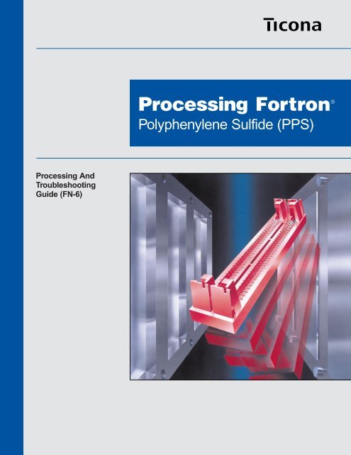
Processing AndTroubleshootingGuide (FN-6)Processing <strong>Fortron</strong> ®Polyphenylene Sulfide (<strong>PPS</strong>)
<strong>Fortron</strong> ® <strong>PPS</strong> Processing and TroubleshootingRecommended Injection Molding Setup ConditionsUnreinforced GradesReinforced Grades0205P4, 0214P2 1130 Series, 1140 Series,4184 Series, 6165 SeriesMelt Temperature*, °F (°C) 560-620 (293-327) 590-640 (310-338)Mold Temperature, °F (°C) 275-325 (135-163) 275-325 (135-163)Injection Pressure, psi (MPa) 2000-6000 (13.8-41.4) 5000-10000 (34.5-69.0)Back Pressure, psi (MPa) 0 (0) 0 (0)Screw Speed, rpm 40-100 40-100Cushion, in. (mm) 1/8-1/4 (3.18-6.35) 1/8-1/4 (3.18-6.35)Drying Conditions 3 hours @ 250°F (121°C) 3-4 hours @ 275°F (135°C)Recommended Extrusion Setup ConditionsUnreinforced GradesReinforced Grades0214 Series, 0300 Series 1140A0Feed Zone Temperature, °F (°C) 545-555 (285-290) 555-575 (290-300)Transition Zone Temperature, °F (°C) 555-565 (290-295) 555-590 (290-310)Metering Zone Temperature, °F °(C) 555-575 (290-300) 570-610 (300-320)Adapter Temperature, °F (°C) 570-590 (300-310) 570-610 (300-320)Die Temperature, °F (°C) 570-590 (300-310) 570-610 (300-320)Melt Temperature, °F (°C) 560-620 (293-327) 580-640 (304-338)Typical Draw-down 2:1 2:1Drying Conditions 3 hours @ 250°F (121°C) 4 hours @ 270°F (132°C)<strong>Fortron</strong> ® <strong>PPS</strong> Processing Benefits• <strong>Hi</strong>gh melt flow, fast cycle grades improve productivity.• New grades can reduce or eliminate deflashing and exhibit lower flash compared to conventional<strong>PPS</strong> resins.• Easily fills long, thin-walled parts.• Processes very well on wide variety of injection molding equipment includinghydraulic and toggle machines.• Grades have low moisture absorption which improves resin transport in the feedsection and reduces “bridging” in the hopper.• Extrusion grades are available for fiber and monofilament production as well as tubing,rod and slab.* Safety Note! Under no circumstances should the melt temperature rise above 698°F (370°C); otherwise polymerdecomposition may result with the production of gases which may be irritating to the eyes and respiratory tract.See <strong>Fortron</strong> ® <strong>PPS</strong> MSDS for further information.
<strong>Fortron</strong> ® <strong>PPS</strong> Processing and TroubleshootingForewordThis revised issue of the <strong>Fortron</strong> ® <strong>PPS</strong> Processing and Troubleshooting Guide (FN-6) is made necessaryby both the advances in processing information and the introduction of new <strong>Fortron</strong> ® <strong>PPS</strong> grades since thefirst edition was published in 1988. It is primarily intended for the processors (both molders and extruders)of high performance thermoplastic products, who require both general and specific information pertainingto processing <strong>Fortron</strong> ® <strong>PPS</strong>. It also contains material of interest to the parts designer, specifier and toolbuilder who wish to obtain a general overview of <strong>PPS</strong> chemistry and technology.The manual deals with four fundamental stages of production: dimensional stability of molded parts,equipment selection, tool design including the hot runner systems used in injection molding, andprocessing parameters. It also includes a troubleshooting guide for solving processing problems whichmay arise during the molding cycle.We hope that this manual helps you, the molder/extruder, process engineer, or tool designer to optimizethe processing cycle of <strong>Fortron</strong> ® <strong>PPS</strong>, and in so doing enable your customers to take full advantage ofthis high performance product. We would welcome your comments and suggestions for improving thismanual in future editions.For more information on the design aspects and material characteristics of <strong>Fortron</strong> ® <strong>PPS</strong>, the readeris encouraged to consult the following manuals: <strong>Design</strong>ing with Plastic: The Fundamentals(TDM-1), <strong>Design</strong>ing with <strong>Fortron</strong> ® <strong>PPS</strong> (FN-10), and <strong>Fortron</strong> ® <strong>PPS</strong> Short Term Properties Guide (FN-4),all of which are available by contacting your local Ticona Sales Office or by calling Technical Informationat 1-800-833-4882.i
<strong>Fortron</strong> ® <strong>PPS</strong> Processing and TroubleshootingTable of ContentsChapter 1. OverviewChemistry of <strong>Fortron</strong> ® <strong>PPS</strong> . . . . . . . . 1-1General Characteristics of <strong>Fortron</strong> ® <strong>PPS</strong> . . . . . . 1-1Reinforcements . . . . . . . . . 1-1Flash . . . . . . . . . . . 1-1Product Support . . . . . . . . . 1-1Agency Approvals . . . . . . . . . 1-1Chapter 2. Dimensional StabilityCoefficient of Linear Thermal Expansion . . . . . . 2-1Shrinkage from Injection Molding . . . . . . . 2-1Warpage . . . . . . . . . . 2-3Annealing . . . . . . . . . . 2-3Tolerances with Injection Molding . . . . . . . 2-5Moisture Absorption . . . . . . . . . 2-5Chapter 3. Equipment Selection and PreprocessingMolding Equipment . . . . . . . . . 3-1Clamping Systems . . . . . . . . 3-1Plasticizing Capacity . . . . . . . . 3-1Screw <strong>Design</strong> . . . . . . . . . 3-2Tool <strong>Design</strong> . . . . . . . . . . 3-2Tool, Screw, and Barrel Materials . . . . . . 3-2Drafts and Undercuts . . . . . . . . 3-2Gate Location . . . . . . . . . 3-2Gate Size . . . . . . . . . . 3-3Gate Geometries . . . . . . . . . 3-3Runner <strong>Design</strong> . . . . . . . . . 3-3Vents . . . . . . . . . . 3-3Mold Heating . . . . . . . . . 3-3Hot Runner Systems . . . . . . . . . 3-3<strong>Design</strong> Recommendations . . . . . . . 3-5Compound Storage . . . . . . . . . 3-5Use of Regrind . . . . . . . . . 3-5Drying Considerations . . . . . . . . . 3-5Drying Equipment . . . . . . . . . 3-5Drying Process . . . . . . . . . 3-6Chapter 4. Processing ParametersInjection Molding . . . . . . . . . 4-1Drying Resin for Injection Molding . . . . . . . 4-1Startup Conditions . . . . . . . . . 4-1Shutdown Conditions . . . . . . . . 4-1Extrusion . . . . . . . . . . . 4-2Drying Resin for Extrusion . . . . . . . 4-2Screw <strong>Design</strong> . . . . . . . . . 4-2Extrusion Parameters . . . . . . . . 4-2Safety and Health Information . . . . . . . . 4-2ii
<strong>Fortron</strong> ® <strong>PPS</strong> Processing and TroubleshootingTable of Contents (Continued)Chapter 5. Troubleshooting GuideOverview of Troubleshooting . . . . . . . . 5-1Burn Marks . . . . . . . . . . 5-1Discoloration . . . . . . . . . . 5-1Dull Surface Appearance . . . . . . . . 5-1Flashing . . . . . . . . . . 5-1Nozzle Problems . . . . . . . . . 5-1Nozzle Drool . . . . . . . . . 5-1Nozzle Freeze-off . . . . . . . . . 5-1Poor Dimensional Control . . . . . . . . 5-2Short Shots, Pit Marks, and Surface Ripples . . . . . 5-2Sinks and Voids . . . . . . . . . 5-2Sticking Problems . . . . . . . . . 5-2Sticking in the Cavity . . . . . . . . 5-2Sticking on the Core . . . . . . . . 5-2Sticking in the Sprue Bushing . . . . . . . 5-3Unmelted Pellets . . . . . . . . . 5-3Warpage and Part Distortion . . . . . . . . 5-3Weld Lines . . . . . . . . . . 5-3Runnerless Mold Troubleshooting . . . . . . . 5-4List of Figures and TablesFigure 1.1 Idealized <strong>PPS</strong> Structure . . . . . . . 1-1Figure 2.1 Dimensional Change of 65% Min./Glass <strong>PPS</strong> . . . . 2-1Figure 2.2 Dimensional Change of 40% Min./Glass <strong>PPS</strong> . . . . 2-1Figure 2.3 Effect of Part Thickness on Shrinkage . . . . . 2-2Figure 2.4 Effect of Filler Level on Shrinkage . . . . . . 2-2Figure 2.5 Effect of Injection Pressure on Shrinkage (40% Min./Glass) . . 2-2Figure 2.6 Effect of Injection Pressure on Shrinkage (65% Min./Glass) . . 2-2Figure 2.7 Specifications for Warpage Sample . . . . . 2-3Figure 2.8 Measured Points for Warpage Sample . . . . . 2-4Figure 2.9 Warpage with Respect to Flatness . . . . . . 2-4Figure 2.10 Warpage with Respect to Cylinder Roundness . . . . 2-4Figure 2.11 Warpage with Respect to Hole Roundness . . . . 2-4Figure 2.12 Warpage with Respect to Bowing Angle . . . . . 2-4Figure 2.13 Moisture Absorption of Plastics . . . . . . 2-6Figure 3.1 Schematic of Single-Stage Injection Molding Machine . . . 3-1Figure 3.2 Schematic of Metering Screw Recommended for <strong>Fortron</strong> ® <strong>PPS</strong> . . 3-2Figure 3.3 Specifications for a Submarine Gate . . . . . 3-3Figure 3.4 Drawing and Schematic of a Hot Runner System . . . . 3-4Figure 3.5 Hopper Dryer Unit . . . . . . . . 3-6Figure 4.1 Effect of Mold Temperature on Heat Deflection Temperature . . 4-1Table 1. Long Term Dimensional Reproducibility of <strong>Fortron</strong> ® <strong>PPS</strong> . . 2-5Table 2. Property Retention after Five Molding Cycles . . . . 3-5Table 3. Injection Molding Conditions for <strong>Fortron</strong> ® <strong>PPS</strong> . . . . 4-1Table 4. Extrusion Conditions for <strong>Fortron</strong> ® <strong>PPS</strong> . . . . 4-2Table 5. Typical Extruder Screw Dimensions . . . . . 4-2iii
<strong>Fortron</strong> ® <strong>PPS</strong> Processing and Troubleshootingiv
<strong>Fortron</strong> ® <strong>PPS</strong> Processing and TroubleshootingChapter 1<strong>Fortron</strong> ® <strong>PPS</strong> OverviewChemistry of <strong>Fortron</strong> ® <strong>PPS</strong><strong>Fortron</strong> ® <strong>PPS</strong> products are based on an aromaticlinear poly(phenylene sulfide) (<strong>PPS</strong>) polymer producedby a polycondensation reaction. The polymer has thefollowing structure:Figure 1.1 Idealized <strong>PPS</strong> StructureSnGeneral Characteristics of <strong>Fortron</strong> ® <strong>PPS</strong>The structure of <strong>Fortron</strong> ® <strong>PPS</strong> polymer contributes tothe following desirable properties:• <strong>Hi</strong>gh thermal stability.• Excellent chemical resistance.• Inherent flame resistance without theaddition of flame retardants.• Excellent electrical properties.• Excellent flow.<strong>Fortron</strong> ® <strong>PPS</strong> is further distinguished from highlybranched <strong>PPS</strong> products by the following performanceadvantages:• Faster cycle times and possible eliminationof the deflashing operation.• <strong>Hi</strong>gher elongation and impact strength.• Improved viscosity consistency.• <strong>Hi</strong>gher weld line strength.• A natural light beige color for the<strong>Fortron</strong> ® <strong>PPS</strong> base resin for easiercoloring.Reinforcements and Fillers<strong>Fortron</strong> ® <strong>PPS</strong> resin is available in a range of basepolymer, glass-reinforced, and mineral/glass-reinforcedsystems for injection molding, extrusion blowmolding, and extrusion. Selection of the appropriategrade of <strong>Fortron</strong> ® <strong>PPS</strong> and the use of proper processingconditions will aid in minimizing problems such asincomplete filling, flash, warpage, and part distortion.When fillers, such as glass fibers, minerals, or mixturesof these are added to the base resin, the heat distortiontemperature (HDT), is also raised. The HDT ofunreinforced <strong>Fortron</strong> ® <strong>PPS</strong> is about 221°F (105°C) at264 psi, while that of a reinforced <strong>Fortron</strong> ® <strong>PPS</strong> is500+°F (260+°C). Because of this added value and<strong>Fortron</strong> ® <strong>PPS</strong>’s affinity for fillers, the majority of <strong>PPS</strong>applications use glass-reinforced or mineral/glassfilledsystems.Product SupportExperienced field engineers and design engineers areavailable to assist you with product design, materialspecification, and molding trials. For further informationor assistance, please contact your representativefrom Ticona.Agency Approvals<strong>Fortron</strong> ® <strong>PPS</strong> has been granted ratings byUnderwriters Laboratories of UL94 V-0 to 0.031 in.(0.79 mm) thickness and UL94 5VA at 0.0625 in. (1.59mm) on many filled grades, as well as ratings of A00and V0 by the CSA (Canadian Standards Agency).UL yellow cards are available upon request. Some<strong>Fortron</strong> ® <strong>PPS</strong> grades have also been approved underMilitary Specifications M-24519 and M-46174 (ASTMD4067). Consult your Ticona representative for ratingson specific grades of <strong>Fortron</strong> ® <strong>PPS</strong> resin.Most designers choose <strong>Fortron</strong> ® <strong>PPS</strong> because itdemonstrates a valuable combination of propertiesrelative to the load-bearing capabilities anddimensional stability when exposed to chemicalsand high-temperature environments.1-1
<strong>Fortron</strong> ® <strong>PPS</strong> Processing and Troubleshooting1-2
<strong>Fortron</strong> ® <strong>PPS</strong> Processing and TroubleshootingChapter 2Dimensional StabilityIt is important for the part designer to understand theexceptional dimensional control obtainable with<strong>Fortron</strong> ® <strong>PPS</strong>. In the following discussion, the effectsof part tolerance as well as the dimensional effectscaused by shrinkage, annealing, and moisture absorptionwill be considered. Dimensional effects causedby exposure to various chemicals are covered in<strong>Design</strong>ing with <strong>Fortron</strong> ® <strong>PPS</strong> (FN-10).Coefficient of Linear Thermal ExpansionThe coefficient of linear thermal expansion is theslope of the curve divided by the specimen length,i.e., ∆ dimension/(∆ temperature X length). Figures 2.1and 2.2 show the dimensional change for both theflow and transverse directions of 65% mineral/glassreinforcedand 40% glass-reinforced <strong>Fortron</strong> ® <strong>PPS</strong>,respectively. The curves were measured by thePerkin-Elmer Thermomechanical Analyzer (TMA 7)from -13 to 392°F (-25 to 200°C), ASTM TestMethod E831.At the glass transition temperature, T g , the rate ofexpansion changes. Above the glass transitiontemperature, the rate of thermal expansion may shiftdue to an increase in molecular chain motion and itsattendant effects, stress relaxation and/or crystallization.Thus, samples molded from different sourcesand under different conditions will probably yieldresults significantly influenced by the processing andend-use thermal history. This is especially true of datataken in the transverse direction, where the effects oforientation and processing are most pronounced.Shrinkage from Injection MoldingTypically, the mold shrinkage of <strong>Fortron</strong> ® <strong>PPS</strong>products is very low, and therefore, quite suitablefor precision molding. Typical shrinkage values for<strong>Fortron</strong> ® <strong>PPS</strong> products are as follows:40% Glass-Reinforced:• Flow Direction: 0.002-0.006 in./in.• Transverse Direction: 0.004-0.006 in./in.65% Mineral/Glass-Reinforced:• Flow Direction: 0.002-0.006 in./in.• Transverse Direction: 0.003-0.007 in./in.While the shrinkages given above are typical, thesevalues vary, depending on the variables listed onp. 2-3 under Warpage. It is highly recommended thatprototyping be employed prior to cutting a tool todetermine the proper shrinkage for a given part. Ifprototyping is not economical, then for safety it isrecommended that oversized cores and undersizedcavities be cut, since it is always easier and lessexpensive to cut steel than to add it.Expansion (in.).Expansion (in.).0.0050.0040.0030.0020.001Conditions:Length = 0.250 in. (flow)0.255 in. (transverse)Scan Rate = 10.00°C/minLoad = 0.000 gTransverseFlow0-33 -3 27 57 87 117 147 177 207 237 267Temperature (°C)Figure 2.1 Dimensional change of 65% min/glass-reinforced<strong>Fortron</strong> ® <strong>PPS</strong>0.0020.00150.0010.0005Conditions:Length = 0.250 in. (flow)0.255 in. (transverse)Scan Rate = 10.00°C/minLoad = 0.000 gTransverseFlow0-25 0 25 50 75 100 125 150 175 200Temperature (°C)Figure 2.2 Dimensional change of 40% glass-reinforced<strong>Fortron</strong> ® <strong>PPS</strong>2-1
<strong>Fortron</strong> ® <strong>PPS</strong> Processing and TroubleshootingThe effect of part thickness on shrinkage of 40%glass-reinforced and 65% mineral/glass-reinforced<strong>Fortron</strong> ® <strong>PPS</strong> is shown in Figure 2.3. The reason forgreater shrinkage in thicker parts is that thicker partsexhibit slower cooling, which results in a greaterdegree of crystallization, thus causing more shrinkage.Figure 2.4 illustrates the effect of filler/reinforcementlevel on shrinkage of <strong>Fortron</strong> ® <strong>PPS</strong>: as filler levelincreases, shrinkage decreases and becomes lesssensitive to part thickness.Figures 2.5 and 2.6 show the effect of injectionpressure on the shrinkage of 40% glass-reinforcedand 65% mineral/glass-reinforced <strong>Fortron</strong> ® <strong>PPS</strong>,respectively. As injection pressure is increased, theparts are more densely packed, thus slightly decreasingshrinkage. The test piece was 80 X 80 mm, 2 mmthick, with a rectangular (4 X 2 mm) side gate at onepoint; the cylinder temperature was 608°F (320°C),and the mold temperature was 320°F (150°C).0.0101.0Shrinkage (in./in.)0.0080.0060.0040.002Transverse40% Glass-Reinforced65% Mineral-Glass ReinforcedMold Shrinkage (%)0.80.60.40.2TransverseFlowFlow0.0000.04 0.06 0.08 0.1 0.12 0.14Thickness (in.)Figure 2.3 Effect of part thickness on shrinkage of<strong>Fortron</strong> ® <strong>PPS</strong>06 7 89 10 11Injection Pressure (kpsi)Figure 2.5 Effect of injection pressure on shrinkage of<strong>Fortron</strong> ® <strong>PPS</strong> (40% glass)0.0121.00.0101/8 in. thick plaque1/16 in. thick plaque0.8Shrinkage (in./in.)0.0080.0060.004Mold Shrinkage (%)0.60.4Transverse0.0020.2Flow0.00030 35 40 45 50 55 60 65 70 75Reinforcement (%)Figure 2.4 Effect of filler level on shrinkage of <strong>Fortron</strong> ®<strong>PPS</strong> (Please note that not all reinforcementlevels are available as commercial products.)06 7 89 10 11Injection Pressure (kpsi)Figure 2.6 Effect of injection pressure on shrinkage of<strong>Fortron</strong> ® <strong>PPS</strong> (65% mineral/glass)2-2
<strong>Fortron</strong> ® <strong>PPS</strong> Processing and TroubleshootingWarpageAnisotropic effects on dimensions (warping) can becaused by a number of factors, including thefollowing:• Mold temperature.• Nonuniform part thickness.• Nonuniform cooling.• Filler type/level.• Orientation of filler.• Location of dimensions with respectto the gate.• Molded-in stresses.• Gate size.To describe the effects of anisotropy in geometricallycomplex parts, a sample part containing a variety ofshapes was designed. Figure 2.7 shows the specificationsfor this warpage sample. Figure 2.8 shows themeasured points used to obtain the data shown inFigures 2.9 - 2.12, which compare the largest dimensionaldifferences of 40% glass-reinforced and 65%mineral/glass-reinforced <strong>Fortron</strong> ® <strong>PPS</strong> products withrespect to flatness (Figure 2.9), roundness of acylinder (Figure 2.10), roundness of a hole (Figure2.11), and bowing angle (Figure 2.12).From these figures it can be seen that 65% mineral/glass-reinforced <strong>Fortron</strong> ® <strong>PPS</strong> has the least warpage,due to the fact that this material uses less glass thanthe 40% glass-reinforced material, and that mineralfiller has a smaller aspect ratio than glass fibers.AnnealingWhen processed at a mold temperature of275°F (130°C) or greater, parts molded of <strong>Fortron</strong> ®<strong>PPS</strong> are able to fully crystallize, and therefore, showvery little continued shrinkage when exposed totemperatures as high as 450°F (232°C) for 24 hr.A study of the effects of annealing <strong>Fortron</strong> ® <strong>PPS</strong> productsshowed the following additional shrinkage valuesfor the flow direction, using 1/8-in. thick samples:40% Glass-Reinforced:• 0.0009 in./in. after 2 hr. annealing.• 0.001 in./in. after 24 hr. annealing.65% Mineral/Glass-Reinforced:• 0.001 in./in. after 2 hr. annealing.• 0.0012 in./in. after 24 hr. annealing.Thus, there is very little advantage in annealing asample molded at or above 275°F (130°C) for morethan 2 hr. to obtain further shrinkage.<strong>Fortron</strong> ® <strong>PPS</strong> can be molded at lower mold temperaturesat the expense of reduced thermal/load properties,i.e., heat distortion temperature. Annealing partsthat have been molded at lower temperatures lessthan 275°F (130°C) will increase the load-bearingcapabilities of those parts, but such practice maycause warpage; thus, strict care (e.g., fixturing thepart) should be taken with parts requiring criticaltolerances.1450801002017201.523192Figure 2.7 Specifications for warpage sample, dimensions in millimeters2-3
<strong>Fortron</strong> ® <strong>PPS</strong> Processing and TroubleshootingFlatnessRoundness of a CylinderB-B´A-A´310Bowing Angle θ Roundness of a HoleFigure 2.8 Measured points for warpage sampleFigure 2.8 Top view83Variation inFlatness (mil)642Variation inRoundness (mil)21040% Glass 65% Min/GlassMaterial TypeFigure 2.9 Warpage with respect to flatness4040% Glass 65% Min/GlassMaterial TypeFigure 2.11 Warpage with respect to roundness of a hole2Variation inRoundness (mil)321A-A´ LowerB-B´ UpperVariation in BowingAngle (degree)1.510.5040% Glass 65% Min/GlassMaterial TypeFigure 2.10 Warpage with respect to roundness of a cylinder040% Glass 65% Min/GlassMaterial TypeFigure 2.12 Warpage with respect to bowing angle2-4
<strong>Fortron</strong> ® <strong>PPS</strong> Processing and TroubleshootingTolerances with Injection MoldingWhen <strong>Fortron</strong> ® <strong>PPS</strong> is injection molded, it is possibleto routinely hold tolerances of 2-3 mil/in. To achievetolerances such as 1 mil/in., the material should beuniformly oriented in the direction of flow, and precisionprocessing machinery, including at least thefollowing parameters, should be used:• Uniform tool heating (efficient oil flow andproper placement of cooling lines).• Closed-loop, feedback controllers fortemperatures, pressures, injection speeds,and ram distances.<strong>Fortron</strong> ® <strong>PPS</strong> for 10 months. At the end of 10 months,the variability over a 1.9593 in. dimension was ±0.0006 in. (0.03%).Moisture Absorption<strong>Fortron</strong> ® <strong>PPS</strong> products are not hygroscopic, andtherefore, do not experience dimensional expansionlike polyamides. For both 40% glass-reinforced and65% mineral/glass-reinforced <strong>Fortron</strong> ® <strong>PPS</strong> products,a typical moisture absorption value is 0.03%, testedaccording to ASTM Method D-570 by immersion inwater at 73°F (23°C) for 24 hr. Figure 2.13 shows howthis value compares with those of other engineeringplastics under the same conditions.Table 1 demonstrates the dimensional reproducibilityobtained in molding 65% mineral/glass-reinforcedTable 1. Long-term dimensional reproducibility of injection molded <strong>Fortron</strong> ® <strong>PPS</strong>3σ/x––Reproducibility–x σ 3σ/x––X 100 (%) forTest Date (in.) (in.) X 100 (%) for 3 days 10 months8/10/88 1.9593 0.00016 0.0248/11/88 1.9593 0.00012 0.017 0.0228/12/88 1.9594 0.00016 0.02511/17/88 1.9594 0.00016 0.02611/18/88 1.9593 0.00016 0.025 0.02511/19/88 1.9592 0.00016 0.0252/27/89 1.9592 0.00024 0.0362/28/89 1.9591 0.00028 0.043 0.0352/29/89 1.9592 0.00016 0.026Dimension =1.9593 in.± 0.0006 in.(0.030%)5/29/89 1.9593 0.00020 0.0295/30/89 1.9593 0.00016 0.022 0.0275/31/89 1.9594 0.00020 0.0292-5
<strong>Fortron</strong> ® <strong>PPS</strong> Processing and Troubleshooting0.250.2LongGlassWater Absorption (%)0.150.1ShortGlass67%Glass30%Glass33%Glass0.050Phenolics40%Glass65%Min/Glass45%Min/GlassVinyl Ester SMC <strong>PPS</strong> PET PPAMaterial TypeFigure 2.13 Comparison of the moisture absorption of several plastics by immersion in water at 73°F (23°C) for 24 hr2-6
<strong>Fortron</strong> ® <strong>PPS</strong> Processing and TroubleshootingChapter 3Equipment Selection and PreprocessingSelection of the appropriate equipment for an applicationand the proper drying of the resin can be importantfactors in producing quality molded parts. Thischapter explains how to deal with these considerationswhen preparing to process <strong>Fortron</strong> ® <strong>PPS</strong>.Molding EquipmentBecause the molding process is so crucial to theproduction of high-quality parts, a good understandingof both the molding equipment and the moldingprocess is essential. Figure 3.1 shows a cut-awaydiagram of a single-stage, reciprocating screw injectionmolding machine, listing its basic parts.Clamping SystemsWithin the molding machine, the clamp force (to keepthe mold closed) is developed either by a togglemechanism or by a hydraulic cylinder. With <strong>Fortron</strong> ®<strong>PPS</strong>, the clamp force for a typical molding machineshould be between 3 and 5 tons of force per squareinch of projected area (including the runner).The advantages of a toggle clamping system are thatit provides a faster mold opening and closing and isless expensive than a hydraulic system. However,there are more parts to wear out in a toggle systemthan in a hydraulic system.The advantages of a hydraulic system are that itallows a faster mold setup and the exact clamppressure can be read to determine its adequacy.However, because a hydraulic system uses oil to drivethe clamp, a hydraulic system is more prone to oilleaks than is a toggle system.A hydromechanical system uses both hydraulic andtoggle systems together, thus combining some of theadvantages of both the toggle (high-speed close andopen) and hydraulic (precise control of clamp tonnage)systems. In such a system, a piston or othersimilar device provides fast initial closing, while ahydraulic system is used in the final clamp stroke.Thus, the danger of overtoggling is eliminated by theprecision of the hydraulic phase.Plasticizing CapacityAs with other engineering thermoplastics, <strong>Fortron</strong> ®<strong>PPS</strong> grades should not be exposed to excessivetemperatures during processing. The smallest shotsize should be selected which allows both adequatepart fill and a consistent cushion, A shot weight of 50-70% of the machine’s capacity is optimum. Studieshave shown that barrel residence times in excess often minutes may result in a modest decrease inviscosity and color darkening. Mechanical properties,however, are virtually unchanged.Injection CylinderHeater BandsFeed HopperNozzleNonreturn Flow Valve Assembly Rotating and Reciprocating Screw Screw-Piston ShaftFigure 3.1 Single-stage reciprocating screw injection molding machine3-1
<strong>Fortron</strong> ® <strong>PPS</strong> Processing and TroubleshootingOverall LengthShankLengthFeedDepthOutsideDiameterFlight LengthMeteringDepthValveFeedZone1/3TransitionZone1/3MeteringZone1/3Figure 3.2 Metering type screw recommended for Ticona <strong>Fortron</strong> ® <strong>PPS</strong> resins (for terminology only)Screw <strong>Design</strong>Figure 3.2 shows a typical metering type screwrecommended for Ticona <strong>Fortron</strong> ® <strong>PPS</strong> resins. Thefigure shows the three major sections of the screw:the feed section, the transition section, and the meteringsection. As seen in the diagram, the feed sectionand metering section both contain a constant rootdiameter, while the transition section contains aninvoluted taper. Proper screw design for <strong>Fortron</strong> ® <strong>PPS</strong>resins follows these general guidelines:• Zone distribution = 1/3 feed zone, 1/3transition zone, and 1/3 metering zone.• L/D ratio = 16:1 to 24:1.• Compression ratio = 3:1 to 4:1• Check ring strongly recommended.Improper combinations of screw and barrel materialscan lead to premature wear. It is highly recommendedthat suppliers of these products be consulted.Construction materials are continuously changing andimproving. As a result, new products may be availableto improve wear resistance.Tool <strong>Design</strong>Tool, Screw, and Barrel MaterialsAs with all filled plastic products, proper materialsmust be used in the construction of molds, screws,and barrel liners because glass and mineral fillermaterials are abrasive. This is also true of <strong>Fortron</strong> ®<strong>PPS</strong> products.The abrasive nature of glass and minerals also affectsthe screws and barrels. The proper materials forconstruction are important to ensure long life. Stellite ®alloy is recommended for screws, and Xaloy ® 800alloy is recommended for barrel liners for long barrellife. It is important that compatible materials for screwand barrel are utilized. Newer type alloys usingvanadium have been extremely successful forprocessing requiring minimum wear.For high-volume production parts, the recommendedsteels for cores and cavities should have good wearresistance properties. The tool steels should have ahardness Rc>50. An SPI/SPE A2 class finish hasbeen successfully used. For tools that are especiallydifficult to vent adequately, corrosion-resistant steelsare recommended.Drafts and UndercutsSignificant undercuts should be avoided and draftangles of 1/2 to 1° should be incorporated into a wellpolished mold. In order to obtain strong, stiff dimensionallystable parts, it is necessary to allow <strong>Fortron</strong> ® <strong>PPS</strong> tofully crystallize in the mold. The above recommendationsabout drafts and undercuts should be followed toavoid problems in removing parts from the mold.Gate LocationGates should be located to provide a flow that isuniform and uninterrupted. Generally, the number ofgates should be kept to a minimum. It is commonpractice to use multiple gates when dealing with along flow length and/or thin-wall parts to reduce thepressure, and therefore minimize flash. When multiplegates are necessary, they should be placed so thatthe weld lines in the product are formed in areas withminimal load-bearing requirements. Where possible,adjacent flow fronts should be forced to meet at anacute angle so that a meld line is formed. Venting atthe weld line also promotes stronger welds.3-2
<strong>Fortron</strong> ® <strong>PPS</strong> Processing and TroubleshootingGate SizeThe size of the gate is related to the nominal wallthickness. Rectangular gates should always be atleast as wide as they are deep.The high flow of <strong>Fortron</strong> ® <strong>PPS</strong> materials permits theuse of very small gates (as low as 0.04 in. diameter).For example, submarine or pinpoint gates typicallyhave a 0.040-0.070 in. diameter. <strong>Hi</strong>ghly filled mineral/glass products may require larger gates. This smallergate area minimizes gate vestige and providessatisfactory part separation from the runner. For edgegates, a typical starting point is 50% of the nominalwall thickness. Typical land length is 0.020 in.Gate GeometriesAny kind of gate may be used for molding <strong>Fortron</strong> ®<strong>PPS</strong>. For a review of the various types of gates, seeFigure 2 in <strong>Design</strong>ing with Plastic: The Fundamentals.(Bulletin TDM-1). If a submarine gate is selected, itshould conform approximately to the geometryrecommended in Figure 3.3.Runner <strong>Design</strong>Full-round runners with a diameter as small as 0.125in. (6 mm) are used for molding <strong>Fortron</strong> ® <strong>PPS</strong>.Equivalent trapezoidal runners may also be used.When a multicavity mold is used, the runner systemshould be balanced to ensure that all cavities finishfilling simultaneously. This balance prevents any onecavity from being overpacked.Cut runner as closeas possible to partParting Line60°VentsVents should be located in all sections of the moldcavity where air may become trapped by the molten<strong>Fortron</strong> ® <strong>PPS</strong>, particularly in the last areas to fill. Thetendency of <strong>PPS</strong> to flash dictates that shallow vents,ca. 0.0005 in. deep by 0.25 in. wide (0.012 mm by6.350 mm), be used. In areas where flash is not aconcern, vents as deep as 0.001 in. (0.025 mm) maybe employed. Inadequate venting traps gas, causingincomplete filling of the part, burn marks, molddeposit, corrosion, and/or poor weld line strength. Thevent land length should be about 1/16 in. (1.588 mm)and then widened to the edge of the tool.Mold HeatingWhen molding <strong>Fortron</strong> ® <strong>PPS</strong>, oil circulating heaters orelectric cartridge heaters should be used to allow themold temperature to reach the recommended rangeof 275-325°F (135-165°C). The oil channels, andcartridge heaters should be placed about one channel/heaterdiameter from the surface of the moldcavity and 3-5 diameters apart. Enough channels/heaters should be used to ensure that the mold cavityreaches a uniform temperature. Insulation for themold can also be used to reduced heat loss andenergy requirements.Hot Runner SystemsBecause the costs of labor and materials have continuedto increase, efforts to lower the costs of processingand to produce higher quality moldings at lowercosts have also increased. These efforts havesparked new interest in automation, including the useof runnerless molds. The increased interest inrunnerless molds has produced a rapid expansion inthis technology and a proliferation of commerciallyavailable runnerless molds.Part0.040-0.060 in. diameter(1.00-1.50 mm)The objective of a hot runner system is to reducematerial and labor costs and to increase productivityby accelerating molding cycles and by reducingscrap.The parts of a hot runner system are shown inFigure 3.4.20°Figure 3.3 Specifications for a submarine gateRunnerless components/systems are commerciallyavailable from suppliers such as D-M-E Co., Ewikon,Husky, Incoe Corp., Kona, Mold Masters Ltd., andSpear Systems.3-3
<strong>Fortron</strong> ® <strong>PPS</strong> Processing and Troubleshooting(A)Cylinder AssemblyExtension NozzleManifoldBushingBand HeaterMelt FlowChannelGatePin GuideValve Pin(B)Spiral HeaterFigure 3.4 Drawing (A) and labeled schematic (B) of a hot runner systemTo successfully use <strong>Fortron</strong> ® <strong>PPS</strong> in a hot runnersystem, the components making up that system mustbe properly selected and optimized. These componentsinclude the manifolds, bushings or probes, gatetypes, and controllers. Before a runner system can bedesigned, the manufacturer/supplier of the runnersystem must know whether the material is to be neator filled, the shear rate of the material, the flow length ofthe material, the wall thickness and weight of the part,and other characteristics of the plastic. This sectiongives some general guidelines for using <strong>Fortron</strong> ® <strong>PPS</strong>in a hot runner system. It is imperative that the manufacturerof the system be involved at the concept stageof mold design for success. Most suppliers provideguidelines for such work, while others provide completedesign services.3-4
<strong>Fortron</strong> ® <strong>PPS</strong> Processing and Troubleshooting<strong>Design</strong> RecommendationsFollowing are recommendations for designing arunnerless mold for use with <strong>Fortron</strong> ® <strong>PPS</strong>:• Valve gates are recommended to reducedrool.• It is important to design a system that can beopened easily for cleaning or maintenance.• Before designing the mold, inform the moldmaker whether the material has a filler. Thisallows the mold maker to specify the correcttool steel and hardness of steel. For molding<strong>Fortron</strong> ® <strong>PPS</strong>, A2, or other similar steels arerecommended to lessen the effects of wear.• Because <strong>Fortron</strong> ® <strong>PPS</strong> has such excellentflowability, it will flow into any dead spots orcrevices in the runner system, and eventuallydegrade there. Take care to design smoothsurfaces. Dead spots are also detrimentalwhen processing colors. Smooth surfacesand the absence of dead spots also improveefficient purging.• Externally heated runner systems arerecommended.• Regarding temperature, the manifold anddrops should be viewed as an extension ofthe barrel. Temperatures should be the sameas that of the melt in the barrel—the manifoldtemperature should neither heat nor coolthe plastic.Temperature control is most important. Typicalvariations in the melt temperature of <strong>Fortron</strong> ® <strong>PPS</strong> donot adversely affect the mechanical properties, nordoes the material exhibit burning. However, temperaturemust still be controlled because temperature andfluctuations in temperature may affect the viscosity orfilling of <strong>Fortron</strong> ® <strong>PPS</strong> in the mold. The viscosity of thematerial slightly decreases with higher temperaturesfor prolonged periods (up to 15 min).Variations in temperature can be also caused byvariations in the power to the unit. Such variations canbe caused by the starting and stopping of motors orother high-current devices, peak loads of communities(particularly on the hot days of summer), etc. Aclosed-loop temperature control can effectivelymanage such variations, and is highly recommended.Finally, the safety aspects of controlling the temperatureshould not be overlooked. The melt processingtemperature for <strong>Fortron</strong> ® <strong>PPS</strong> should never exceed698°F (370°C).Compound StorageDuring storage of engineering plastics, it is importantto keep all materials as warm and as dry as possible.Cold temperatures bring the danger of moisturecondensation on the surface of the compound, whilesummer poses the problem of surface moistureadsorption due to high humidity. Moisture from allsources must be eliminated by drying.Use of RegrindFor cost effectiveness, dried regrind resin may beused. However, no more than a 25% concentration isrecommended at this time. Too high a percentage ofregrind may result in reduced mechanical properties,particularly in glass-reinforced grades because thelength of the glass fibers is reduced. Regrind shouldbe as free of dust as possible. It is important thatrunners, sprues, and rejects be ground and mixed wellwith virgin pellets. After mixing, the mixture of regrindand virgin pellets should be treated with the samecare as virgin pellets, including keeping the mixturefree of contamination and moisture just as meticulouslyas with virgin resin. Table 2 below shows the excellentmechanical property retention for two <strong>Fortron</strong> ® gradesafter multiple (5) molding cycles using 100 % regrind.Table 2. Property Retention after Five Molding CyclesProperty ASTM Initial 40% Glass- 65%Method Value Reinforced Mineral/after 5th Glass-Molding Reinforcedafter 5thMoldingTensile Strength D638 100% 81% 79%Elongation D638 100% 82% 83%Flexural Strength D790 100% 88% 82%Flexural Modulus D790 100% 84% 95%3-5
<strong>Fortron</strong> ® <strong>PPS</strong> Processing and TroubleshootingDrying Considerations<strong>Fortron</strong> ® <strong>PPS</strong> is not hygroscopic, yet it is important touse dry resin in molding parts. <strong>Hi</strong>gh moisture levelscan create voids, which could adversely impact partperformance or affect aesthetics.Drying Equipment<strong>Fortron</strong> ® <strong>PPS</strong> should be dried in dehumidifying hopperdryers, such as the one shown in Figure 3.5. It shouldbe noted that hot-air ovens are not recommended,although they may be used if extreme care is taken.The reasons such ovens are not recommended are: a)if the trays are filled too high (more than 1-1.5 in.), thematerial on the bottom of the tray is not properly dried;b) if several different kinds of materials are being driedin the oven (on different trays) at the same time, pelletscan easily fall onto a lower tray, causing contaminationof the material on the lower tray.Drying ProcessIn Figure 3.5, a vacuum loader (1) drops resin into theinsulated drying hopper on demand. Heated, dehumidifiedair enters the drying hopper (2), penetratingthe resin and carrying moisture vapor up to the returnline outlet. The moisture-laden air passes through a filter(3) to remove very small particles before the airreenters the desiccant cartridge. This filter must bekept clean! Dirty, plugged filters restrict air flow andreduce drying efficiency. The process air blower (4)forces moisture-laden air through onstream desiccantcartridges (5), where moisture is trapped. The dehumidifiedair is then reheated (6) and delivered back tothe drying hopper. While the desiccant cartridge is onstream, removing moisture, another cartridge is beingregenerated. Separate regeneration blowers (7) andheaters (8) are used for that purpose.1. Vacuum Loader2. Drying Hopper3. Filter4. ProcessAir Blower5. DesiccantCartridge6. DehumidifiedAir Reheater7. RegenerationBlower8. RegenerationHeaterFigure 3.5 Hopper dryer unit (Reprinted with permission of Novatec , Inc., Baltimore, MD)3-6
<strong>Fortron</strong> ® <strong>PPS</strong> Processing and TroubleshootingChapter 4Processing ParametersCareful control of processing plays a crucial role inproducing high-quality plastic parts. It is advantageousfor all concerned to be fully aware of the optimumprocessing parameters, since only in this way can oneachieve the full capabilities of <strong>Fortron</strong> ® <strong>PPS</strong> resin.Injection Molding<strong>Fortron</strong> ® <strong>PPS</strong> injection-molded parts exhibit adesirable combination of high-temperature mechanicalproperties, low creep, superior chemical resistance,and excellent electrical properties. All grades can beprocessed easily.Recommended Drying ConditionsAlthough <strong>Fortron</strong> ® <strong>PPS</strong> resins do not absorb a highpercentage of atmospheric moisture, exposure toambient air should be kept to a minimum. Both virginand regrind <strong>Fortron</strong> ® <strong>PPS</strong> resin of all grades should bedried for 3-4 hours at 275°F (135°C) for filled gradesand 3 hours at 250°F (121°C) for unfilled grades withthe dryer dew point setting of about -20°C.Injection Molding ConditionsStartup ConditionsTable 3 shows the recommended molding conditionsfor <strong>Fortron</strong> ® <strong>PPS</strong> resin. The operator should allow themachine to stabilize for half an hour at the recommendedzone temperatures before rotating the screw.Upon startup, the molding machine should be purgedwith high-density polyethylene or polypropylene at thetemperatures recommended for molding <strong>Fortron</strong> ® <strong>PPS</strong>.Once the machine has been purged, <strong>Fortron</strong> ® <strong>PPS</strong>may be fed into the machine and purged until only<strong>Fortron</strong> ® <strong>PPS</strong> is present in the barrel. The melt temperatureshould then be checked with a pyrometer toensure that the melt is within the recommendedtemperature range.The most critical practice in molding <strong>Fortron</strong> ® <strong>PPS</strong>resin is the use of a hot mold, i.e., a minimum moldtemperature of 275°F (135°C). This temperature isrequired to allow full crystallization of the resin and toachieve the necessary resistance to heat distortion ofthe part being molded (see Figure 4.1).Shutdown ConditionsWhen a machine is being shut down from molding<strong>Fortron</strong> ® <strong>PPS</strong> resin, the nozzle and barrel heatersshould be maintained at the molding temperature.The machine should be first purged with high-densitypolyethylene or polypropylene. When the barrel iscompletely purged of <strong>Fortron</strong> ® <strong>PPS</strong> resin and is filledwith polypropylene or high-density polyethylene, themachine may be shut down. Leave the ram in theforward position when the machine is shut down.Table 3. Injection Molding Conditions for <strong>Fortron</strong> ® <strong>PPS</strong>Molding ParametersCylinder TemperaturesMolding Values°F (°C)Feed Zone 585-635 (307-335)Intermediate Zone 590-640 (310-338)Front Zone 600-640 (315-338)Nozzle Temperature 600-640 (315-338)Melt Temperature* 590-640 (310-338)Mold Temperature 275-325 (135-163)Injection Pressure, psi 5,000-15,000 (34-104)(MPa)Injection SpeedBack Pressure, psiMedium to FastNoneScrew Speed, rpm 40-100Cushion, in. (mm) 1/8-1/4 (3-6)*Safety Note! Under no circumstances should the melttemperature rise above 698°F (370°C); otherwisepolymer decomposition may result with the productionof gases which may be irritating to the eyes andrespiratory tract. See <strong>Fortron</strong> ® <strong>PPS</strong> MSDS for furtherinformation.HDT @264 psi (°F)60050040030020010050100150200250300Mold Temperature (°F)350400Figure 4.1 Effect of mold temperature on heat deflectiontemperature.4-1
<strong>Fortron</strong> ® <strong>PPS</strong> Processing and TroubleshootingExtrusion Parameters<strong>Fortron</strong> ® <strong>PPS</strong> has been successfully extruded intovarious shapes and sizes including:• Monofilament• Rods• Slabs• TubingExtrusion GuidelinesThe following guidelines are for establishing conditionsfor extruding <strong>Fortron</strong> ® <strong>PPS</strong>. Careful control of temperaturesand proper screw design is necessary foroptimum productivity.Table 4. Extrusion Conditions for <strong>Fortron</strong> ® <strong>PPS</strong>ExtrusionParametersFeed ZoneUnfilled545-555°F(285-290°C)Filled555-575°F290-300°C)Transition 555-565°F 555-590°FZone (290-295°C) (290-310°C)Metering 555-575°F 570-610°FZone (290-300°C) (300-320°C)AdapterDie570-590°F(300-310°C)570-590°F(300-310°C)570-610°F(300-320°C)570-610°F(300-320°C)and low melt temperature and pressure variations. Thescrew L/D ratio may range from 16:1 to 24:1. As withinjection molding, the zone distribution should beequal: 1/3 metering zone, 1/3 transition zone, and 1/3feed zone. Table 5 shows the proper flight depths forseveral typical sizes of extruders.Table 5. Typical extruder screw dimensionsExtruder Size Metering Depth Feed Depthinches (mm) inches (mm) inches (mm)1.5 (35) 0.08 (2.03) 0.24 (6.1)2.5 (60) 0.09 (2.29) 0.27 (6.9)3.5 (90) 0.10 (2.54) 0.30 (7.6)Drying Resin for ExtrusionA dehumidifying air circulating hopper dryer is recommendedfor extrusion of <strong>Fortron</strong> ® <strong>PPS</strong>. Although<strong>Fortron</strong> ® <strong>PPS</strong> is not a hygroscopic material, drying isrecommended to remove moisture that may adsorb onthe surface of the pellets. Such moisture adsorptionmay cause fill consistency problems or microscopicgas voids in the finished product.Drying Conditions:Filled Materials: 270°F (132°C) for 4 hours.Unfilled Materials: 250°F (121°C) for 3 hours.Dew Point Setting: -4°F (-20°C)Safety and Health InformationThe usual precautions employed in working withhigh-temperature plastic resins should be observed inworking with <strong>Fortron</strong> ® <strong>PPS</strong> resins.MeltTemperature*560-620°F(293-327°C)570-610°F(304-338°C)Use process controls, work practices, and protectivemeasures described in the MSDS to control workplaceexposure.TypicalDraw-down2:1 2:1*Safety Note! Do not exceed 698°F (370°C) melttemperature; otherwise polymer decomposition mayresult with the production of gases which may beirritating to the eyes and respiratory tract. See<strong>Fortron</strong> ® <strong>PPS</strong> MSDS.Material Safety Data Sheets and product literature havebeen developed by Ticona, to provide customers withvaluable safety, health, and environmental information.A copy of the MSDS for each specific <strong>Fortron</strong> ® <strong>PPS</strong>resin grade is available on request. Please contact yourlocal sales office or the Technical Information phonenumbers given at the end of this publication.Screw <strong>Design</strong>For the best results a metering-type screw with auniform “square” pitch should be used. The compressionratio (depth of feed zone/depth of metering zone)should be from 3:1 to 4:1. Screws in this range ofratios will provide the best combination of high output4-2
<strong>Fortron</strong> ® <strong>PPS</strong> Processing and TroubleshootingChapter 5Troubleshooting GuideOverview of TroubleshootingMany processing problems are caused by easilycorrected conditions, such as inadequate drying,incorrect temperatures and/or pressures, etc. Oftensolutions can be found by following the recommendationsgiven below. Try them in the order in which theyare listed under each problem category.Burn MarksRecommendations:• Check for adequate ventilation.• Decrease the injection speed• Decrease the booster time.• Alter the position of the gate.• Increase the gate size.DiscolorationDiscoloration in <strong>Fortron</strong> ® <strong>PPS</strong> may be caused by excessivetemperatures. It is more of a surface phenomenonand is not necessarily indicative of degradation.Recommendations:• Purge the heating cylinder.• Reduce the material temperature by:- Lowering the cylinder temperature settings.- Decreasing the screw rotational speed.- Lowering the back pressure.• Lower the nozzle temperature.• Shorten the overall cycle time.• Check the hopper and feed zone forcontamination.• Check the ram and feed zone for propercooling.• Move the mold to a press with a smallershot size.• Provide additional vents in the mold.Dull Surface AppearanceThis is generally caused by too cold a mold (lessthan 275°F).Recommendations:• Increase the mold temperature.• Increase the injection speed.• Increase the packing/hold pressure.Flash ReductionRecommendations:• Check to see that the mold is closingproperly.• Check for material caught on the partingsurface.• Reduce the material temperature by:- Lowering cylinder temperature settings.- Decreasing screw rotational speed.- Lowering back pressure.• Decrease injection pressure/speed.• Decrease injection hold time/booster time.• Check parting line of mold for wear.• Move the mold to a larger (clamp) press ifinjection pressure is too high.• Reduce pressure by using lower viscositygrade of resin.• Refinish mold surfaces.Nozzle ProblemsNozzle DroolRecommendations:• Lower the nozzle temperature.• Increase the decompression time.• Lower the material temperature by:- Lowering the cylinder temperature settings.- Decreasing the screw rotational speed.- Lowering the back pressure.• Reduce the back pressure.• Decrease the mold open time.• Dry the material.• Use a nozzle with a smaller orifice.• Use a nozzle with a reverse taper.• Use a nozzle with a positive shutoff.Nozzle Freeze-offRecommendations:• Increase the nozzle temperature.• Decrease the cycle time.• Increase the mold temperature.• Use a nozzle with a larger orifice.• Insulate nozzle from mold if using a cold mold(ca. 180 °F).5-1
<strong>Fortron</strong> ® <strong>PPS</strong> Processing and TroubleshootingPoor Dimensional ControlRecommendations:• Maintain a uniform feed/cushion from cycleto cycle.• Fill the mold as rapidly as possible.• Increase the gate size.• Balance the layout of the runners, gates,and cavity.• Use closed-loop controllers.• Add vents.• Check the machine’s hydraulic and electricalsystems for erratic performance.• Reduce the number of cavities in the mold.Short Shots, Pit Marks, andSurface RipplesThese problems indicate that the part is not beingpacked out or that there is leaking through thecheck ring.Recommendations:• Check the hopper to see that the resin supplyis adequate. If not, add resin.• Check to ensure that a proper cushion existsand increase/decrease feed if necessary.• Increase the injection pressure.• Increase the injection speed.• Increase the booster time.• Increase the melt temperature by:- Raising the cylinder temperature(s).- Increasing the screw speed (with unfilledgrades only).• Raise the mold temperature.• Check the cavity vents for blockage (trappedgas prevents the part from being filled).• Increase the size of the sprue/runners/gates.Sinks and VoidsRecommendations:• Increase the injection pressure.• Increase the hold time.• Use a booster and maximum injection speed.• Raise the mold temperature (do this onlywith voids).• Lower the mold temperature (do this onlywith sinks).• Decrease the cushion/pad (should be1/8-1/4 in.).• Increase the size of the sprue/runners/gates.• Relocate the gate(s) into a heavier crosssection(s).• Use a higher flow grade of resin.Sticking ProblemsSticking in the CavityRecommendations:• Check the mold temperature for overheating.• Decrease the injection/hold temperature.• Decrease the injection speed.• Decrease the booster time.• Decrease the injection hold time.• Increase the mold close time.• Lower the mold temperature.• Decrease the cylinder and nozzle temperature.• Check the mold for undercuts and/orinsufficient draft.5-2
<strong>Fortron</strong> ® <strong>PPS</strong> Processing and TroubleshootingSticking Problems (Continued)Sticking on the CoreRecommendations:• Increase the injection pressure.• Increase the booster time.• Increase the injection speed.• Decrease the mold close time.• Decrease the core temperature.• Check the mold for undercuts and/orinsufficient draft.Sticking in the Sprue BushingRecommendations:• Check the sizes and alignment of the holes inthe nozzle/sprue bushing.• Decrease the injection pressure.• Decrease the injection hold time.• Increase the mold close time.• Increase the nozzle temperature.• Provide a more effective sprue puller.Unmelted PelletsRecommendations:• Increase the melt temperature.• Increase the back pressure.• Dry/preheat the resin.• Use the proper screw design (see Chapter 3,Screw <strong>Design</strong> subsection, for guidelines).• Ensure that check valve is working properlyto prevent back flow. (Does machine holdcushion?)• Move the mold to a press with a larger shotcapacity.Warpage and Part DistortionRecommendations:• Equalize the temperature in both halves of themold (eliminate hot spots).• Observe the mold for uniformity (or lackthereof) of part ejection.• Check for proper handling of parts afterejection.• Increase the injection hold time.• Increase or decrease the pressure asappropriate.• Check for contamination.• Reduce the mold temperature.• Increase the mold close time.• Lower the material temperature by:- Lowering the cylinder temperature settings.- Decreasing screw rotational speed.- Lowering the back pressure.• Try differential mold temperatures to counteract warp.• Fixture the part and cool uniformly.Weld Line IntegrityRecommendations:• Increase the injection pressure.• Increase the injection hold time.• Increase the injection speed.• Increase the mold temperature.• Increase the material temperature by:- Raising the cylinder temperature settings.- Increasing the screw rotational speed.- Increasing the back pressure.• Vent the cavity in the weld area.• Provide an overflow well adjacent to theweld area.• Change the gate location to improve theflow pattern.5-3
<strong>Fortron</strong> ® <strong>PPS</strong> Processing and TroubleshootingTroubleshooting Guide for Runnerless MoldsIf you are using a runnerless mold system, then thefollowing guidelines are suggested to solve problemsthat can typically occur with such systems. Consultthe manufacturer of the hot runner system for furtherinformation.Gate Freezes OffRecommendations:• Raise temperature of gate bushing.• Raise temperature of hot runner manifold.• Raise temperature of hot runner drop.• Check all heater circuits to ensure that allheaters are functioning.• Put heater band on machine if none ispresent.• Decrease cycle time.• Raise temperature of mold cavity detail.• Check clearance of gate to mold to ensure noheat loss.• Disassemble mold and check for obstructionin gate or a restriction in the runner.• Change gate type to an edge gate.• Inject into a short secondary cold runner.Some Gates Freeze Off While OthersRemain Open (in Multicavity Mold)Recommendations:• Raise temperature of gate bushings at frozengate only.• Try above solutions for “Gate Freezes Off”.Drooling at GateRecommendations:• Ensure that suck back control is operating.• Reduce temperature of gate bushing.• Reduce temperature of hot runner manifold.• Reduce temperature of hot runner drop.• Increase cycle time.• Decrease mold open time.• Reduce temperature of mold cavity detailcontaining the gate.• Alter the mold to reduce the gate size or toincrease the gate land length.Bubbles in Molded PartRecommendations:• Ensure that the material is dry.• Increase injection pressure.• Increase temperature of hot runner manifold.• Increase the probe temperature.• Disassemble the mold and check for jammedspring mechanism (for spring-loaded probetype) or jammed piston (air cylinder operatedprobe).Positive Shutoff Gate Does Not CloseRecommendations:• Decrease second stage injection pressure.• Increase temperature of hot runner manifold.• Increase probe temperature.• Disassemble the mold and check forobstruction at gate or jammed spring or piston.5-4
5-5<strong>Fortron</strong> ® <strong>PPS</strong> Processing and Troubleshooting
NOTICE TO USERS: To the best of our knowledge, the information contained in thispublication is accurate, however we do not assume any liability whatsoever for the accuracyand completeness of such information. Further, the analysis techniques included inthis publication are often simplifications and, therefore, approximate in nature. More vigorousanalysis techniques and/or prototype testing are strongly recommended to verifysatisfactory part performance. Anyone intending to rely on such recommendation or touse any equipment, processing technique or material mentioned in this publicationshould satisfy themselves that they can meet all applicable safety and health standards.It is the sole responsibility of the users to investigate whether any existing patents areinfringed by the use of the materials mentioned in this publication.Any determination of the suitability of a particular material for any use contemplatedby the user is the sole responsibility of the user. The user must verify that the material, assubsequently processed, meets the requirements of the particular product or use. Theuser is encouraged to test prototypes or samples of the product under the harshest conditionslikely to be encountered to determine the suitability of the materials.Material data and values included in this publication are either based on testing of laboratorytest specimens and represent data that fall within the normal range of propertiesfor natural material or were extracted from various published sources. All are believed tobe representative. Colorants or other additives may cause significant variations in datavalues. These values are not intended for use in establishing maximum, minimum, orranges of values for specification purposes.We strongly recommend that users seek and adhere to the manufacturer’s or supplier’scurrent instructions for handling each material they use. Please call1-800-833-4882 for additional technical information. Call Customer Services at the numberlisted below for the appropriate Material Safety Data Sheets (MSDS) before attemptingto process these products. Moreover, there is a need to reduce human exposure tomany materials to the lowest practical limits in view of possible adverse effects. To theextent that any hazards may have been mentioned in this publication, we neither suggestnor guarantee that such hazards are the only ones that exist.<strong>Fortron</strong> ® polyphenylene sulfide is not intended for use in medical or dental implants.Products Offered by TiconaCelcon ® and Hostaform ® acetal copolymer (POM)Celanese ® Nylon 6/6Celanex ® thermoplastic polyesterImpet ® thermoplastic polyesterVandar ® thermoplastic polyester alloysRiteflex ® thermoplastic polyester elastomerCelstran ® , Fiberod ® , and Compel ® long fiberreinforced thermoplasticsEncore ® recycled thermoplastic molding resins<strong>Fortron</strong> ® polyphenylene sulfide (<strong>PPS</strong>)GUR ® specialty polyethylene (UHMWPE)GHR ® very high molecular weight high densitypolyethylene (HDPE)Topas ® cyclic olefin copolymer (COC)Vectra ® liquid crystal polymer (LCP)Duracon acetal copolymer (POM) and Duranex thermoplastic polyester are offered by PolyplasticsCo., Ltd.<strong>Fortron</strong> ® is a registered trademark of <strong>Fortron</strong> Industries.Technical Information: 1-800-833-4882Customer Services: 1-800-526-4960Ticona90 Morris AvenueSummit, New Jersey 07901-3914(908) 598-4000© 1999 TiconaPrinted in U.S.A. 99-306/3M/1099