- Page 1 and 2:
GK-1 CATALOG-HANDBOOK TENTH EDITION
- Page 3 and 4:
TABLE OF CONTENTS Topic Page Alphan
- Page 5 and 6:
ABOUT SCHMERSAL K.A. SCHMERSAL GmbH
- Page 7 and 8:
eak, tamper resistant and fault det
- Page 9 and 10:
KEYED INTERLOCK SWITCHES 1 Switch S
- Page 11 and 12:
AZ17 AVAILABLE MODELS AND ACCESSORI
- Page 13 and 14:
AZ17 TECHNICAL DATA DIMENSIONS 24 .
- Page 15 and 16:
AZ17zi AVAILABLE MODELS AND ACCESSO
- Page 17 and 18:
AZ17zi TECHNICAL DATA DIMENSIONS B1
- Page 19 and 20:
AZ15/16 AVAILABLE MODELS AND ACCESS
- Page 21 and 22:
AZ15/16 ACTUATOR KEY SPECIFICATIONS
- Page 23 and 24:
1 Safer by Design 17
- Page 25 and 26:
AZ16zi AVAILABLE MODELS AND ACCESSO
- Page 27 and 28:
AZ16zi INDIVIDUALLY-CODED ACTUATOR
- Page 29 and 30:
SERIES AZ 200 AVAILABLE KEYS AND DI
- Page 31 and 32:
TZG TECHNICAL DATA MECHANICAL SPECI
- Page 33 and 34:
1 Safer by Design 27
- Page 35 and 36:
SDG AVAILABLE MODELS AND ACCESSORIE
- Page 37 and 38:
1 Safer by Design 31
- Page 39 and 40:
AZ3350 TECHNICAL DATA MECHANICAL SP
- Page 41 and 42:
1 Safer by Design 35
- Page 43 and 44:
SERIES SHGV TECHNICAL DATA MECHANIC
- Page 45 and 46:
AZ415 TECHNICAL DATA MECHANICAL SPE
- Page 47 and 48:
AZ415 TECHNICAL DATA ACTUATOR KEY D
- Page 49 and 50:
KEYED INTERLOCK SWITCHES WITH SOLEN
- Page 51 and 52:
AZM170 AVAILABLE MODELS AND ACCESSO
- Page 53 and 54:
AZM170 TECHNICAL DATA SWITCHING DIA
- Page 55 and 56:
AZM170 TECHNICAL DATA DIMENSIONS ST
- Page 57 and 58:
AZM161 AVAILABLE MODELS AND ACCESSO
- Page 59 and 60:
AZM161 TECHNICAL DATA DIMENSIONS (S
- Page 61 and 62:
SERIES AZM 200 AVAILABLE KEYS AND D
- Page 63 and 64:
SERIES MZM 100 TECHNICAL DATA MECHA
- Page 65 and 66:
SERIES TZF/TZM AVAILABLE MODELS AND
- Page 67 and 68:
SERIES TZF/TZM ACTUATOR KEY SPECIFI
- Page 69 and 70:
SERIES TKF/TKM AVAILABLE MODELS AND
- Page 71 and 72:
SERIES TKF/TKM ACTUATOR KEY SPECIFI
- Page 73 and 74:
SERIES TZKF/TZKM AVAILABLE MODELS A
- Page 75 and 76:
SERIES TZKF/TZKM TECHNICAL DATA CON
- Page 77 and 78:
AZM415 TECHNICAL DATA MECHANICAL SP
- Page 79 and 80:
9 AZM415 TECHNICAL DATA ACTUATOR KE
- Page 81 and 82:
APPLICATION ACCESSORIES STS Safety
- Page 83 and 84:
SERIES STS SELECTION TABLE & ORDERI
- Page 85 and 86:
SERIES STS DIMENSIONS AZ 16-STS30-
- Page 87 and 88:
SERIES TFA/TFI Guard Alignment Aid
- Page 89 and 90:
SERIES B25 AVAILABLE STANDARD MODEL
- Page 91 and 92:
ZSD TECHNICAL DATA MECHANICAL SPECI
- Page 93 and 94:
SERIES TFH TECHNICAL DATA MECHANICA
- Page 95 and 96:
SERIES SEPK(G) MECHANICAL SPECIFICA
- Page 97 and 98:
EMERGENCY CABLE-PULL SWITCHES SELEC
- Page 99 and 100:
ZQ700 TECHNICAL DATA MECHANICAL SPE
- Page 101 and 102:
ZQ900 TECHNICAL DATA MECHANICAL SPE
- Page 103 and 104:
S900 Cable-Pull Switch Wire Tension
- Page 105 and 106:
NON-CONTACT SAFETY SENSORS Sensor S
- Page 107 and 108:
BNS250 TECHNICAL DATA MECHANICAL SP
- Page 109 and 110:
BNS260 TECHNICAL DATA MECHANICAL SP
- Page 111 and 112:
BNS33 AVAILABLE MODELS AND ACCESSOR
- Page 113 and 114:
BNS33 TECHNICAL DATA DIMENSIONS Not
- Page 115 and 116:
BNS33S TECHNICAL DATA MECHANICAL SP
- Page 117 and 118:
BNS36 TECHNICAL DATA MECHANICAL SPE
- Page 119 and 120:
BNS303 TECHNICAL DATA MECHANICAL SP
- Page 121 and 122:
BNS300 TECHNICAL DATA MECHANICAL SP
- Page 123 and 124:
BNS333 TECHNICAL DATA MECHANICAL SP
- Page 125 and 126:
BNS16 TECHNICAL DATA MECHANICAL SPE
- Page 127 and 128:
SERIES BNS-B20 TECHNICAL DATA MECHA
- Page 129 and 130:
SERIES CSS 180 TECHNICAL DATA MECHA
- Page 131 and 132:
SERIES CSS 34 TECHNICAL DATA MECHAN
- Page 133 and 134:
SERIES CSS 30S TECHNICAL DATA MECHA
- Page 135 and 136:
SERIES CSS 16 TECHNICAL DATA MECHAN
- Page 137 and 138:
BNS SERIES - COMPATIBLE SERIES AES
- Page 139 and 140:
AES 1102/AES 1112 Typical Applicati
- Page 141 and 142:
AES 1135/AES 1165 Typical Applicati
- Page 143 and 144:
AES 1235/AES 1265 Typical Applicati
- Page 145 and 146:
AES 2135 Typical Applications Typic
- Page 147 and 148:
AES 2335 Typical Applications Typic
- Page 149 and 150:
AES 1337 MECHANICAL SPECIFICATIONS
- Page 151 and 152:
SERIES SRB 211 AN MECHANICAL SPECIF
- Page 153 and 154:
AES 2285/SRB 207 AN MECHANICAL SPEC
- Page 155 and 156:
PULSE-ECHO BASED NON-CONTACT SAFETY
- Page 157 and 158:
SERIES AZ 200 AVAILABLE KEYS AND DI
- Page 159 and 160:
SERIES AZ 200 DIAGNOSTICS Function
- Page 161 and 162:
6 Safer by Design 171
- Page 163 and 164:
SERIES AZM 200 AVAILABLE KEYS AND D
- Page 165 and 166:
SERIES AZM 200 DIAGNOSTICS Function
- Page 167 and 168:
6 Safer by Design 177
- Page 169 and 170:
SERIES MZM 100 TECHNICAL DATA MECHA
- Page 171 and 172:
SERIES MZM 100 WIRING EXAMPLE Safet
- Page 173 and 174:
SERIES CSS 180 TECHNICAL DATA MECHA
- Page 175 and 176:
SERIES CSS 180 WIRING EXAMPLE 1 Saf
- Page 177 and 178:
WIRING EXAMPLES FOR PULSE-ECHO BASE
- Page 179 and 180:
SERIES CSS 34 TECHNICAL DATA MECHAN
- Page 181 and 182:
SERIES CSS 34 WIRING EXAMPLE 1 Seri
- Page 183 and 184:
SERIES CSS 34 WIRING EXAMPLE 3 Wiri
- Page 185 and 186:
SERIES CSS 30S TECHNICAL DATA MECHA
- Page 187 and 188:
6 Safer by Design 197
- Page 189 and 190:
SERIES CSS 16 TECHNICAL DATA MECHAN
- Page 191 and 192:
SERIES CSS 16 TECHNICAL DATA WIRING
- Page 193 and 194:
COMPATIBLE PULSE-ECHO SAFETY CONTRO
- Page 195 and 196:
SD-Gateway for Field Bus protocol S
- Page 197 and 198:
HINGED SAFETY INTERLOCK SWITCHES Sw
- Page 199 and 200:
SERIES TESF TECHNICAL DATA MECHANIC
- Page 201 and 202:
SERIES TESF TECHNICAL DATA DETERMIN
- Page 203 and 204:
SERIES TESZ TECHNICAL DATA MECHANIC
- Page 205 and 206: TVS335 TECHNICAL DATA MECHANICAL SP
- Page 207 and 208: T.C 235/236 TECHNICAL DATA MECHANIC
- Page 209 and 210: T.C 236 TECHNICAL DATA Types of Act
- Page 211 and 212: SAFETY-RATED LIMIT SWITCHES Switch
- Page 213 and 214: Z/T235 TECHNICAL DATA MECHANICAL SP
- Page 215 and 216: Z/T235 TECHNICAL DATA 0 2,5 6 0 2,5
- Page 217 and 218: Z/T235 TECHNICAL DATA 70° 30° 0 3
- Page 219 and 220: Safer by Design 7 231
- Page 221 and 222: Z/T236 TECHNICAL DATA MECHANICAL SP
- Page 223 and 224: Z/T236 TECHNICAL DATA 0 2,5 6 0 2,5
- Page 225 and 226: Z/T236 TECHNICAL DATA 0 2,8 7 13-14
- Page 227 and 228: Safer by Design 7 239
- Page 229 and 230: Z/T335 TECHNICAL DATA MECHANICAL SP
- Page 231 and 232: Z/T335 TECHNICAL DATA 80° 24° 0 2
- Page 233 and 234: Safer by Design 7 245
- Page 235 and 236: Z/T336 TECHNICAL DATA MECHANICAL SP
- Page 237 and 238: Z/T336 TECHNICAL DATA 80° 24° 0 2
- Page 239 and 240: Safer by Design 7 251
- Page 241 and 242: Z332 TECHNICAL DATA MECHANICAL SPEC
- Page 243 and 244: Z332 TECHNICAL DATA 90° 24° 0 24
- Page 245 and 246: SAFETY LIGHT CURTAINS & BEAMS SELEC
- Page 247 and 248: Typical applications: • Power-dri
- Page 249 and 250: safety systems Important conditions
- Page 251 and 252: Normal approach for light grids: (R
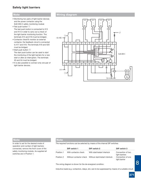
- Page 253 and 254: Safety light barriers System featur
- Page 255: Safety light barriers SLB 400 Techn
- Page 259 and 260: Safety light barriers Note • Moni
- Page 261 and 262: Safety light curtains and safety li
- Page 263 and 264: Safety light curtains and safety li
- Page 265 and 266: Safety light curtains and safety li
- Page 267 and 268: Safety light curtains and safety li
- Page 269 and 270: Safety light curtains and safety li
- Page 271 and 272: Safety light curtains with integrat
- Page 273 and 274: Safety light curtains with integrat
- Page 275 and 276: Reflection light sensor (Muting sen
- Page 277 and 278: Safety light curtains and safety li
- Page 279 and 280: Safety monitoring modules for optoe
- Page 281 and 282: Safety monitoring modules for optoe
- Page 283 and 284: Safety monitoring modules for optoe
- Page 285 and 286: Safety monitoring modules for optoe
- Page 287 and 288: SAFETY PRESSURE MATS 9 GENERAL PROD
- Page 289 and 290: Calculation of the safety distance
- Page 291 and 292: 67 SMS 4 safety mats accessories Sy
- Page 293 and 294: Safety mats Note • Protection of
- Page 295 and 296: FAIL-TO-SAFE SAFETY EDGES 9 SELECTI
- Page 297 and 298: SERIES SE ORDERING & ASSEMBLY INFOR
- Page 299 and 300: SERIES SE TECHNICAL DATA 9 Force/Tr
- Page 301 and 302: SERIES SE TECHNICAL DATA SE Series
- Page 303 and 304: SERIES SE TECHNICAL DATA Typical Wi
- Page 305 and 306: GENERAL & SPECIFIC-PURPOSE SAFETY C
- Page 307 and 308:
SAFETY CONTROLLER SELECTION CRITERI
- Page 309 and 310:
SERIES SRB 201 ZH & SRB 301 HC/R ME
- Page 311 and 312:
SERIES SRB 202 MSL MECHANICAL SPECI
- Page 313 and 314:
SERIES SRB 206 ST & SRB 206 SQ MECH
- Page 315 and 316:
SERIES SRB 211 AN MECHANICAL SPECIF
- Page 317 and 318:
SERIES SRB 211 ST MECHANICAL SPECIF
- Page 319 and 320:
SERIES SRB 301 LC & SRB 301 LCI MEC
- Page 321 and 322:
SERIES SRB 301 LC/B MECHANICAL SPEC
- Page 323 and 324:
SERIES SRB 301 MC MECHANICAL SPECIF
- Page 325 and 326:
SERIES SRB 301 ST SERIES SRB 301 ST
- Page 327 and 328:
SERIES SRB 324 ST MECHANICAL SPECIF
- Page 329 and 330:
SERIES SRB 202 C & SRB 400 C MECHAN
- Page 331 and 332:
SERIES SRB 401 LC MECHANICAL SPECIF
- Page 333 and 334:
SERIES SRB 402 EM & SRB 401 EM-115V
- Page 335 and 336:
SERIES SRB 504 ST MECHANICAL SPECIF
- Page 337 and 338:
SERIES PROTECT-IE MECHANICAL SPECIF
- Page 339 and 340:
SERIES PROTECT-PE MECHANICAL SPECIF
- Page 341 and 342:
Protect PSC 10 SELECTION GUIDE The
- Page 343 and 344:
Modular Safety System Representatio
- Page 345 and 346:
Modular Safety System Possible oper
- Page 347 and 348:
Terminal Assignment Modular Safety
- Page 349 and 350:
SAFE SPEED CONTROL 10 SELECTION GUI
- Page 351 and 352:
Examples of assembly Monitoring Sys
- Page 353 and 354:
10 Safer by Design 367
- Page 355 and 356:
AZS 2305 Typical Applications 10 Ty
- Page 357 and 358:
FWS 1205 Typical Applications 10 Ty
- Page 359 and 360:
FWS 1206 Typical Applications 10 Ty
- Page 361 and 362:
FWS 2505 Typical Applications 10 Ty
- Page 363 and 364:
FWS 2506 Typical Applications 10 Ty
- Page 365 and 366:
FWS 2105 Typical Applications 10 Ty
- Page 367 and 368:
FWS 2106 Typical Applications 10 Ty
- Page 369 and 370:
SSW 301HV Typical Applications 10 T
- Page 371 and 372:
AZR31S1 Typical Applications 10 Typ
- Page 373 and 374:
APPENDICES Topic Page • Selected
- Page 375 and 376:
Fail-to-Danger: a component or syst
- Page 377 and 378:
hazards present to the machine oper
- Page 379 and 380:
MACHINE SAFETY STANDARDS European M
- Page 381 and 382:
ANSI B11.16 Metal Powder Compacting
- Page 383 and 384:
SELECTED CONVERSION FACTORS TO CONV
- Page 385 and 386:
GENERAL TERMS & CONDITIONS OF SALE
- Page 387 and 388:
NOTES 401