S114D-12 - Teledyne Relays
S114D-12 - Teledyne Relays
S114D-12 - Teledyne Relays

You also want an ePaper? Increase the reach of your titles
YUMPU automatically turns print PDFs into web optimized ePapers that Google loves.
SERIES S114<br />
GENERAL ELECTRICAL SPECIFICATIONS (–65°C to +<strong>12</strong>5°C unless otherwise noted) (Notes 2 & 3)<br />
Contact Arrangement<br />
Rated Duty<br />
2 Form C (DPDT)<br />
Continuous<br />
Contact Resistance<br />
0.1 ohm max. before life; 0.2 ohm max. after life at 1A/28Vdc (measured 1/8" from header along lead)<br />
Contact Load Ratings (DC) Resistive: 1 Amp/28Vdc<br />
(See Fig. 3 for other DC<br />
Inductive: 200 mA/28Vdc (320 mH)<br />
resistive voltage/current ratings) Lamp: 100 mA/28Vdc<br />
Low Level: 10 to 50 μA/10 to 50mV<br />
Contact Load Ratings (AC)<br />
Resistive: 250 mA/115Vac, 60 and 400 Hz (Case undergrounded)<br />
100 mA/115Vac, 60 and 400 Hz (Case grounded)<br />
10,000,000 cycles (typical) at low level<br />
Contact Life Ratings<br />
1,000,000 cycles (typical) at 0.5A/28Vdc resistive<br />
100,000 cycles min. at all other loads specified above<br />
Contact Overload Rating 2A/28Vdc Resistive (100 cycles min.)<br />
Contact Carry Rating<br />
Contact factory<br />
Coil Operating Power 450 milliwatts typical at nominal rated voltage at 25°C<br />
Operate Time<br />
2.0 msec max. at nominal rated coil voltage<br />
Release Time S114 Series: 1.5 msec max. <strong>S114D</strong>, <strong>S114D</strong>D Series: 4.0 msec max.<br />
Contact Bounce<br />
1.5 msec max.<br />
Intercontact Capacitance 0.4 pf typical<br />
Insulation Resistance<br />
10,000 megohms min. between mutually isolated terminals<br />
Dielectric Strength Atmospheric pressure: 500 Vrms/60Hz 70,000 ft.: <strong>12</strong>5 Vrms/60Hz<br />
Negative Coil Transient (Vdc) <strong>S114D</strong>, <strong>S114D</strong>D 1.0 max<br />
Diode P.I.V. (Vdc) <strong>S114D</strong>, <strong>S114D</strong>D 100 min.<br />
DETAILED ELECTRICAL SPECIFICATIONS (–65°C to +<strong>12</strong>5°C unless otherwise noted) (Note 3)<br />
BASE PART<br />
NUMBERS<br />
(See Note 10 for full P/N example)<br />
S114-5<br />
<strong>S114D</strong>-5<br />
<strong>S114D</strong>D-5<br />
S114-6<br />
<strong>S114D</strong>-6<br />
<strong>S114D</strong>D-6<br />
S114-9<br />
<strong>S114D</strong>-9<br />
<strong>S114D</strong>D-9<br />
S114-<strong>12</strong><br />
<strong>S114D</strong>-<strong>12</strong><br />
<strong>S114D</strong>D-<strong>12</strong><br />
S114-18<br />
<strong>S114D</strong>-18<br />
<strong>S114D</strong>D-18<br />
S114-26<br />
<strong>S114D</strong>-26<br />
<strong>S114D</strong>D-26<br />
Coil Voltage (Vdc)<br />
Coil Resistance<br />
(Ohms ±10% @25°C)<br />
Coil Current (mAdc @25°C)<br />
(<strong>S114D</strong>D Series only)<br />
Pick-up Voltage (Vdc, Max.)<br />
Drop-out Voltage (Vdc)<br />
LOAD VOLTAGE (VDC)<br />
Nom. 5.0 6.0 9.0 <strong>12</strong>.0 18.0 26.5<br />
Max. 5.8 8.0 <strong>12</strong>.0 16.0 24.0 32.0<br />
S114, 114D 50 98 220 390 880 1560<br />
<strong>S114D</strong>D (Note 4) 39 78 220 390 880 1560<br />
(Note 5)<br />
Min. 93.2 57.8 33.0 25.6 17.5 14.8<br />
Max. <strong>12</strong>8.2 74.8 42.9 32.8 22.1 18.5<br />
S114, <strong>S114D</strong> 3.5 4.5 6.8 9.0 13.5 18.0<br />
<strong>S114D</strong>D 4.0 5.0 7.8 10.0 14.5 19.0<br />
S114, 114D<br />
Min. 0.14 0.18 0.35 0.41 0.59 0.89<br />
Max. 2.3 3.2 4.9 6.5 10.0 13.0<br />
<strong>S114D</strong>D<br />
Min. 0.6 0.7 0.8 0.9 1.1 1.4<br />
Max. 2.8 3.4 5.3 6.5 10.0 13.0<br />
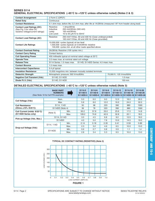
TYPICAL DC CONTACT RATING (RESISTIVE) (Note 2)<br />
300<br />
250<br />
200<br />
150<br />
100<br />
CENTIGRID ® AND TO-5<br />
50<br />
0 0.1 0.2 0.3 0.4 0.5 0.6 0.7 0.8 0.9 1.0<br />
LOAD CURRENT (AMPS DC)<br />
FIGURE 1<br />
S114 Page 2 SPECIFICATIONS ARE SUBJECT TO CHANGE WITHOUT NOTICE ©2003 TELEDYNE RELAYS<br />
www.teledynerelays.com<br />
S114/<strong>12</strong>03/Q1