Application Note Integration of a Low Noise ... - Ettus Research
Application Note Integration of a Low Noise ... - Ettus Research
Application Note Integration of a Low Noise ... - Ettus Research

Create successful ePaper yourself
Turn your PDF publications into a flip-book with our unique Google optimized e-Paper software.
<strong>Application</strong> <strong>Note</strong><br />
<strong>Integration</strong> <strong>of</strong> a <strong>Low</strong> <strong>Noise</strong> Amplifier and a USRP Device<br />
<strong>Ettus</strong> <strong>Research</strong><br />
Universal S<strong>of</strong>tware Radio Peripheral<br />
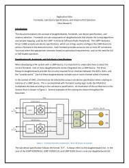
Introduction<br />
Some applications require receivers to maintain extraordinarily low noise figure (NF). In these cases, it<br />
is possible to use an external low-noise amplifier (LNA) to improve the cascaded NF <strong>of</strong> the USRP<br />
(Universal S<strong>of</strong>tware Radio Peripheral). This application note provides directions on how to install and<br />
power an external LNA with a <strong>Ettus</strong> <strong>Research</strong> USRP hardware and/or Bias-Ts.<br />
Why Use an LNA<br />
An LNA is typically used to provide low noise gain as close as possible to the antenna. Sometimes,<br />
especially in GPS receiver applications, the LNA is integrated into an active antenna. The ultimate<br />
effect is a reduction in receiver’s noise figure achieved by amplifying the desired signal before it is<br />
attenuated by other, passive components in the receiver chain.<br />
NF Performance <strong>of</strong> the USRP and Daughterboards<br />
The NF <strong>of</strong> a USRP hardware-based receiver ranges from 5-13 dB and depends on the daughterboard<br />
selected. This parameter may vary from unit to unit, and is specified with maximum receiver gain<br />
settings.<br />
LNA <strong>Integration</strong> with the USRP Devices<br />
Generally, a wireless system designed with a USRP radio will utilize connectorized LNAs. Mini-Circuits®<br />
is a common source for these LNAs. In some cases, the LNA may be a component within the antenna.<br />
Example part numbers for a variety <strong>of</strong> LNAs and active antennas are shown in Table 1 and Table 2. The<br />
discussions about power distribution are applicable to both external LNAs and active antennas.<br />
Min Freq<br />
(MHz)<br />
Max Freq<br />
(MHz)<br />
Gain<br />
(dB)<br />
P1DB<br />
(dB)<br />
NF<br />
(dB)<br />
IIP3<br />
(dBm)<br />
Currrent<br />
(mA)<br />
Voltage<br />
(V)<br />
ZFL-1000N+ 0.1 1000 20 3 2.9 14 60 15<br />
ZX60-33LN+ 50 3000 13 16.5 1.1 32 88 5<br />
ZEL-0812LN 800 1200 20 8 1.5 18 70 15<br />
ZX60-542LN+ 4400 5400 24 10 1.9 23 80 12<br />
LNA-1575-349 1555 1595 8 20 1.9 24 100 5.5-18<br />
Table 1- LNAs from Mini-Circuits
Min Freq<br />
(MHz)<br />
Max<br />
Freq<br />
(MHz)<br />
Ant.<br />
Gain<br />
(dB)<br />
LNA<br />
Gain<br />
(dB)<br />
LNA NF<br />
(dB)<br />
LNA<br />
IIP3<br />
(dBm)<br />
Currrent<br />
(mA)<br />
Voltage<br />
(V)<br />
UC-4364-513 435 438 18 No Spec 1 14 50 5-15<br />
UL-1501- 100 3000 15 12 1.8 33 125 5-15<br />
B384<br />
UC-1574-341 1565 1585 17 No Spec 1.9 24 100 5.5-18<br />
Table 2- Active Antennas<br />
Powering an External LNA or Active Antenna<br />
There are two general methods used to provide power to an external LNA; coaxially or with an<br />
independent power connection. The method required will depend on the selected LNA,<br />
daughterboard and power requirements.<br />
Many LNAs and active antennas require power to be applied to the conductor <strong>of</strong> the coaxial cable,<br />
which also acts as the path for the RF signal. This requires some method to isolate the receiver input<br />
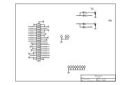
from the DC component, which usually requires AC coupling via a capacitor, or a Bias-T. The<br />
functional model for a Bias-T is shown in Figure 1.<br />
Figure 1-Schematic Representation <strong>of</strong> Bias-T
Powering an External LNA with a DBSRX2 Daughterboard<br />
In order to provide easy access to DC power for common applications such as GPS reception, the<br />
DBSRX2 daughterboard includes an on-board Bias-T, which is enabled by populating and shorting<br />
jumper J101 on the board. This configuration provides a 3.3V power supply to the conductor <strong>of</strong> the RF<br />
connector via a 27 nH inductor. The purpose <strong>of</strong> the inductor is to filter any potential noise sources<br />
that may interfere with the RF reception <strong>of</strong> the DBSRX2.<br />
<strong>Note</strong> the current sourced by this Bias-T should be limited to 100 mA. Any additional current will<br />
damage the in-line inductor, and could change the impedance <strong>of</strong> the circuit. This will reduce the<br />
receive performance <strong>of</strong> the DBSRX2, and could potentially lead to damage <strong>of</strong> other components<br />
within the system.<br />
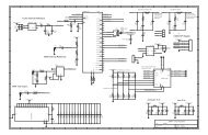
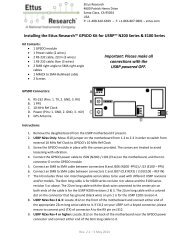
The schematic <strong>of</strong> the DBSRX2 daughterboard, and a photo <strong>of</strong> the jumper configuration, can be seen in<br />
figures Figure 2 and Figure 3, respectively.<br />
Figure 2- DBSRX2 Daughterboard Bias-T Schematic
Figure 3- DBSRX-2 Daughterboard with Bias-T Jumper Enabled<br />
Power an External LNA with All Other Daughterboards (not DBSRX2)<br />
The DBSRX2 is the only daughterboard available from <strong>Ettus</strong> <strong>Research</strong> that provides an on-board Bias-T.<br />
All other daughterboards require an external Bias-T if DC power provided via coaxial connection. As<br />
mentioned, Mini-Circuits is a common supplier <strong>of</strong> coaxial Bias-T's, and generally provide wide<br />
bandwidth capability and relative low insertion loss. One example is the ZFBT-6G+, which is<br />
approximately $80 in per unit (as <strong>of</strong> Feb 2012). This provides coverage from 10 MHz to 6 GHz. The<br />
ZFBT-4R2GW+ is more ideal for applications utilizing the BasicRX daughterboard.<br />
Other LNAs with similar properties and a variety <strong>of</strong> packaging options are available at:<br />
Conclusion<br />
http://www.minicircuits.com/products/bias_tees_coax.html<br />
This application note examined some sources for LNAs and active antennas and methods to integrate<br />
the LNA into a receiver system based on the <strong>Ettus</strong> <strong>Research</strong> USRP hardware. If you have any questions<br />
on this application note, please send them to support@ettus.com.<br />
References<br />
Mini-Circuits. (n.d.). Mini-Circuits . Retrieved February 15, 2012, from<br />
http://www.minicircuits.com/products/amplifiers_coax_low_noise.shtml<br />
Myers Engineering International, Inc. (n.d.). Retrieved February 15, 2012, from Antenna<br />
Store: http://www.antennas.us/