Design Process for Smart, Distributed RF Sensors - Ettus Research
Design Process for Smart, Distributed RF Sensors - Ettus Research
Design Process for Smart, Distributed RF Sensors - Ettus Research

Create successful ePaper yourself
Turn your PDF publications into a flip-book with our unique Google optimized e-Paper software.
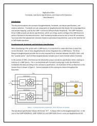
Introduction<br />
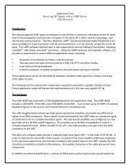
Application Note<br />
<strong>Design</strong> <strong>Process</strong> <strong>for</strong> <strong>Smart</strong>, <strong>Distributed</strong> <strong>RF</strong> <strong>Sensors</strong><br />
<strong>Ettus</strong> <strong>Research</strong><br />
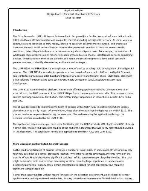
The <strong>Ettus</strong> <strong>Research</strong> USRP (Universal Software Radio Peripheral) is a flexible, low-cost software defined radio<br />
(SDR) used to create many capable and unique <strong>RF</strong> systems, including intelligent <strong>RF</strong> sensors. As use of wireless<br />
communications continues to grow rapidly, limited <strong>RF</strong> spectrum becomes more crowded. This creates an<br />
increased demand <strong>for</strong> <strong>RF</strong> sensors that can monitor the spectrum in an ef<strong>for</strong>t to measure wireless traffic<br />
conditions, detect illegal interferes, or per<strong>for</strong>m other signals intelligence tasks. For example, the evolution of<br />
whitespace radios depends on <strong>RF</strong> monitoring capability to reduce co-channel interference between competing<br />
devices. Organizations in the civilian, defense, and homeland security segments all rely on <strong>RF</strong> sensors in<br />
greater numbers to identify, characterize, and locate various targets.<br />
The USRP N210 and USRP E110 are a complimentary set of devices enabling rapid development of intelligent <strong>RF</strong><br />
sensors. The USRP N210 is intended to operate as a host-based software radio plat<strong>for</strong>m. A Gigabit Ethernet<br />
(GigE) interface provides a digital, baseband interface <strong>for</strong> a receive and transmit chain. GNU Radio, along with<br />
other software frameworks and tools such as GNU Radio Companion (GRC), accelerate custom radio<br />
development.<br />
The USRP E110 is an embedded plat<strong>for</strong>m. Rather than offloading application-specific DSP operations to an<br />
external host, the ARM processor of the USRP E110 per<strong>for</strong>ms these operations internally. This processor runs a<br />
custom built Angstrom Linux distribution. The factory-image supplied on an SD card also includes GNU Radio<br />
and GRC.<br />
This allows developers to implement intelligent <strong>RF</strong> sensors with a USRP N210 in a lab setting where various<br />
algorithms can be easily tested. After validation, these algorithms can then be deployed on a USRP E110. This<br />
process can be as simple as transferring the associated files and executing the applications through the<br />
network interface provided by the USRP E110.<br />
This application note assumes you have some familiarity with the USRP products, GNU Radio, and GRC. If this is<br />
not the case, you can find suggested reading at the end of the document that will clarify many things discussed<br />
in this document. This application note is also applicable to the USRP N200 and USRP E100.<br />
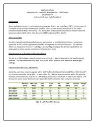
More Discussion on <strong>Distributed</strong>, <strong>Smart</strong> <strong>RF</strong> <strong>Sensors</strong><br />
As the need <strong>for</strong> distributed <strong>RF</strong> sensors increases, a number of issues arise. In some cases, <strong>RF</strong> sensors may only<br />
relay raw data back to a central processing location. While this has some advantages, systems relying on the<br />
transfer of raw <strong>RF</strong> samples require significant back-haul infrastructure to support large bandwidths. This data<br />
might be transferred to some central processing location, requiring large, sophisticated, and expensive<br />
processing plat<strong>for</strong>ms. In many cases, signals collected are recorded <strong>for</strong> post processing, thus requiring<br />
significant storage capability.<br />
Rather than supplying data without regard <strong>for</strong> events in the detection environment, an intelligent <strong>RF</strong> sensor<br />
applies various techniques to reduce the data. In turn, this reduces requirements <strong>for</strong> back-haul infrastructure,
data storage, and centralized processing. Deploying smart <strong>RF</strong> sensors requires some knowledge about the<br />
signals of interest. This can present some disadvantages if the distributed sensors are not flexible and easily<br />
reconfigured <strong>for</strong> new conditions.<br />
The availability of tools such as the USRP product family and GNU Radio, provides a path to develop intelligent<br />
<strong>RF</strong> sensors with ease and agility. Software radios, such as the USRP, and flexible development tools are key<br />
pieces of a strategy of deploying smart, distributed <strong>RF</strong> sensors.<br />
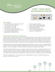
The USRP Hardware Driver<br />
Figure 1 - <strong>Distributed</strong>, <strong>Smart</strong> <strong>RF</strong> Sensor Network<br />
The USRP Hardware Driver (UHD) provided by <strong>Ettus</strong> <strong>Research</strong> allows users to develop software defined radios<br />
in a GNU Radio, LabVIEW, Matlab, Simulink, or custom SDR frameworks. Operating in Windows, Linux, or<br />
MacOS, UHD provides an abstraction layer between the software radio and the USRP device. This allows<br />
applications developed with UHD to maintain compatibility with all USRP models.<br />
UHD provides an easy method to move SDR applications across USRP plat<strong>for</strong>ms. In this example, applications<br />
are developed on a host-PC with a USRP N10, and then seamlessly migrated to a USRP E110. This enables the<br />
flexibility required <strong>for</strong> changing <strong>RF</strong> environments and signal collection missions.
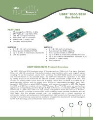
The USRP E110 and USRP N210<br />
The USRP N210 is a member of the Network Series of products. It is generally connected to a host computer<br />
via a Gigabit Ethernet interface that can provide up to 25 MS/s of 16-bit samples, and 50 MS/s of 8-bit samples.<br />
It contains a Spartan 3A-DSP 3400 FPGA, a 100 MS/s, 14-bit ADC, a 400 MS/s, 16-bit DAC, and other<br />
components to support operation. The USRP N210 also provides various mechanisms to synchronize multiple<br />
units <strong>for</strong> phase coherent operation. This can be accomplished with an <strong>Ettus</strong> <strong>Research</strong> MIMO cable, or with<br />
externally distributed 10 MHz and 1 PPS signals. The USRP N210 also includes an optional GPS disciplined<br />
oscillator <strong>for</strong> synchronization over wide areas.<br />
The USRP E110 is a unique device that incorporates an ARM-based computer-on-a-module (COM). This<br />
embedded computer is shipped with a fully functional Linux distribution with GNU Radio and other useful<br />
software installed. This makes the USRP E110 ideal <strong>for</strong> standalone operation as a smart, distributed <strong>RF</strong> sensor.<br />
The USRP E110 provides several interfaces to achieve application requirements: HDMI output, audio in/out,<br />
USB, 10/100 Ethernet ports, and a USB based debug port. Multiple USRP E110s can be time synchronized with<br />
external 10 MHz and 1 PPS inputs. An optional GPSDO module can also be used to time synchronize multiple<br />
USRP E110s over a wide geographic area. The USRP E110 uses the same FPGA as the USRP N210, a 12-bit, 64<br />
MS/s ADC, and 14-bit 128 MS/s DAC. Both models are supported by UHD.<br />
Figure 1 - USRP E100<br />
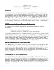
Unique Development <strong>Process</strong> Enabled by UHD and USRP Devices<br />
The portability offered by UHD allows the user to exploit a wide array of development tools. These include<br />
graphical development environments, text-based programming languages such as C++ or Python, and in some<br />
cases, third-party products with application-specific functions. In this example, GNU Radio and Python are used<br />
to generate a smart <strong>RF</strong> detection algorithm. This algorithm is verified in a lab setting with an <strong>RF</strong> signal<br />
generator. Finally, the application is deployed <strong>for</strong> operation on a “remote” USRP E110. An illustration of this<br />
development concept can be seen in Figure 1.
Figure 2 - Application Development <strong>Process</strong><br />
Several other tools are at your disposal when development occurs on a host-based PC. Sophisticated<br />
development environments, such as LabVIEW or MATLAB, can be used <strong>for</strong> various pre-and-post-processing<br />
functions to verify these algorithms. In some cases you may also modify FPGA designs to support the algorithm<br />
and transfer these designs to the USRP E110 with the other software components.<br />
In the end, this approach combines the best of both worlds – accessibility and convenience on a host-based<br />
plat<strong>for</strong>m, and the deployability of the USRP E110.<br />
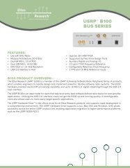
Simple Application Example – <strong>RF</strong> Power Detection Mission<br />
To illustrate the power of this development concept, <strong>Ettus</strong> <strong>Research</strong> assembled a simple demonstration. The<br />
objective of this example is to implement a straight <strong>for</strong>ward power detection algorithm on the USRP E110. The<br />
goal is to simultaneously listen on five consecutive 25 kHz channels, and issue a report to the back-haul<br />
network when transmission starts or subsides in each of those channels. For clarity, the channel arrangement<br />
<strong>for</strong> the detection algorithm is shown in Figure 3. Power detection and threshold operations are per<strong>for</strong>med on<br />
each channel independently. The output of the threshold operation will be used to generate reports of<br />
transmitters, starting and stopping operation in the particular channel. These transitions will be reported to<br />
another entity on the back-haul network with a specific IP address and port number.<br />
Simple algorithms like this are often used to detect the presence of interferers within shared spectrum. More<br />
sophisticated algorithms may also be helpful in calculating the density of <strong>RF</strong> communications on a particular<br />
channel, such as those used <strong>for</strong> whitespace communications.
Figure 3 - Channelization Scheme <strong>for</strong> Example (not to scale)<br />
In order to meet the detection requirements <strong>for</strong> this example, you have several tools heart your disposal.<br />
Graphical tools like GRC, are useful <strong>for</strong> DSP development, but text- based programming methods may also be<br />
used. Figure 4 shows several components used to implement this example. The USRP device provides the<br />
hardware required to sample the <strong>RF</strong> spectrum. UHD provides a common API <strong>for</strong> all USRP devices. GNU Radio<br />
provides stream-based DSP capability, and the Python script provides the developer an easy way to implement<br />
reporting logic. Finally, the detection reports re sent to the network with a socket interface from the Python<br />
script.<br />
Figure 4 - Power Detector - Hardware and Software Components<br />
Implementation Step 1 – Rapid Development on Host Plat<strong>for</strong>m<br />
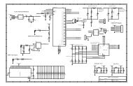
The implementation used to meet these objectives is fairly straight <strong>for</strong>ward. GNU Radio is used to per<strong>for</strong>m<br />
stream based processing tasks, such as channelization, power detection, and thresholding. GRC was used to<br />
synthesize code <strong>for</strong> these functions. The general architecture <strong>for</strong> this DSP chain is shown in Figure 5, and<br />
screenshot of the flowgraph as drawn in GRC can be seen in Figure 6 and Figure 7. This flowgraph outputs a<br />
stream of bytes to a file. The five LSBs of the byte represent the power detection state of each channel. A Unix<br />
Pipe (FIFO) is used as an inter-application interface to another program, which per<strong>for</strong>ms additional processing.
Figure 5 - GNU Radio Flow Graph Architecture<br />
A complex multiplication and sine signal source set to the channel offset frequency is used to per<strong>for</strong>m<br />
frequency translation of the baseband signal. Each channel is low pass filtered with a bandwidth of 18 kHz.<br />
Other components such as the Frequency Translating FIR Filter could be used to combine these to functions in<br />
a single block. GNU Radio also provides a Polyphase Channelizer block. This more discrete implementation was<br />
chosen <strong>for</strong> the sake of illustration. An RMS function with parameterized time constant is used to estimate the<br />
power of each channel. The user-defined threshold is subtracted from the result and a binary slicer is used to<br />
provide a binary indication of <strong>RF</strong> power. The bit <strong>for</strong> each channel is effectively shifted to the corresponding<br />
channel position within a single byte using multiplication and addition. This is output to an external file sink –<br />
in this case, set to a pipe named “detect_fifo.”<br />
The flowgraph includes several parameters, such as detection threshold, and center channel frequency, set<br />
through a command line interface. This allows you to adjust <strong>for</strong> changing targets and environments without<br />
changing hard-coded values.<br />
TODO: THIS GRAPHIC WILL BE UPDATED W/ LATEST VERSION!!!!
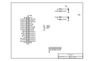
Figure 6 - GNU Radio Flow Graph - Channelization w/ Complex Multiplication and Complex LPF<br />
Figure 7 - GRC Flow Graph - Power Detection and Byte Packing<br />
While GNU Radio is ideal <strong>for</strong> stream based DSP operations, sometimes other tools such as text-based<br />
programming languages are more appropriate <strong>for</strong> asynchronous or logical programming. A Python script was<br />
used to implement a simple state machine to produce reports <strong>for</strong> transmit start (“Tx On”) and transmit stop<br />
(“Tx Off”) events. Accepting bytes from the pipe, which is fed by the GNU Radio flowgraph, the Python<br />
application interprets bit transitions, and generates textual reports. These textual reports are output to a UDP<br />
socket. This UDP socket shares this in<strong>for</strong>mation with other devices on the back-haul network. The code <strong>for</strong> this<br />
example can be found in the appendix.<br />
Plugging in a host-based USRP device, such as the USRP N210, this program can be executed and the algorithms<br />
can be validated with real <strong>RF</strong> signals be<strong>for</strong>e remote deployment.
Implementation Step 2 – Lab Verification<br />
During and after algorithm development, it is important to validate the per<strong>for</strong>mance of the application with<br />
reference signals. The simple nature of this examples, allows the algorithms to be tested with a run-of-the-mill<br />
<strong>RF</strong> signal generator. A block diagram of the apparatus used <strong>for</strong> verification can be seen in Figure 8.<br />
Figure 8 - Testing Sensor Application with Lab Equipment<br />
The signal generator was used to produce <strong>RF</strong> signals of various amplitudes and frequencies while the<br />
applications were running. Turning <strong>RF</strong> on, and sweeping the frequency from below the lowest channel to a<br />
value above the highest channel produces a report, such as the one shown in Figure 10. This makes intuitive<br />
sense if you refer to the spectral illustration of Figure 3. The default threshold and gain values set in the<br />
application correspond to a signal power of approximately -100 dBm with an SBX daughterboard. The<br />
application generates a report when a transition across this boundary occurs in each channel. As the frequency<br />
is swept, the power may exceed this threshold in an adjacent channel be<strong>for</strong>e falling below the threshold in the<br />
current channel. This is due to a course frequency step moderate overlap in the passband of the channel filters.
Figure 9 - Host Execution of Flow Graph (900 MHz, threshold -70 dBfs, 250 kS/s)<br />
Figure 10 - Host Execution of smart_rf_sensor_demo.py - <strong>RF</strong> Sweep Across Channelizer Centered at 900 MHz
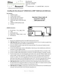
Implementation Step 3 – Algorithm Deployment<br />
After developing and testing a new <strong>RF</strong> detection algorithm, this algorithm can be deployed on the USRP E110<br />
plat<strong>for</strong>m. In many cases this is as simple as transferring the files to the USRP E110 SD card and executing the<br />
applications. The USRP E110 can be accessed through an SSH connection, available through the 10/100<br />
Ethernet port. You can transfer these files by mounting the USRP file system with gvfs-mount. For more<br />
instructions on this items see the USRP E100/110 FAQ:<br />
http://code.ettus.com/redmine/ettus/projects/usrpe1xx/wiki/FAQ<br />
After transferring the files, you can execute the application. If both programs have been copied to the home<br />
folder of the root account of the USRP E110, the commands to run the programs will con<strong>for</strong>m to those shown<br />
in Figure 11 and Figure 12Error! Reference source not found.. Figure 13 shows the output of the application<br />
displayed on a remote machine listening on the appropriate UDP socket. In this case, the USRP E110 was<br />
located near and connected to an externally mounted antenna to allow observation of real-world signals. The<br />
USRP E110 is accessed remotely from an office computer. The flowgraph is tuned to the Family Radio Service<br />
(FRS) band, and the reports show bursting radio traffic. These reports are verified visually with a USRP N210based<br />
spectrum analyzer connected to an adjacent antenna.<br />
Figure 11 - SSH Execution of power_event_frontend_demo.py (464.4 MHz, threshold -70 dBFS, 125 kS/s)
Figure 12 - SSH Execution of smart_rf_sensor_demo.py (receive from PIPE named detect_fifo, output reports to<br />
192.168.1.159:8002, verbose not enabled)<br />
Figure 13 - <strong>Distributed</strong> Sensor Output - Received by Remote Host on Port 8002<br />
The GNU Radio flowgraph and Python script were both implemented with command line arguments allowing<br />
you to adjust various parameters. For example, the noise floor and total gain of the SBX varies across<br />
frequency, so a log-threshold argument is used to accommodate <strong>for</strong> these variations. A complete list of these<br />
arguments can be provided by including “—help” in the command line. Successful deployment of this<br />
application may require adjustment of the log-threshold parameter. Different sample rates must also be<br />
specified because the USRP N210 output rate cannot be reduced down to 125 kS/s as the USRP E110 can.<br />
Considerations in DSP <strong>Design</strong> – USRP E110 vs. USRP N210<br />
When designing a portable application <strong>for</strong> USRP devices, it’s important to note the sample reference clock on<br />
the USRP N210 is fixed at 100 MHz. The USRP E100/E110 provides a flexible-frequency clocking solution, with a<br />
maximum and default frequency of 64 MHz. In both cases, the sample rate used by a portable application must<br />
be set to a factor of these frequencies. You must consider these differences when porting code from a USRP<br />
N210-based system to a USRP E110. This can be accomplished by choosing sample rates that are common<br />
factors of 100 MHz and 64 MHz. It is also possible to use a rational re-sampler configured to work with
different data rates. If any of this is unclear, you should reference additional resources in the knowledge base<br />
<strong>for</strong> a better understanding of the USRP clocking systems.<br />
You should also consider the difference in ADC and DAC resolution. The USRP E110 ADC and DAC provide 12<br />
and 14 bits of resolution, respectively. The USRP N210 ADC and DAC provide 14 and 16 bit of resolution,<br />
respectively. This will impact spurious free dynamic range, and to a lesser extent, noise figure.<br />
It is important to proceed with an understanding of the USRP E110’s processing capabilities. The OMAP<br />
processor used in the device is a low-power, small-<strong>for</strong>m-factor computer. It does not provide the processing<br />
per<strong>for</strong>mance required to implement complicated algorithms at the same rates as a host-based system. This<br />
example runs at approximately 125 kS/s. 1 MS/s is the maximum rate typically achieved when GNU Radio is<br />
used on the USRP E110. However, this figure is highly dependent on the complexity of the flowgraph.<br />
Optimized routines can improve this figure. These can be implemented with custom frameworks, or with<br />
Vector Optimized Library of Kernels (VOLK), which is a component within GNU Radio facilitating deployment of<br />
efficient, vectorized math routines.<br />
Possibilities<br />
The power detection example used in this application note is intended to be fairly simple and easy to<br />
understand. This application may be useful <strong>for</strong> users looking to evaluate traffic in particular bands. However, it<br />
is more interesting to note you can deploy more complex algorithms than this simple power detector. For<br />
example, decoders <strong>for</strong> various digital standards can be integrated into the application to identify and tag <strong>RF</strong><br />
targets. Also, some USRP users have made external provisions <strong>for</strong> direction finding. There is enormous<br />
potential to deploy smart, distributed <strong>RF</strong> sensors using the USRP E110 and the principles discussed in this<br />
document. The USRP E110 can also transmit signals to provide stimulus <strong>for</strong> various events.<br />
Sophisticated users with experience in FPGA development can take advantage of the un-utilized resources of<br />
the Xilinx Spartan-3A DSP 3400 FPGA. This can drastically increase the processing per<strong>for</strong>mance of the system,<br />
and reduce the amount of data that must be handled by the slower OMAP processor. The DSP chains in the<br />
USRP E110 and USRP N210 are identical on the “host-side” of the rate conversion blocks (decimators,<br />
interpolators). As with processor-based implementations, FPGA modifications can be verified in a lab with the<br />
USRP N210, and ported to the USRP E110. This requires compilation and timing verification <strong>for</strong> each model,<br />
which provides <strong>for</strong> a less streamlined deployment compared to this example implemented with GNU Radio.
Conclusions<br />
This document presents a flexible method to deploy and reconfigure a system of smart, distributed <strong>RF</strong> sensors.<br />
The application presented shows a clear path to develop and test various DSP algorithms in the lab, and how to<br />
easily deploy them to remote sensors. This is appropriate <strong>for</strong> a variety of applications requiring agile use of<br />
distributed <strong>RF</strong> systems. If you have any questions about this document or the USRP devices, please refer to the<br />
Knowledge Base on the <strong>Ettus</strong> <strong>Research</strong> website or contact support@ettus.com. If you would like to make a<br />
sales inquiry, please contact sales at sales@ettus.com. You can access the GRC files and code <strong>for</strong> this example<br />
at:<br />
http://files.ettus.com/app_notes/distributed_rf_sensors/smart_rf_sensor_demo.zip<br />
Suggested Reading<br />
http://gnuradio.org/redmine/projects/gnuradio/wiki<br />
www.ettus.com
import time<br />
import socket<br />
import thread<br />
import string<br />
import struct<br />
from optparse import OptionParser<br />
CHANNEL_COUNT = 5<br />
state_array = [0,0,0,0,0] #channel power state array<br />
def report_event(channel_num, event_string, network_socket, options):<br />
#assemble report string and output to udp socket<br />
report_string = time.asctime(time.gmtime(time.time())) + ',' + event_string + ',' + 'Chan. ' +<br />
str(channel_num)<br />
network_socket.sendto(report_string + "\n\r",(options.ip, options.port) )<br />
if(options.verbose):<br />
print report_string<br />
def apply_detection_logic(file_object,network_socket,options):<br />
#get byte from fifo<br />
byte = int(struct.unpack('B', file_object.read(1))[0])<br />
#look at CHANNEL_COUNT LSBs to determine if power is detected<br />
<strong>for</strong> j in range(0,CHANNEL_COUNT):<br />
def main():<br />
result = ( byte >> j ) & 1<br />
#apply simple logic to determine TX on/off transission<br />
if state_array[j] == 0:<br />
if result == 1:<br />
report_event(j,"Tx On",network_socket,options)<br />
if state_array[j] == 1:<br />
if result == 0:<br />
report_event(j,"Tx Off",network_socket,options)<br />
state_array[j] = result<br />
#command parser
parser = OptionParser()<br />
parser.add_option("-p", "--port", dest="port",action="store",type="int",<br />
help="Port <strong>for</strong> outging UDP Socket.", metavar="PORT")<br />
parser.add_option("-a", "--address", dest="ip",action="store",type="string",<br />
help="IP Address <strong>for</strong> outgoing UDP Socket.", metavar="ADDR")<br />
parser.add_option("-f", "--file", dest="filename",action="store",type="string",<br />
help="File w/ incoming bytes", metavar="FILE")<br />
parser.add_option("-v", action="store_true", dest="verbose",help="Print reports to stdout.",<br />
default=False)<br />
(options, args) = parser.parse_args()<br />
print "The program is starting"<br />
#open file pipe <strong>for</strong> itnerface to flow graph<br />
print "Opening Pipe to GNU Radio Flow Graph"<br />
file = open(options.filename,"rb")<br />
#bind UDP socket<br />
print "Opening Outgoing UDP Socket"<br />
sock_network = socket.socket(socket.AF_INET, socket.SOCK_DGRAM)<br />
#process output from gnuradio flowgraph<br />
while(1):<br />
apply_detection_logic(file,sock_network,options)<br />
if __name__ == "__main__":<br />
main()