Application Note Receiving HF Signals with a ... - Ettus Research
Application Note Receiving HF Signals with a ... - Ettus Research
Application Note Receiving HF Signals with a ... - Ettus Research

You also want an ePaper? Increase the reach of your titles
YUMPU automatically turns print PDFs into web optimized ePapers that Google loves.
<strong>Application</strong> <strong>Note</strong><br />
<strong>Receiving</strong> <strong>HF</strong> <strong>Signals</strong> <strong>with</strong> a USRP Device<br />
<strong>Ettus</strong> <strong>Research</strong><br />
Introduction<br />
The electromagnetic (EM) spectrum between 3 and 30 MHz is commonly referred to as the <strong>HF</strong> band.<br />
Due to the propagation characteristics of signals in this band, <strong>HF</strong> is often used for long range, overthe-horizon<br />
communication. The <strong>Ettus</strong> <strong>Research</strong> USRP (Universal Software Radio Peripheral) is an<br />
ideal candidate for experimentation <strong>with</strong> <strong>HF</strong> communications, as it can directly sample the entire <strong>HF</strong><br />
band. The USRP software defined radio is also supported by several software frameworks, including<br />
LabVIEW, GNU Radio, Simulink and others. Using the USRP hardware and available software, it is<br />
possible to experiment in several different application areas, including:<br />
• Reception of worldwide shortwave radio broadcasts<br />
• Two-way voice and data communications in SSB, CW, RTTY and other modes<br />
• International timing broadcasts<br />
• Scientific purposes, including ionospheric characterization and space weather<br />
These applications can be of interested to educators, amateur radio operators, military and many<br />
other types of users.<br />
The following section outlines the components required to assemble a capable, flexible receiver.<br />
Future application notes will discuss the implementation of a full, two-way capable <strong>HF</strong> rig.<br />
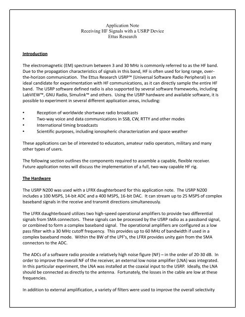
The Hardware<br />
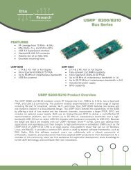
The USRP N200 was used <strong>with</strong> a LFRX daughterboard for this application note. The USRP N200<br />
includes a 100 MSPS, 14-bit ADC and a 400 MSPS, 16-bit DAC. It can stream up to 25 MSPS of complex<br />
baseband signals in the receive and transmit directions simultaneously.<br />
The LFRX daughterboard utilizes two high-speed operational amplifiers to provide two differential<br />
signals from SMA connectors. These signals can be processed by the USRP radio as a passband signal,<br />
or combined to form a complex baseband signal. The operational amplifiers are configured as a low<br />
pass filter <strong>with</strong> a 30 MHz cutoff frequency. This provides up to 60 MHz of bandwidth if used in a<br />
complex baseband mode. Within the BW of the LPF's, the LFRX provides unity gain from the SMA<br />
connectors to the ADC.<br />
The ADCs of a software radio provide a relatively high noise figure (NF) – in the order of 20-30 dB. In<br />
order to improve the overall NF of the receiver, an external low noise amplifier (LNA) was integrated.<br />
In this particular experiment, the LNA was installed at the coaxial input to the USRP. Ideally, the LNA<br />
should be connected as directly to the antenna. Fortunately, the losses in the cable are low at these<br />
frequencies.<br />
In addition to external amplification, a variety of filters were used to improve the overall selectivity
and dynamic range of the receiver. While the LFRX does provide some rejection of signals above 30<br />
MHz, additional filtering provides additional attenuation of in-band and out-of-band interferes that<br />
are substantially stronger than the weak signals that can potentially be received in the <strong>HF</strong> band.<br />
Examples of interferes include FM and AM broadcast, television broadcast, etc. These signals are<br />
produced <strong>with</strong> hundreds of kW's of power, and are <strong>with</strong>in a hundred miles of the receiver. Thus, they<br />
are significantly stronger than the weak <strong>HF</strong> signals we're attempting to receive, which arrive from<br />
thousands of miles away.<br />
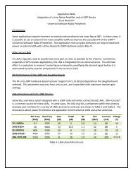
Table 1 shows the filters used in this apparatus and the frequencies they pass. The DC-32 MHz filter<br />
was used to provide the most flexibility, but allows strong in-band interferes to pass leading to reduce<br />
dynamic range in the receiver. The best results were achieved <strong>with</strong> the SBP-30+ filter – 27, which<br />
provides access to several signals of interest, including the amateur 10 Meter band. The cascaded NF<br />
of the cabling, BPF, LNA and USRP hardware is approximately 14 dB. <strong>HF</strong> atmospheric noise is<br />
significantly higher than the natural, thermal noise floor, so a very low noise figure is generally not<br />
useful.<br />
Filter<br />
SLP-30+<br />
SLP-30+<br />
SBP-21.4+<br />
Table 1- Tested Filters<br />
Passband Frequency<br />
DC-32 MHz<br />
27-33 MHz<br />
19.2-23.6 MHz<br />
A photo of the one of the filters and LNA used in this setup can be seen in Figure 1.<br />
Figure 1- <strong>HF</strong> BPF and Combined <strong>with</strong> Wideband LNA<br />
In order to experiment easily and quickly, an antenna present on the <strong>Ettus</strong> <strong>Research</strong> lab roof was used<br />
for this testing. This is a discone antenna intended for operation between 50 MHz and 1 GHz.<br />
Although the antenna was not optimized for <strong>HF</strong> reception, it is still more than capable of receiving<br />
interesting signals.
The Software<br />
In order to demonstrate the flexibility, and low time investment required to experiment <strong>with</strong> a variety<br />
of transmission modes, GNU Radio software was utilized to perform the digital signal processing<br />
necessary to receive, demodulated and display the signals of interest. A modified version of the SSB<br />
receiver designed by OZ9AEC, Alexander Csete, was used for this experiment, further proving that<br />
USRP radio operators can benefit from the open source environment. Csete’s GNU Radio Companion<br />
(GRC) flowgraph was modified to use the UHD (USRP Hardware Driver) source, providing the greatest<br />
flexibility for use <strong>with</strong> all USRP models.<br />
The final flow graph, which can be downloaded from the <strong>Ettus</strong> <strong>Research</strong> website, can be seen in Figure<br />
2. Due to screen size resolutions, some graphical components of the flowgraph are cutoff, but the<br />
primary DSP blocks are all visible.<br />
Figure 2-Simple GRC Flowgraph - This was used to implement a very capable <strong>HF</strong> receiver. Due to<br />
screen resolution limitations, some processing blocks are clipped, but the most important blocks are<br />
shown.<br />
The Experiment<br />
As mentioned, the <strong>HF</strong> band provides access to a wide variety of signals from around the world. The<br />
signals received during this experiment included amateur radio operators, shortwave broadcasts from<br />
the UK and South America, and beacons that are to test the propagation <strong>with</strong>in the <strong>HF</strong> band at several<br />
different frequencies. Screenshots of the receiver application implemented in Figure 2 can be seen in<br />
Figure 3 and Figure 4. Figure 3 shows the reception of upper-sideband (USB) voice transmissions.<br />
Figure 4 shows reception of a CW broadcast from the W6WX beacon. The symbols (dots and dashes)<br />
are clearly seen in the waterfall plot. A map showing the several locations of receive transmissions is<br />
displayed below.
Figure 3-50 kHz of FFT and Waterfall <strong>with</strong> USB Filter Applied. This shows speech/audio <strong>with</strong> waterfall<br />
FFT. USB applied at 1.5 kHz and ~2.6 kHz BW. Strong CW carrier shown in FFT (left) is easily rejected<br />
by software defined filter <strong>with</strong> steep rolloff.<br />
Figure 4- GNU Radio application showing CW Reception <strong>with</strong> 1 kHz Offset. Waterfall FFT bin count was<br />
lowered to "widen" the appearance of the CW signal for better visibility of the narrow CW tone. Dots<br />
and dashes can be seen across time domain of the Waterfall FFT.
It is interesting to note that signals were received from up to 2347 miles away, even <strong>with</strong> the nonideal<br />
antenna used for this experiment. Substantially better performance is expected when an <strong>HF</strong><br />
antenna is matched to this apparatus. A map showing some of the stations received can be seen in<br />
Figure 5. Figure 6 shows the high level of traffic in the 10 Meter band, which provides many signals of<br />
interest when the band is “open.” This is in a one 250 kHz slice of spectrum. There are many more<br />
signals received and <strong>with</strong>in the BW of the USRP radio not shown in the USRP. The USRP hardware is<br />
capable of digitizing and passing 25 MHz of the <strong>HF</strong> band to the host PC.<br />
Figure 5 - Map showing some of the received station locations from first <strong>HF</strong> experiment.<br />
Figure 6 - 250 kHz FFT Screenshot <strong>with</strong> a wider BW view showing several signals of interest in a 250<br />
kHz. There are many more outside the BW of this FFT. When at 10 Meter, this high level of activity<br />
provides many opportunities to receive various stations.
The best results were achieved <strong>with</strong> the filter, which provides access to the amateur 10 Meter band.<br />
The 10 Meter band is also of substantial interest in this particular application because it allows<br />
Technician and Novice Class operators to access <strong>HF</strong>. All other <strong>HF</strong> bands require a general or extra<br />
class license. This is also at the upper end of the <strong>HF</strong> frequency range, thus providing lower wavelength<br />
and smaller antennas for mobile operation.<br />
Downloadable Flowgraph and Bill of Materials<br />
If you would like to build this receiver, a bill of materials showing the respective manufacturer is<br />
shown below.<br />
Item Part Number Manufacturer<br />
Software Radio UN200-KIT <strong>Ettus</strong> <strong>Research</strong><br />
RF Front End LFRX <strong>Ettus</strong> <strong>Research</strong><br />
Band Select Filter SPB-30+* Mini-Circuits<br />
Low Noise Amplifier ZFL-1000LN Mini-Circuits<br />
Antenna<br />
Antenna**<br />
Table 2 - <strong>HF</strong> Receiver Bill of Materials<br />
*SPB-30+ BPF recommended for 10 Meter operation.<br />
**Recommend using antenna tuned for band of operation<br />
It is important to note the addition of an <strong>HF</strong> amplifier, an antenna switch and simple software updates<br />
convert this to a two-way communications radio. The GRC file for this flowgraph can be found at:<br />
http://files.ettus.com/app_notes/hf_rx/ssb_rx.grc<br />
Other Considerations and Options for Users<br />
While the USRP N200 was used for this development, UHD provides the flexibility of using any other<br />
USRP model, including the USRP B100, USRP E100/E110 embedded model or the USRP1 radios. The<br />
USRP1 and USRP B100 are ideal for users looking for a lower cost solution, while the E100/E110 is<br />
interesting for users wanting an embedded or standalone configuration. It is possible to use the<br />
E100/E110 as a full-feature PC <strong>with</strong> keyboard, monitors and audio in/out.<br />
Also, the filters and amplifiers were selected based on availability <strong>with</strong> the <strong>Ettus</strong> <strong>Research</strong> labs. It is<br />
possible to find filters and amplifiers optimized for a particular band <strong>with</strong> the <strong>HF</strong> range. Mini-Circuits<br />
is a good general source for these components.<br />
As mentioned, this setup would benefit from an antenna designed for <strong>HF</strong> operation. However, the<br />
reception performance and range of the contacts received is still noteworthy. Users can purchase an<br />
antenna, build one or use one that is readily available.
Conclusion<br />
This application note showed a simple <strong>HF</strong> receiver built <strong>with</strong> the <strong>Ettus</strong> <strong>Research</strong> USRP software<br />
defined radio and a few external components. A GRC flowgraph was developed to demodulate signals<br />
of various types, including SSB, CW and AM. <strong>Signals</strong> were receive from respectable distances<br />
exceeded 2000 miles. If you have any questions on this application note, please send them to<br />
support@ettus.com.