Viewline Marine Catalogue - Howard Instruments
Viewline Marine Catalogue - Howard Instruments
Viewline Marine Catalogue - Howard Instruments

Create successful ePaper yourself
Turn your PDF publications into a flip-book with our unique Google optimized e-Paper software.
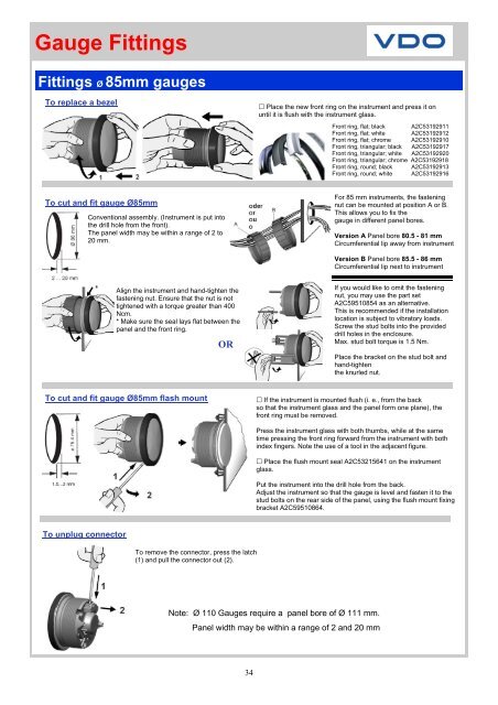
Gauge Fittings<br />
Fittings Ø 85mm gauges<br />
To replace a bezel<br />
Place the new front ring on the instrument and press it on<br />
until it is flush with the instrument glass.<br />
Front ring, flat; black A2C53192911<br />
Front ring, flat; white A2C53192912<br />
Front ring, flat; chrome A2C53192910<br />
Front ring, triangular; black A2C53192917<br />
Front ring, triangular; white A2C53192920<br />
Front ring, triangular; chrome A2C53192918<br />
Front ring, round; black A2C53192913<br />
Front ring, round; white A2C53192916<br />
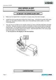
To cut and fit gauge Ø85mm<br />
Conventional assembly. (Instrument is put into<br />
the drill hole from the front).<br />
The panel width may be within a range of 2 to<br />
20 mm.<br />
For 85 mm instruments, the fastening<br />
nut can be mounted at position A or B.<br />
This allows you to fix the<br />
gauge in different panel bores.<br />
Version A Panel bore 80.5 - 81 mm<br />
Circumferential lip away from instrument<br />
Version B Panel bore 85.5 - 86 mm<br />
Circumferential lip next to instrument<br />
Align the instrument and hand-tighten the<br />
fastening nut. Ensure that the nut is not<br />
tightened with a torque greater than 400<br />
Ncm.<br />
* Make sure the seal lays flat between the<br />
panel and the front ring.<br />
OR<br />
If you would like to omit the fastening<br />
nut, you may use the part set<br />
A2C59510854 as an alternative.<br />
This is recommended if the installation<br />
location is subject to vibratory loads.<br />
Screw the stud bolts into the provided<br />
drill holes in the enclosure.<br />
Max. stud bolt torque is 1.5 Nm.<br />
Place the bracket on the stud bolt and<br />
hand-tighten<br />
the knurled nut.<br />
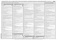
To cut and fit gauge Ø85mm flash mount<br />
If the instrument is mounted flush (i. e., from the back<br />
so that the instrument glass and the panel form one plane), the<br />
front ring must be removed.<br />
Press the instrument glass with both thumbs, while at the same<br />
time pressing the front ring forward from the instrument with both<br />
index fingers. Note the use of a tool in the adjacent figure.<br />
Place the flush mount seal A2C53215641 on the instrument<br />
glass.<br />
Put the instrument into the drill hole from the back.<br />
Adjust the instrument so that the gauge is level and fasten it to the<br />
stud bolts on the rear side of the panel, using the flush mount fixing<br />
bracket A2C59510864.<br />
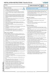
To unplug connector<br />
To remove the connector, press the latch<br />
(1) and pull the connector out (2).<br />
Note: Ø 110 Gauges require a panel bore of Ø 111 mm.<br />
Panel width may be within a range of 2 and 20 mm<br />
34