Harmony Optimization Design of Switched Reluctance Motor ... - inass
Harmony Optimization Design of Switched Reluctance Motor ... - inass
Harmony Optimization Design of Switched Reluctance Motor ... - inass

You also want an ePaper? Increase the reach of your titles
YUMPU automatically turns print PDFs into web optimized ePapers that Google loves.
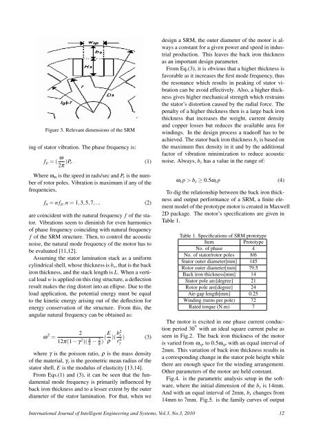
Figure 3. Relevant dimensions <strong>of</strong> the SRM<br />
ing <strong>of</strong> stator vibration. The phase frequency is:<br />
f p = ( ω 2π )P r (1)<br />
Where ω m is the speed in rads/sec and P r is the number<br />
<strong>of</strong> rotor poles. Vibration is maximum if any <strong>of</strong> the<br />
frequencies,<br />
f n = n f p ,n = 1,3,5,7,... (2)<br />
are coincident with the natural frequency f <strong>of</strong> the stator.<br />
Vibrations seem to diminish for even harmonics<br />
<strong>of</strong> phase frequency coinciding with natural frequency<br />
f <strong>of</strong> the SRM structure. Then, to control the acoustic<br />
noise, the natural mode frequency <strong>of</strong> the motor has to<br />
be evaluated [11,12].<br />
Assuming the stator lamination stack as a uniform<br />
cylindrical shell, whose thickness is b s , that is the back<br />
iron thickness, and the stack length is L. When a vertical<br />
load w is applied on this ring structure, a deflection<br />
result makes the ring distort into an ellipse. Due to the<br />
load application, the potential energy must be equal<br />
to the kinetic energy arising out <strong>of</strong> the deflection for<br />
energy conservation <strong>of</strong> the structure. From this, the<br />
angular natural frequency can be obtained as:<br />
ω 2 =<br />
2<br />
12π(1 − γ 2 )( π 4 − 2 π )(E ρ )(b2 s<br />
ry<br />
4 ) (3)<br />
where γ is the poisson ratio, ρ is the mass density<br />
<strong>of</strong> the material, γ y is the geometric mean radius <strong>of</strong> the<br />
stator shell, E is the modulus <strong>of</strong> elasticity [13,14].<br />
From Eqs.(1) and (3), it can be seen that the fundamental<br />
mode frequency is primarily influenced by<br />
back iron thickness and to a lesser extent by the outer<br />
diameter <strong>of</strong> the stator lamination. For that, when we<br />
design a SRM, the outer diameter <strong>of</strong> the motor is always<br />
a constant for a given power and speed in industrial<br />
production. This leaves the back iron thickness<br />
as an important design parameter.<br />
From Eq.(3), it is obvious that a higher thickness is<br />
favorable as it increases the first mode frequency, thus<br />
the resonance which results in peaking <strong>of</strong> stator vibration<br />
can be avoid effectively. Also, a higher thickness<br />
gives higher mechanical strength which restrains<br />
the stator’s distortion caused by the radial force. The<br />
penalty <strong>of</strong> a higher thickness then is a large back iron<br />
thickness that increases the weight, current density<br />
and copper losses but reduces the available area for<br />
windings. In the design process a trade<strong>of</strong>f has to be<br />
achieved. The stator back iron thickness b s is based on<br />
the maximum flux density in it and by the additional<br />
factor <strong>of</strong> vibration minimization to reduce acoustic<br />
noise. Always, b s has a value in the range <strong>of</strong>:<br />
ω s p > b s ≥ 0.5ω s p (4)<br />
To dig the relationship between the back iron thickness<br />
and output performance <strong>of</strong> a SRM, a finite element<br />
model <strong>of</strong> the prototype motor is created in Maxwell<br />
2D package. The motor’s specifications are given in<br />
Table 1.<br />
Table 1. Specifications <strong>of</strong> SRM prototype<br />
Item<br />
Prototype<br />
No. <strong>of</strong> phase 4<br />
No. <strong>of</strong> stator/rotor poles 8/6<br />
Stator outer diameter[mm] 145<br />
Rotor outer diameter[mm] 79.5<br />
Back iron thickness[mm] 14<br />
Stator pole arc[degree] 21<br />
Rotor pole are[degree] 24<br />
Air-gap length[mm] 0.25<br />
Winding (turns per pole) 72<br />
Rated torque (N.m) 7<br />
The motor is excited in one phase current conduction<br />
period 30 o with an ideal square current pulse as<br />
seen in Fig.2. The back iron thickness <strong>of</strong> the motor<br />
is varied from ω sp to 0.5ω sp with an equal interval <strong>of</strong><br />
2mm. This variation <strong>of</strong> back iron thickness results in<br />
a corresponding change in the stator pole height while<br />
there are enough space for the winding arrangement.<br />
Other parameters <strong>of</strong> the motor are held constant.<br />
Fig.4. is the parametric analysis setup in the s<strong>of</strong>tware,<br />
where the initial dimension <strong>of</strong> the b s is 14mm.<br />
And with an equal interval <strong>of</strong> 2mm, b s changes from<br />
14mm to 7mm. Fig.5. is the family curves <strong>of</strong> output<br />
International Journal <strong>of</strong> Intelligent Engineering and Systems, Vol.3, No.3, 2010 12