Harmony Optimization Design of Switched Reluctance Motor ... - inass
Harmony Optimization Design of Switched Reluctance Motor ... - inass
Harmony Optimization Design of Switched Reluctance Motor ... - inass

You also want an ePaper? Increase the reach of your titles
YUMPU automatically turns print PDFs into web optimized ePapers that Google loves.
air gap length. The static torque rises from 8.2N.m<br />
to 10.8N.m when air gap decreases from 0.5mm to<br />
0.25mm. In this case, it is necessary to make a trade<strong>of</strong>f<br />
according to the practical needs.<br />
3. <strong>Harmony</strong> optimization <strong>of</strong> physical design<br />
and control strategy <strong>of</strong> SRM<br />
Conventional control category <strong>of</strong> the SRM is either<br />
the single phase excited mode or the double phase excited<br />
mode under either the PWM operations or current<br />
limited control [18]. The double phase excited<br />
mode is always used in the odd phase circuit. Comparing<br />
with the single phase excited mode, the advantage<br />
<strong>of</strong> the double phase excited mode can make<br />
a significant improvement in torque production and a<br />
reduction in torque ripple to the motor. But considering<br />
the commutation freewheeling <strong>of</strong> current in the<br />
windings, part <strong>of</strong> the electrifying windings produce<br />
a negative torque, thus the complexity <strong>of</strong> controlling<br />
loops increases [19][20]. Besides, as the rotor poles<br />
rotate to the aligned position, the high flux density in<br />
the iron will bring a significant impact on the motor:<br />
increase the motor losses and reduce the efficiency.<br />
Here, an improved double excited mode is presented<br />
which can be applied to any type <strong>of</strong> the SRM, that is,<br />
a mix-excited mode.<br />
It is known that vibration is much nearer to the aligned<br />
position comparing with the unaligned position. Turning<br />
<strong>of</strong>f before full alignment reduces vibrations. And<br />
by commutating the current before alignment, the deeply<br />
saturated stator yoke is relieved magnetically. It’s better<br />
to make a turn-<strong>of</strong>f before full alignment under double<br />
phase excited working mode.<br />
Based on the analysis in the previous section, the<br />
choice <strong>of</strong> appropriate back iron thickness and air gap<br />
with a good switching point under double phase excited<br />
working mode can extend the flat torque period<br />
and reduce the core loss. A four-phased 8/6 SRM with<br />
optimized structure working under different control<br />
mode is simulated for harmony optimization. The results<br />
<strong>of</strong> the motor’s output performance are compared<br />
in Fig. 8, Fig. 9 and Fig. 10.<br />
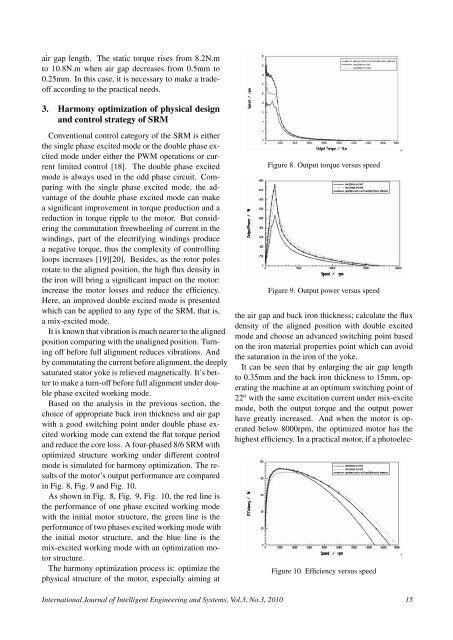
As shown in Fig. 8, Fig. 9, Fig. 10, the red line is<br />
the performance <strong>of</strong> one phase excited working mode<br />
with the initial motor structure, the green line is the<br />
performance <strong>of</strong> two phases excited working mode with<br />
the initial motor structure, and the blue line is the<br />
mix-excited working mode with an optimization motor<br />
structure.<br />
The harmony optimization process is: optimize the<br />
physical structure <strong>of</strong> the motor, especially aiming at<br />
Figure 8. Output torque versus speed<br />
Figure 9. Output power versus speed<br />
the air gap and back iron thickness; calculate the flux<br />
density <strong>of</strong> the aligned position with double excited<br />
mode and choose an advanced switching point based<br />
on the iron material properties point which can avoid<br />
the saturation in the iron <strong>of</strong> the yoke.<br />
It can be seen that by enlarging the air gap length<br />
to 0.35mm and the back iron thickness to 15mm, operating<br />
the machine at an optimum switching point <strong>of</strong><br />
22 o with the same excitation current under mix-excite<br />
mode, both the output torque and the output power<br />
have greatly increased. And when the motor is operated<br />
below 8000rpm, the optimized motor has the<br />
highest efficiency. In a practical motor, if a photoelec-<br />
Figure 10. Efficiency versus speed<br />
International Journal <strong>of</strong> Intelligent Engineering and Systems, Vol.3, No.3, 2010 15