Harmony Optimization Design of Switched Reluctance Motor ... - inass
Harmony Optimization Design of Switched Reluctance Motor ... - inass
Harmony Optimization Design of Switched Reluctance Motor ... - inass

You also want an ePaper? Increase the reach of your titles
YUMPU automatically turns print PDFs into web optimized ePapers that Google loves.
Then the tangential torque is obtained as:<br />
T e = dW m<br />
dθ = l g Φ 2<br />
2µ 0 Lr θ 2 = l grL<br />
B 2<br />
2µ<br />
g(θ,l g ,i) (12)<br />
0<br />
Therefore, the tangential force is obtained by dividing<br />
the tangential torque by the radius <strong>of</strong> the rotor<br />
pole, yielding:<br />
F t = T e<br />
r = l gL<br />
2µ 0<br />
B 2 g(θ,l g ,i) (13)<br />
The radial force in the direction <strong>of</strong> the air gap is obtained<br />
from considering the incremental field energy<br />
with respect to the air gap and the incremental mechanical<br />
energy as:<br />
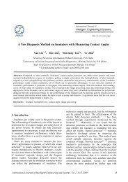
Figure 6. Radial forces versus rotor position curves<br />
dW m = − 1 Φ 2<br />
2µ 0 rL θ dl g (14)<br />
and the radial force is :<br />
F n = dW m<br />
dl g<br />
= − 1<br />
2µ 0<br />
. Φ θ = −rµ 0Lθ.T 2 ph .i2<br />
2l 2 g<br />
Similarly, the lateral force can be derived as:<br />
(15)<br />
F y = l grθ<br />
2µ 0<br />
B 2 g(θ,l g ,i) (16)<br />
From the equations above, it can be stated that lateral<br />
force and tangential force are <strong>of</strong> similar magnitude<br />
but the radial force is not. From Eqs.(13) and<br />
(15), the ratio between the radial force and tangential<br />
force is:<br />
F n<br />
F t<br />
= − rθ<br />
l g<br />
(17)<br />
The rotor angle can be assumed to be equal to the<br />
one-phase conduction angle which in terms <strong>of</strong> the rotor<br />
and stator poles is given as:<br />
θ = 4π<br />
P s P r<br />
(18)<br />
where P S and P r are the number <strong>of</strong> stator and rotor<br />
poles.<br />
From the analytical expression, an obvious way to<br />
reduce noise would be to reduce the flux density by<br />
enlarging the air gap. Also a larger air gap is preferred<br />
from the manufacturing points <strong>of</strong> view. It is<br />
clear that a large air gap length is preferred in a reasonable<br />
range.<br />
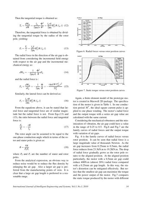
Figure 7. Static torque versus rotor position curves<br />
Again, a finite element model <strong>of</strong> the prototype motor<br />
is created in Maxwell 2D package. The specification<br />
<strong>of</strong> the motor is given in Table 1. In one conduction<br />
period 30 o , the ideal square current pulse is applied<br />
to one phase winding. The motor’s radial force<br />
and the output torque with a series air gap value are<br />
calculated with the same current.<br />
Considering the mechanical robustness and the minimization<br />
<strong>of</strong> vibration, the air gap could have a value<br />
in the range <strong>of</strong> 0.25 to 0.5. Fig.6 and Fig.7 are the<br />
family curves <strong>of</strong> radial forces and the output torque<br />
with variation <strong>of</strong> air gaps.<br />
Fig. 6 is the family curves <strong>of</strong> radial forces versus<br />
rotor position. It can be seen that radial force is a<br />
large magnitude value <strong>of</strong> thousands Newton. As the<br />
air gap increases from 0.25mm to 0.5mm, the radial<br />
force reduces from 23.3kN.m to 19.2KN.m. The drop<br />
<strong>of</strong> radial force gradually grows as the rotor pole rotates<br />
to the aligned position. At the aligned position<br />
particularly, the motor with a 0.5mm air gap could<br />
reduce 400N.m (almost 20%) radial force compared<br />
with a 0.25mm air gap length. In this way, the stator’s<br />
distortion can be mitigated effectively. But notice<br />
that the smallest air gap can maximize the torque<br />
and the power output <strong>of</strong> the motor. Fig.7 compares<br />
the static torque produced by the motor with different<br />
International Journal <strong>of</strong> Intelligent Engineering and Systems, Vol.3, No.3, 2010 14