Harmony Optimization Design of Switched Reluctance Motor ... - inass
Harmony Optimization Design of Switched Reluctance Motor ... - inass
Harmony Optimization Design of Switched Reluctance Motor ... - inass

Create successful ePaper yourself
Turn your PDF publications into a flip-book with our unique Google optimized e-Paper software.
. Let r be the outer radius <strong>of</strong> the rotor, L be the stack<br />
length or iron length in the z direction, T ph be the<br />
number <strong>of</strong> turns in one phase <strong>of</strong> the machine, i be<br />
the current in the winding, Hg be the magnetic field<br />
strength, Φ be the flux, and µ 0 be the permeability <strong>of</strong><br />
air, then the variables are derived as:<br />
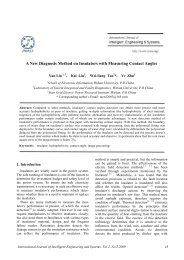
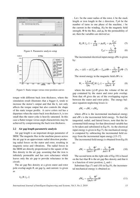
Figure 4. Parametric analysis setup<br />
B g (θ,l g ,i) =<br />
Φ<br />
Lrθ = µ T ph i<br />
0H g = µ 0 (5)<br />
l g<br />
T ph i =<br />
l g Φ<br />
µ 0 Lr θ<br />
(6)<br />
The incremental electrical input energy dWe is given<br />
by:<br />
dw e = idλ = id(T ph Φ) = T ph idΦ =<br />
l g Φ<br />
dΦ (7)<br />
µ 0 Lr θ<br />
The stored energy in the magnetic field dWs is<br />
W s = l gLrθ<br />
B 2<br />
2µ<br />
g(θ,l g .i) = l g Φ 2<br />
0 2µ 0 rL θ<br />
(8)<br />
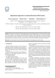
Figure 5. Static torque versus rotor position curves<br />
torque with different back iron thickness, where the<br />
simulation result illustrates that a bigger b s tends to<br />
increase the motor’s output and that the b s not only<br />
affects the torque output but also controls the shape<br />
<strong>of</strong> the static torque pr<strong>of</strong>ile. A curve colors red has a<br />
departure when the stator back iron thickness b s is too<br />
small thus the stator yoke is heavily saturated. In this<br />
case a flatter torque versus angle characteristic may be<br />
achieved by compromising the back iron thickness.<br />
2.2 Air gap length parametric analysis<br />
Air gap length is an important design parameter <strong>of</strong><br />
SRM. The magnetic flux in the machine passes across<br />
the air gap in an approximate radial direction producing<br />
radial forces on the stator and rotor, resulting in<br />
magnetic noise and vibrations. The radial forces in<br />
the SRM are directly proportional to the square <strong>of</strong> the<br />
flux density in the air gap, assuming that the iron is<br />
infinitely permeable and has zero reluctance which<br />
leaves only the air gap to provide reluctance in the<br />
circuit.<br />
The air gap flux density at a given stator and rotor<br />
pole overlap angle θ, air gap lg, and current i is given<br />
as<br />
b g (θ,l g ,i)<br />
where the term l g Lrθ gives the volume <strong>of</strong> the air<br />
gap contained by the stator and rotor pole overlap.<br />
Note that rθ gives the arc <strong>of</strong> the overlapping region<br />
between the stator and rotor poles. The energy balance<br />
equation neglecting losses is:<br />
dW e = dW s + dW m (9)<br />
where dWm is the incremental mechanical energy<br />
and dWs is the incremental field energy. To find the<br />
tangential, radial, and lateral forces, note that the incremental<br />
field energy for that directional variable has<br />
to be taken and substituted in Eq.(9). As the electrical<br />
input energy is given in Eq.(7), the mechanical energy<br />
is computed by subtracting the incremental field energy<br />
from the incremental input energy [15-17].<br />
The incremental field energy is obtained from Eq.(8)<br />
as:<br />
dW s =<br />
l g Φ 2<br />
2µ 0 Lr θ 2 dθ +<br />
l g<br />
µ 0 Lr<br />
Φ<br />
dΦ (10)<br />
θ<br />
The second term on the right side <strong>of</strong> Eq.(10) is based<br />
on the fact that Φ is the air gap flux density and that it<br />
is a function <strong>of</strong> rotor position, l g and i.<br />
Substitute Eqs.(7) and (10) in Eq.(9), the incremental<br />
mechanical energy is obtained as:<br />
dW m =<br />
l g Φ 2<br />
dθ (11)<br />
2µ 0 Lr θ 2<br />
International Journal <strong>of</strong> Intelligent Engineering and Systems, Vol.3, No.3, 2010 13