Reactor Core Structure of Qinshan Phase III CANDU Nuclear Power ...
Reactor Core Structure of Qinshan Phase III CANDU Nuclear Power ...
Reactor Core Structure of Qinshan Phase III CANDU Nuclear Power ...

You also want an ePaper? Increase the reach of your titles
YUMPU automatically turns print PDFs into web optimized ePapers that Google loves.
Paper # 3. 99-03-19<br />
Description <strong>of</strong> the <strong>Reactor</strong> <strong>Core</strong> <strong>of</strong> the Third <strong>Qinshan</strong> <strong>Nuclear</strong> <strong>Power</strong><br />
Plant (TQNPP)<br />
by<br />
Qiu Suizheng* and Norman C. Johnston**<br />
*Xi’an Jiaotong University<br />
**Atomic Energy <strong>of</strong> Canada Limited<br />
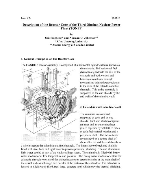
1. General Description <strong>of</strong> The <strong>Reactor</strong> <strong>Core</strong><br />
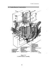
The <strong>CANDU</strong> 6 reactor assembly is comprised <strong>of</strong> a horizontal cylindrical tank known as<br />
the calandria, 380 horizontal fuel<br />
channels aligned with the axis <strong>of</strong> the<br />
calandria and both vertical and<br />
horizontal reactivity control<br />
mechanisms oriented perpendicular<br />
to the axes <strong>of</strong> the calandria and fuel<br />
channels. This entire assembly is<br />
supported at the end shields by the<br />
end walls <strong>of</strong> the calandria vault<br />
2. Calandria and Calandria Vault<br />
The calandria is closed and<br />
supported at each end by end<br />
shields. Each end shield comprises<br />
an inner and an outer tubesheet<br />
joined together by 380 lattice tubes<br />
at each fuel channel location and a<br />
peripheral shell. The lattice tubes<br />
are arranged on a square pitch <strong>of</strong><br />
about 28.6 cm and the end shields as<br />
a whole support the calandria and fuel channels. The inner space <strong>of</strong> each end shield is<br />
filled with steel balls and light water to provide personnel shielding. The end shields are<br />
light water cooled as part <strong>of</strong> the vault cooling system. The calandria is filled with heavy<br />
water moderator at low temperature and pressure. The heavy water moderator enters the<br />
calandria through two sets <strong>of</strong> fan shaped nozzles on opposites sides <strong>of</strong> the main shell <strong>of</strong><br />
the vessel and exits through two nozzles at the bottom <strong>of</strong> the calandria. The calandria is<br />
located in a light water filled, steel lined, concrete vault which provides thermal shielding.
Though part <strong>of</strong> the Class 3 moderator system, the calandria is optionally manufactured to<br />
the requirements <strong>of</strong> the ASME Boiler and Pressure Vessel Code, Section <strong>III</strong>, “Rules for<br />
Construction <strong>of</strong> <strong>Nuclear</strong> <strong>Power</strong> Plant<br />
Components”, Subsection NC,<br />
“Rules for Class 2 Components”. It<br />
is fabricated from stainless steel and<br />
has a main shell diameter <strong>of</strong> 7.65 m,<br />
an inside core length <strong>of</strong> 5.94 m and a<br />
shell thickness <strong>of</strong> 28.6 mm.<br />
reactivity control units.<br />
The calandria vault comprises a<br />
rectangular reinforced concrete<br />
structure, closed at the top by the<br />
reactivity mechanism deck. The<br />
reactivity mechanism deck supports<br />
the upper ends <strong>of</strong> the reactivity<br />
control units, their mechanisms,<br />
shielding, and connecting tubes and<br />
cables. The reactivity mechanism<br />
deck is a concrete-filled steel box<br />
structure with penetrations for the<br />
Fuel Channels<br />
There are 380 fuel channels that comprise the in-core part <strong>of</strong> the primary heat transport<br />
system. Each fuel channel locates and supports 12 fuel bundles in the reactor core. They<br />
allow the primary heat transport fluid to pass through, removing the heat generated in the<br />
fuel and permit the fuelling machines to refuel while the reactor is operating at full power.<br />
The fuel channel assembly includes a zirconium niobium alloy pressure tube, a zirconium<br />
alloy calandria tube, stainless steel end fittings at each end, and four spacers which<br />
maintain separation <strong>of</strong> the pressure tube and the calandria tube. Each pressure tube is<br />
thermally insulated from the cool, low pressure moderator, by the CO 2 filled gas annulus<br />
formed between the outside <strong>of</strong> the pressure tube and the inside <strong>of</strong> the concentric calandria<br />
tube. The zirconium alloy calandria tube is joined at each end to one <strong>of</strong> the stainless steel<br />
calandria end shields by means <strong>of</strong> a sandwich type mechanical rolled joint. The calandria<br />
tube is an integral part <strong>of</strong> the calandria vessel pressure boundary.<br />
Each end fitting incorporates a feeder connection through which heavy water coolant<br />
enters and leaves the fuel channel. Pressurized heavy water coolant flows around and<br />
through the fuel bundles in the fuel channel and removes the heat generated in the fuel by
nuclear fission. Coolant flow through adjacent channels in the reactor is in opposite<br />
directions. During on-power refuelling, the fuelling machines first make a leak tight<br />
connection to both ends <strong>of</strong> a channel, then gains access by removing the closure plugs and<br />
shield plugs from both end fittings <strong>of</strong> the channel to be refuelled.<br />
The pressure tube and end<br />
fittings are manufactured to<br />
the requirements <strong>of</strong> the<br />
ASME Boiler and Pressure<br />
Vessel Code, Section <strong>III</strong>,<br />
“Rules for Construction <strong>of</strong><br />
<strong>Nuclear</strong> <strong>Power</strong> Plant<br />
Components”, Subsection<br />
NB, “Rules for Class 1<br />
Components” and form part<br />
<strong>of</strong> the primary heat<br />
transport system. The<br />
pressure tube has an inside<br />
diameter <strong>of</strong> about 104 mm, a<br />
wall thickness <strong>of</strong> about 4<br />
mm and a length <strong>of</strong> about 6.3<br />
m. The dissimilar metals <strong>of</strong><br />
the pressure tube and end fittings are joined by means <strong>of</strong> a high integrity, roll-expanded<br />
joint that has been qualified for in-reactor use by an extensive program.<br />
The Third <strong>Qinshan</strong> <strong>Nuclear</strong> <strong>Power</strong> Plant has a design life <strong>of</strong> 40 years at an average<br />
capacity <strong>of</strong> 85%. This is readily achieved, in part, because the design <strong>of</strong> the fuel channel<br />
permits their replacement. The pressure tubes have a design life <strong>of</strong> 25 years at an average<br />
capacity factor <strong>of</strong> 85%.<br />
Reactivity Control Units<br />
General<br />
The reactivity control units form the in-core sensing and actuating portions <strong>of</strong> the reactor<br />
regulating system and the two reactor shutdown systems, shutdown system 1 and<br />
shutdown system 2. Since they are physically parts <strong>of</strong> the reactor assembly, they share<br />
many common bases for their mechanical design. The following sections describe these<br />
common aspects <strong>of</strong> the reactivity control units.<br />
All reactivity control units perform one <strong>of</strong> three functions for their respective system(s):
1. Those which measure fission power levels,<br />
2. Those which regulate power levels and,<br />
3. Those which shutdown the reactor.<br />
In <strong>CANDU</strong> reactors, emergency shutdown devices and systems are entirely independent<br />
<strong>of</strong> those used for reactor power regulation. Furthermore, two independent and diverse<br />
shutdown systems are provided, each <strong>of</strong> which has full shutdown capability independent<br />
<strong>of</strong> the other.<br />
The following is a description <strong>of</strong> each reactivity control unit, its function and the<br />
system(s) in which it is installed. Further there is an initial description <strong>of</strong> three<br />
mechanical elements common to many <strong>of</strong> the reactivity control units, namely the<br />
reactivity mechanism deck, the thimbles and the guide tubes:<br />
Reactivity Mechanism Deck<br />
The reactivity mechanism deck is a concrete-filled, carbon steel box structure, internally<br />
stiffened with webs that are located above the calandria in a space created in the top <strong>of</strong><br />
the calandria vault. The concrete is not needed for strength, but for local radiation<br />
shielding during flasking. The steel structure incorporates the penetration inserts for the<br />
vertical reactivity control units. Each insert contains an accurately located bearing to<br />
support the reactivity control unit thimble. A heavy tread plate is supported above the<br />
structure to provide a<br />
protected free space<br />
for cabling and<br />
services to the control<br />
units, while leaving an<br />
uncluttered walkway<br />
above for maintenance<br />
access. The tread<br />
plate also provides<br />
added local shielding<br />
during flasking<br />
operations to remove<br />
a device from the<br />
reactor core.<br />
The deck structure is secured in a seat in the top <strong>of</strong> the vault through a wide, flexible, seal<br />
strip to accommodate thermal expansion, yet be sufficiently stiff to behave as a rigid<br />
coupling under seismic conditions.
Thimbles<br />
The vertical thimbles extend from the top <strong>of</strong> the calandria up through the reactivity<br />
mechanism deck and are surrounded by the vault light water. They are welded in precise<br />
locations to the calandria shell nozzles and are vertically free to slide in bearings<br />
positioning them in the reactivity mechanism deck. Metal bellows are welded to the<br />
thimbles and deck penetrations to maintain a seal while permitting free vertical movement<br />
to accommodate differential thermal expansion between the thimbles and deck.<br />
The horizontal thimbles extend from the shield wall through the vault wall to the calandria<br />
nozzles. Like their vertical counterparts, they are supported by bearings in the wall<br />
penetrations and are sealed by flexible metallic bellows. Each horizontal thimble also<br />
carries a second bellows, which connects to<br />
the liquid injection shutdown unit injection<br />
tube or horizontal flux detector assembly<br />
guide tube, acting both as a heavy water<br />
seal and a tensioner.<br />
Guide Tubes<br />
Each guide tube assembly comprises a<br />
zircaloy tube that passes through the<br />
moderator in the core and a stainless steel<br />
out-<strong>of</strong>-core section. The out-<strong>of</strong>-core part is<br />
called a guide tube extension.<br />
The guide tubes for the shut<strong>of</strong>f, mechanical<br />
control absorber and adjuster units have<br />
many large, close-pitched perforations<br />
along their length. This minimizes the<br />
amount <strong>of</strong> neutron absorbing material and also precludes voids in the moderator. The<br />
guide tubes are each seated at the top in precisely located conical seats in the bottom end<br />
fittings <strong>of</strong> the thimbles, which are welded to the nozzles at the top <strong>of</strong> the calandria shell.<br />
Their extensions are installed separately, and seat in the top fitting <strong>of</strong> the guide tubes.<br />
The guide tube for the vertical flux detector unit is not perforated, but is vented to the<br />
moderator through small top and bottom holes. The guide tube <strong>of</strong> the horizontal flux<br />
detector units is not perforated or vented, but is a gas filled pressure-retaining tube. Both<br />
designs include a permanent mechanical joint between their two sections.<br />
All vertical guide tubes are secured at their bottom ends by locators on the bottom <strong>of</strong> the<br />
calandria shell. The locators are adjustable laterally during initial installation, to permit
accurate alignment <strong>of</strong> the guide tubes' bottom ends. All guide tubes are tensioned flexibly<br />
to reduce the amplitude <strong>of</strong> vibrations induced either by water turbulence or possible<br />
earthquake, while also permitting differential thermal expansion between the guide tubes<br />
and the calandria. Vertical flux detector guide tubes are tensioned by a spring at the top <strong>of</strong><br />
the extension. Horizontal flux detector guide tubes (and liquid injection shutdown unit<br />
nozzle tubes) are tensioned by metal bellows on the ends <strong>of</strong> their thimbles, outside the<br />
vault wall. Guide tubes for all other reactivity control units are tensioned by coil springs<br />
in the bottoms <strong>of</strong> the tubes, acting on the couplings, screwed into the locators.<br />
Shut<strong>of</strong>f Units<br />
The 28 shut<strong>of</strong>f units comprise the absorber / actuator portion <strong>of</strong> shutdown system<br />
number 1. It is the primary method <strong>of</strong> quickly shutting down the reactor when certain<br />
parameters enter an unacceptable range. This shutdown system senses the requirement<br />
for a reactor trip and de-energizes<br />
the direct current clutches to<br />
release the absorber element<br />
portion <strong>of</strong> the shut<strong>of</strong>f units,<br />
allowing them to drop between<br />
columns <strong>of</strong> fuel channels, into the<br />
moderator. Each shutdown rod is<br />
equipped with a spring that<br />
provides an initial acceleration.<br />
Each shut<strong>of</strong>f unit comprises a<br />
stainless steel-sheathed tubular<br />
cadmium shut<strong>of</strong>f rod, a vertical<br />
guide tube and guide tube<br />
extension, a drive mechanism and<br />
accelerator spring, a thimble, shield<br />
plugs and deck penetration<br />
components, and rod ready<br />
indicator. Each shut<strong>of</strong>f rod is<br />
suspended from a stainless steel<br />
wire rope wound onto the sheave<br />
<strong>of</strong> its drive mechanism.<br />
The drive mechanism is an electric<br />
motor powered winch that includes an electro-magnetic clutch to couple the sheave shaft<br />
to its gear train. De-energization <strong>of</strong> the clutch permits the sheave to rotate freely, under<br />
the weight <strong>of</strong> the rod. The mechanism is bolted and sealed on the top <strong>of</strong> the thimble<br />
directly above the reactivity mechanism deck. A small acceleration is imparted to the rod
y the compressed accelerator spring over the first 0.6 m <strong>of</strong> travel. The fall <strong>of</strong> the rod is<br />
arrested at the end <strong>of</strong> its travel by a rotary hydraulic damper within the drive mechanism.<br />
When the clutch is energized by clearance <strong>of</strong> the trip signal, the motor raises the rod. The<br />
vertical position <strong>of</strong> the rod is measured by a rotary electrical potentiometer on its sheave<br />
shaft.<br />
The sheave shaft is permanently coupled to the damper through the position limiter<br />
device. The damper vane stops against a fixed pad in the housing at each end <strong>of</strong> its travel,<br />
and thus provides the mechanical end <strong>of</strong> travel stops for the shaft rotation. When the rod<br />
is driven up or down, the motion is stopped before the end <strong>of</strong> mechanical travel is reached<br />
by the motor being shut <strong>of</strong>f by the control system via the position sensing circuit run<br />
from the potentiometer output. A second position sensor, the "rod ready" indicator,<br />
directly monitors the presence <strong>of</strong> the rod in the up position, to verify it is "ready" for<br />
use. It comprises a set <strong>of</strong> magnetic switches mounted in a well in the shield plug, actuated<br />
by a permanent magnet mounted in the top <strong>of</strong> the shut<strong>of</strong>f rod.<br />
Mechanical Control Absorber Units<br />
The four mechanical control units form part <strong>of</strong> the absorber / actuator component <strong>of</strong> the<br />
reactor regulating system. The mechanical control absorbers, mounted above the reactor,<br />
can be driven in or out <strong>of</strong> the core at variable speeds, or dropped by gravity into the core,<br />
between columns <strong>of</strong> fuel channels, by releasing a clutch. These absorbers are normally<br />
parked out <strong>of</strong> the core; they are driven in to supplement the negative reactivity from the<br />
light water zone control absorbers, or are dropped to effect a fast reduction in reactor<br />
power (stepback). When inserted, the mechanical control absorbers also help to prevent<br />
the reactor from going critical when the shut<strong>of</strong>f rods <strong>of</strong> shutdown system 1 are<br />
withdrawn, and are interlocked, in this inserted position, until the shutdown system<br />
number 1 is energized and available.<br />
The mechanical control absorber units are essentially the same as the shut<strong>of</strong>f units, except<br />
that the shut<strong>of</strong>f unit accelerator spring and rod ready indicator are not incorporated, and<br />
the control absorber rod is provided with an orifice to reduce the insertion velocity for a<br />
free drop insertion.<br />
Adjusters<br />
A <strong>CANDU</strong> 6 reactor has 21 vertically mounted adjuster rods, that are normally fully<br />
inserted between columns <strong>of</strong> fuel channels as part <strong>of</strong> the reactor regulating system, and are<br />
used for flux shaping. Removal <strong>of</strong> adjusters from the core provides positive reactivity to<br />
compensate for xenon buildup following large power reductions, or in the event that the<br />
on-power refuelling system is temporarily unavailable. The adjusters are capable <strong>of</strong> being
driven in and out <strong>of</strong> the reactor core at variable speed to provide reactivity control. The<br />
adjusters are normally driven in banks, the largest bank containing five rods. Adjuster<br />
rods are usually fabricated from stainless steel. In some <strong>CANDU</strong> plants the adjuster rods<br />
contain cobalt, and are used to produce cobalt 60 for medical and industrial purposes.<br />
Each adjuster unit comprises an adjuster rod, a vertical guide tube and guide tube<br />
extension, thimble and shield plugs, and a drive mechanism. The adjuster rod consists <strong>of</strong> a<br />
thin-walled stainless steel tube with a central stainless steel shim rod. The absorber<br />
element and its shim center rod are <strong>of</strong> stepped thicknesses along their lengths to provide<br />
required neutron absorption characteristics. Each rod is suspended by a stainless steel<br />
wire rope from its mechanism. The vertical location <strong>of</strong> the rod is indicated by a<br />
potentiometer coupled to the drive mechanism sheave shaft.<br />
The adjuster drive mechanism is a permanently coupled, electric motor powered, geared<br />
winch. The high reduction ratio in the gearing makes it self-locking. The sheave is<br />
enclosed in a pressure vessel housing whose interior is open to the moderator cover gas in<br />
the thimble. Its shaft passes through a carbon / ceramic face seal to the non-pressurized<br />
gear case. The drive housing is bolted and sealed to the thimble top.<br />
The movement <strong>of</strong> the rods as they are raised or lowered is guided within perforated guide<br />
tubes within the calandria, and in plain guide tube extensions above.<br />
Liquid Injection Shutdown Units<br />
The liquid injection shutdown nozzles are the in-core components <strong>of</strong> shutdown system<br />
number 2. This is an alternate method <strong>of</strong> quickly shutting down the reactor by the rapid<br />
injection <strong>of</strong> poison (concentrated gadolinium nitrate solution) into the moderator through<br />
perforated horizontal zircaloy tubes that span the calandria between rows <strong>of</strong> fuel<br />
channels. There are six poison injection nozzles in a <strong>CANDU</strong> 6 reactor. Shutdown<br />
system number 2 senses the requirement for a reactor shutdown and opens fast-acting<br />
valves located in the line between a high-pressure helium tank and the poison tanks. The<br />
released helium expels the poison solution from the tanks by acting on the polyurethane<br />
poison injection tank balls floating on the surface <strong>of</strong> the poison solution. Thus, the<br />
poison solution is forced through the injection nozzles and into the moderator. The<br />
injection ceases and the calandria is isolated from the helium when the balls reach seats in<br />
the bottom <strong>of</strong> the poison injection tanks.<br />
Each liquid injection shutdown unit comprises an in-core injection nozzle tube, an<br />
injection tube, a thimble and a calandria vault wall penetration assembly. The injection<br />
nozzles screw into the stainless steel injection tubes at their inlet ends and bayonet into<br />
locators on the opposite side <strong>of</strong> the calandria. Each nozzle is perforated by rows <strong>of</strong> small<br />
nozzle holes spaced and oriented to optimize poison dispersal in the moderator.
lon Chamber System<br />
There are a total <strong>of</strong> six ion chamber housings in a <strong>CANDU</strong> 6 reactor. Each housing<br />
contains three cavities which can accommodate an ion chamber unit, a test shutter<br />
cylinder or start-up instrumentation. Three ion chambers are employed in the reactor<br />
regulating system, for measuring neutron flux. These ion chambers are located in housings<br />
at one side <strong>of</strong> the core. In addition to one ion chamber for the reactor regulating system,<br />
each housing also contains an ion chamber and shutter for shutdown system number 1.<br />
Three similar ion chambers, mounted on the other side <strong>of</strong> the core, provide inputs to<br />
shutdown system number 2.<br />
Each ion chamber unit consists <strong>of</strong> the ion chamber housing, access tubes and vault wall<br />
penetration assembly, shield plugs, ion chamber instruments and cables, and the shutter<br />
assembly and its air connections. Brackets welded to the outside <strong>of</strong> the calandria shell are<br />
also parts <strong>of</strong> these units.<br />
Ion chamber housings do not penetrate inside the calandria, and their interior is vented to<br />
the reactor-building atmosphere outside the vault wall. The housings and the access tubes<br />
penetrating the vault wall are uniquely designed as low-pressure vessels with vault water<br />
on their exterior surface. The housing is filled with lead surrounding the instrument<br />
cavities, to absorb gamma flux and make the instruments sensitive only to neutrons.<br />
The access tubes pass through a penetration assembly in the vault side-wall. These<br />
permit direct manual installation or removal <strong>of</strong> the instruments, shutter assembly, shield<br />
plugs and electrical and air connections. They are enclosed in the vault wall penetration<br />
by a protective sleeve. A bellows maintains a light water seal while being flexible to allow<br />
for relative movement between the calandria and the vault.<br />
The shutter assembly consists <strong>of</strong> a boral cylinder mounted on a push rod which extends<br />
back through the inner shield plug segment, on bearings, to the air cylinder which is buried<br />
in the outboard segment <strong>of</strong> the shield plug. An electric switch on the rod signals the<br />
stroking position <strong>of</strong> the shutter.<br />
Self-powered In-core Flux Detectors<br />
The in-core flux detectors <strong>of</strong> the regulating system and <strong>of</strong> shutdown system number 1 are<br />
mounted vertically in the core, while those <strong>of</strong> shutdown system number 2 are mounted<br />
horizontally in the core.
Each flux detector unit consists <strong>of</strong> a flux detector assembly, a guide tube, a thimble, and<br />
penetration and seal components at either the reactivity mechanism deck or the vault wall.<br />
The flux detector assembly comprises a factory sealed capsule tube containing a number<br />
<strong>of</strong> detector elements in individual well tubes, joined to the connector housing and<br />
enclosing individual connectors and shield plugs. It is filled and sealed with pure helium at<br />
moderate pressure to ensure that the detectors obtain the maximum protection against<br />
possible corrosion. The helium also provides thermal conduction <strong>of</strong> nuclear heat from the<br />
detectors to the cool guide tube.<br />
The in-core portion <strong>of</strong> each flux detector assembly comprises a full-length capsule tube<br />
assembly, inserted into a guide tube. A cluster <strong>of</strong> twelve thin well tubes is inserted into<br />
the capsule tube. Eleven well tubes can be used to insert straight individually replaceable<br />
self-powered detector elements <strong>of</strong> varied lengths <strong>of</strong> lead wires to reach specified in-core<br />
positions; all assemblies have fewer than eleven detectors installed and vacant sites are<br />
filled with shield plugs.<br />
Each detector element comprises a central emitter wire enclosed in a sealed, thin Inconel<br />
sheath tube. A ceramic insulator separates the two conductors. Different metals are used<br />
for emitters to provide the different response characteristics. Each element is about 0.7 m<br />
long and carries an integrally connected sheathed lead wire, terminated at an individual<br />
connector inside the connector housing.<br />
The twelfth well tube normally carries a shield plug and is reserved for other possible<br />
uses.<br />
Light Water Zone Control Assemblies
Light water (H 2 O) is a neutron absorber (poison) in the heavy water cooled and<br />
moderated <strong>CANDU</strong> reactor. The liquid zone control system takes advantage <strong>of</strong> this fact<br />
to provide short-term global and spatial reactivity control and is another part <strong>of</strong> the<br />
reactor regulating system. The liquid zone control system in the reactor consists <strong>of</strong> six<br />
tubular, vertical, zone control units that span the core. Each zone control unit contains<br />
either two or three zone control compartments, providing a total <strong>of</strong> 14 zone control<br />
compartments in the reactor. The zone control units are located such that the 14 zone<br />
control compartments<br />
are distributed<br />
throughout the core,<br />
thereby dividing the<br />
core into 14 zones for<br />
the purposes <strong>of</strong> flux<br />
control. Flux (power)<br />
in each zone is<br />
controlled by the<br />
addition or removal <strong>of</strong><br />
light water to / from<br />
the liquid zone<br />
control compartment<br />
in that zone. This is<br />
accomplished by<br />
controlling the level <strong>of</strong><br />
light water in the<br />
liquid zone control<br />
compartment.<br />
The zone control unit<br />
does not have a guide<br />
tube, as it is inserted<br />
directly through the<br />
thimble into the<br />
moderator.