Physics Codes and Methods for CANDU Reactor by ... - Basic Search
Physics Codes and Methods for CANDU Reactor by ... - Basic Search
Physics Codes and Methods for CANDU Reactor by ... - Basic Search

Create successful ePaper yourself
Turn your PDF publications into a flip-book with our unique Google optimized e-Paper software.
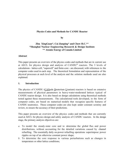
<strong>Physics</strong> <strong>Codes</strong> <strong>and</strong> <strong>Methods</strong> <strong>for</strong> <strong>CANDU</strong> <strong>Reactor</strong><strong>by</strong>Zhu XingGuan*, Cai Jianping* <strong>and</strong> Chow H.C.***Shanghai Nuclear Engineering Research & Design Institute** Atomic Energy of Canada LimitedAbstractThis paper presents an overview of the physics codes <strong>and</strong> methods that are in current useat AECL <strong>for</strong> physics design <strong>and</strong> analysis of <strong>CANDU</strong> ® reactors. The 3 levels ofcalculations - lattice-cell, “supercell” <strong>and</strong> finite-core - are discussed, with references to thecomputer codes used in each step. The theoretical <strong>for</strong>mulation <strong>and</strong> representation of thephysical processes at each level of the analysis <strong>and</strong> the solution methods used are alsoexplained.1. IntroductionThe physics of <strong>CANDU</strong> (CANada Deuterium Uranium) reactors is based on extensivemeasurements of physical parameters in heavy-water-moderated lattices typical of<strong>CANDU</strong> reactor design. It is also based on design calculations using theoretical methodstested against these measurements. The calculational tools developed, in the <strong>for</strong>m ofcomputer codes, are based on numerical models that recognize specific features of<strong>CANDU</strong> neutronics. These computer codes are also kept under constant scrutiny <strong>and</strong>review, to ensure the accuracy of their predictions.This paper presents an overview of the physics codes <strong>and</strong> methods that are currentlyused at AECL <strong>for</strong> physics design <strong>and</strong> safety analysis of <strong>CANDU</strong> reactors. In the designstage, the primary analysis objectives are:a. To model the steady-state core <strong>and</strong> to determine the global flux <strong>and</strong> powerdistributions, without accounting <strong>for</strong> the detailed variations caused <strong>by</strong> channelrefuelling. The essentially daily on-power refuelling operations superimpose powerripples on top of an otherwise constant power shape;b. To determine the core response to various perturbations such as changes intemperature or other lattice conditions;
c. To establish the configuration <strong>and</strong> neutronic characteristics of control <strong>and</strong> shutdowndevices, which will ensure that they meet their functional requirements;d. To study behaviour of the core in both slow <strong>and</strong> fast transients, such as xenontransients originating from normal operational maneuvers or postulated accidents, e.g.a large loss of coolant. The analysis of hypothetical accidents is per<strong>for</strong>med insupport of safety analyses, to characterize the reactor’s dynamic response,accounting <strong>for</strong> delayed-neutron effects <strong>and</strong> the action of the fast-acting shutdownsystems.<strong>Physics</strong> calculations are also per<strong>for</strong>med in support of normal reactor operation. Theobjectives in these specific applications are:a. To track the reactor operation history in terms of power production, channelrefuellings, fuel-bundle movements, in-core power <strong>and</strong> burnup distributions, <strong>and</strong>discharge burnup;b. To ensure that the peak channel power <strong>and</strong> bundle power comply with the licensinglimits;c. To establish the maximum channel-power peaking factor due to refuelling ripples;d. To facilitate the judicious choice of fuel channels scheduled <strong>for</strong> refuelling.There are three levels or steps of calculations in the analyses per<strong>for</strong>med to achieve theseobjectives:1. The <strong>CANDU</strong> core consists of a lattice of fuel channels arranged in a square array offixed spacing (the “lattice pitch”). Each lattice cell, consisting of a fuel bundle, thecoolant, pressure <strong>and</strong> cal<strong>and</strong>ria tubes, <strong>and</strong> moderator is there<strong>for</strong>e a basic unit inbuilding a reactor core model, with its neutronics characteristics represented <strong>by</strong> a setof “homogenized nuclear reaction cross sections” determined from lattice-cellcalculations. The first step is there<strong>for</strong>e to determine these homogenized lattice-cellproperties, which are dependent primarily on the isotopic composition of the fuel.2. In a reactor-core model, a mesh structure is set up in Cartesian geometry to delineatethe lattice cells <strong>and</strong> the interstitial reactivity devices. The reactivity devices aremodelled <strong>by</strong> modifications (“incremental cross sections”) to the basic-latticeproperties in the mesh regions in the immediate vicinity of the devices. Thesemodifications represent the effect of the presence of the devices as changes in thevarious reaction cross sections, <strong>and</strong> are determined in “supercell” calculations. Asupercell model is a subregion of the reactor, consisting typically of 2 neighbouringbasic-lattice cells with a device in the interstitial position; the supercell is used tocalculate the device incremental cross sections.3. The core model is then assembled according to the lattice arrangement, the devicepositions, <strong>and</strong> the fuel composition in various basic-lattice cells, with appropriatenuclear cross sections (incorporating device incremental cross sections) assigned to thevarious mesh regions in the model. The mathematical equation governing the neutron14
transport is solved numerically to give the flux <strong>and</strong> power distributions. In staticcalculations, delayed neutrons are not explicitly represented, although their effect isincluded since the concentrations of delayed-neutron precursors being proportional tothe neutron flux. In transient calculations, the concentrations of delayed-neutronprecursors are explicitly accounted <strong>for</strong> as separate variables in the equations beingsolved.With regard to the calculation methods that are used to determine the spatial <strong>and</strong> spectraldistribution of the neutrons, different levels of approximations in the neutron-balance<strong>for</strong>mulation are used in the basic-lattice cell <strong>and</strong> in the whole core. The degree ofsophistication of the mathematical <strong>for</strong>mulation <strong>and</strong> the solution method are commensuratewith the accuracy requirements of the specific calculation. For typical lattice-cell <strong>and</strong>supercell calculations, the multigroup integral-transport equation is solved, using thecollision-probability method. For finite-core simulations, the neutron-diffusion equationis solved, in its time-independent <strong>for</strong>m <strong>for</strong> steady-state problems or its time-dependent<strong>for</strong>m <strong>for</strong> transients. Experience has shown that there is no advantage in per<strong>for</strong>ming finitecoreanalysis of the heavy-water-moderated <strong>CANDU</strong> in more than 2 energy groups. Theuse of 2 energy groups has made it possible to model the core accurately in 3 dimensions.Another method of analysis, often used <strong>for</strong> core tracking, is off-line flux mapping. Thisuses the readings of 102 vanadium flux detectors which are present in the <strong>CANDU</strong> 6 core.The primary use of these detectors is <strong>for</strong> on-line flux mapping <strong>by</strong> the reactor regulatingsystem (RRS) to calibrate zone-control detectors to region-wise average fluxes; but in offlineflux mapping they allow calculations to reflect as accurately as possible the measuredspatial flux distribution.The Monte Carlo method is also used in special applications, such as the calculation ofthe axial flux peaking near the bundle junctions <strong>and</strong> in the design of small researchreactors. It will not be discussed further here.The rest of this paper will review the three levels of physics calculations, the computercodes used, the solution methods, <strong>and</strong> the capability <strong>and</strong> accuracy of the codes.2. Lattice-cell Calculation <strong>Methods</strong>Since the early days of <strong>CANDU</strong> prototypes, there has been a need <strong>for</strong> a fast <strong>and</strong>reasonably accurate cell code <strong>for</strong> survey <strong>and</strong> design purposes. The POWDERPUFS-V(PPV) code [1] was developed to meet these requirements. The cell is treated in a verysimple manner. The following approach is used.a. The lattice cell divided into 3 main regions: a fuel-<strong>and</strong>-coolant region, an annulus(pressure-tube, gap <strong>and</strong> cal<strong>and</strong>ria-tube) region, <strong>and</strong> a moderator region.14
. The conventional 4-factor <strong>for</strong>mula with 2-energy-group leakage is used <strong>for</strong> the neutronbalance.c. The nuclear cross sections <strong>for</strong> the heavy isotopes are based on the Westcottconvention, in which the neutron spectrum consists of a Maxwellian distribution <strong>and</strong>a 1/E “tail”. These cross sections are characterized <strong>by</strong> two spectral parameters: theepithermal-to-thermal ratio <strong>and</strong> the neutron temperature. For other materials,constant input or simple recipes with correction terms <strong>for</strong> spectral effect are used.d. Resonance integrals are determined in a semi-empirical manner fitted to experimentalresults.e. Fast fission is taken into account only in 238 U, <strong>and</strong> is lumped into the thermal fissioncross section.f. Saturating fission products, characterized <strong>by</strong> high absorption cross sections, areexplicitly tracked. Other, non-saturating, fission products are represented <strong>by</strong> 3pseudo-fission-product groups, each with an effective absorption cross section.The PPV program has the following capabilities:a. It calculates the 4-factor parameters <strong>and</strong> the infinite <strong>and</strong> effective multiplicationfactors, the diffusion coefficients, the conversion ratio, <strong>and</strong> isotopic compositions asfunctions of fuel irradiation.b. It produces 2-group homogenized-cell lattice properties <strong>for</strong> use in full-corecalculations.c. It can be used to calculate the reactivity effect of a “perturbation” (instantaneouschange) in selected lattice parameters. This calculation is essential in predictingvarious reactivity coefficients <strong>and</strong> other important quantities such as the reactivitychange on loss of coolant.The PPV code has a unique “reaction-rate-average” capability, which per<strong>for</strong>ms a latticecell calculation using the nuclear properties obtained <strong>by</strong> reaction-rate-weighted averagingover a range of fuel irradiation, typically from zero to exit irradiation. This option allowsthe determination of the nuclear characteristics similar to that of a whole core in which thefuel bundles have various stages of irradiation as is typical in a <strong>CANDU</strong> reactor.In recent years, there has been a need to employ a lattice code based on fundamentalphysics principles <strong>and</strong> on a more rigorous representation of the physical processes. Theneed arises especially when advanced fuel-bundle designs <strong>and</strong> advanced fuel cycles areconsidered. The WIMS-AECL code [2] has been designated <strong>for</strong> use in the design <strong>and</strong>analysis of next-generation <strong>CANDU</strong> reactors. WIMS-AECL evolved from the generalpurposemultigroup transport lattice-code WIMS-D4 [3] , <strong>and</strong> has the following specificfeatures <strong>for</strong> <strong>CANDU</strong> applications:14
a. It per<strong>for</strong>ms multigroup neutron-transport calculations in 2 dimensions, with explicitrepresentation of the fuel-element cluster. The collision-probability solution of theintegral <strong>for</strong>m of the neutron transport equation is adopted as the st<strong>and</strong>ard method.b. It accounts <strong>for</strong> resonance shielding effects that depend on fuel composition <strong>and</strong>geometry.c. The nuclear data utilized in WIMS-AECL is stored in libraries external to the code.Typically, 89-energy-group ENDF/B-V or -VI libraries are used.d. The neutron source from scattering is assumed isotropic. The in-group scatteringcross sections are transported-corrected.e. The radial <strong>and</strong> axial directional diffusion coefficients are based on the st<strong>and</strong>ard Benoisttheory accounting <strong>for</strong> streaming effects.f. The code has a search capability <strong>for</strong> energy-group-independent critical buckling, <strong>and</strong>the homogenized-cell critical spectrum can be obtained with a variety of leakagetreatments.3. Supercell Calculation <strong>Methods</strong>Several types of reactivity devices are used in the <strong>CANDU</strong> core. These devices areplaced perpendicular to the fuel channels, <strong>and</strong> their presence influences the flux level innear<strong>by</strong> fuel channels. The separation of the device <strong>and</strong> the fuel is typically about a fewtransport mean free paths. The spectral effect on the fuel due to the presence of a near<strong>by</strong>device is not expected to be significant. This assumption allows certain simplifications inthe supercell methodology used to model the devices.The primary purpose of supercell calculations is to generate incremental cross sectionsthat are superimposed onto the basic-cell cross sections in a reactor core model, reflectingthe changes in various reaction rates that are due to the presence of the reactivity device.The supercell consists of a subregion of the core - measuring typically 2 lattice pitches <strong>by</strong>1 lattice pitch <strong>by</strong> 1 bundle length - with the reactivity device at the centre <strong>and</strong>perpendicular to the fuel channel. The conventional supercell calculations have beenper<strong>for</strong>med with the diffusion-theory-based MULTICELL code [4] , designed to becompatible with the Westcott-based PPV lattice cross-sections. MULTICELL seeks theflux solution in the moderator region only. The fuel channel <strong>and</strong> the device arerepresented as “virtual regions” in the model, with predetermined boundary conditions(current-to-flux ratios) imposed at their surfaces. The current-to-flux ratios areestablished either from a transport calculation using WIMS-AECL, or from theoreticalconsiderations of the neutron capture, scattering <strong>and</strong> escape probabilities, with theassumption of a cosine angular distribution <strong>for</strong> the incident neutrons. MULTICELLallows only Cartesian geometry, <strong>and</strong> the cylindrical fuel channels <strong>and</strong> devices arerepresented as square regions in the model, with the surface area conserved.Improvements to the MULTICELL method have recently been made to allow a full 2-group diffusion treatment of the supercell, with the fuel channels <strong>and</strong> devices explicitly14
epresented. These improvements are made possible <strong>by</strong> relating the strong-absorber(fuel-channel <strong>and</strong> device) properties to the reaction rates predicted <strong>by</strong> using a simplifiedWIMS-AECL model through a superhomogenization (SPH) technique [5] .A more rigorous transport-theory treatment of the supercell can be per<strong>for</strong>med using theDRAGON code [6] . DRAGON is a lattice-cell code as well as a supercell code. Itincorporates a neutron-balance <strong>for</strong>mulation based on the integral transport equation,solved <strong>by</strong> the collision-probability method. It allows mixed cylindrical <strong>and</strong> Cartesiangeometries, with further annular <strong>and</strong> sector subdivisions possible in the cylindrical region.Thus, the actual geometry of the fuel channel <strong>and</strong> of the device can be accuratelyreproduced in the model. A full 89-energy-group flux solution with a detailed meshdiscretization is, in theory, possible, but is very dem<strong>and</strong>ing in terms of computerhardwareresources <strong>and</strong> computation time. A reduced number of energy groups with afine mesh structure usually provides a completely adequate solution.4. Core Calculation <strong>Methods</strong>The most frequently used method to obtain global flux distribution is the solution of thefinite-difference <strong>for</strong>m of the 2-group diffusion equation. This is the basic method used inthe RFSP (<strong>Reactor</strong> Fuelling Simulation Program) code [7] , which is the major computerprogram in use at AECL <strong>for</strong> design <strong>and</strong> analysis of <strong>CANDU</strong> reactor cores. It has beenunder continuous development since the 1970s, in response to the need of more refined<strong>and</strong> accurate representations of the core.In addition to the neutron-diffusion solution, a flux-mapping method is also available inRFSP. This reconstructs the core flux distribution <strong>by</strong> taking into account the measuredflux values at in-core flux-detector locations. This is the fundamental method used atPoint Lepreau <strong>and</strong> some other stations <strong>for</strong> tracking the reactor operation history.The RFSP code structure is modular. Each module is designed to per<strong>for</strong>m a specificfunction or task. The modules share in<strong>for</strong>mation <strong>and</strong> data through a direct-access file,which contains the details of the reactor model <strong>and</strong> key calculation results.4.1 Static Core Simulations - Diffusion CalculationsThe core-flux solution is based on an assumed fuel burnup distribution <strong>and</strong> correspondinglattice cross sections. The burnup distribution can be established in different ways,depending on the type of calculation being per<strong>for</strong>med.a. Time-Average Calculations (*TIME-AVER module)In this type of calculation, the long-term average core flux <strong>and</strong> power distributions aresought. The lattice cross sections at any position in core (i.e., any fuel bundle) are14
evaluated <strong>by</strong> averaging over the residence time of the fuel at that position. The fuellingscheme is explicitly taken into account. This type of calculation is used primarily todesign the target core power distribution, to test various refuelling schemes, to identifyrefuelling rates <strong>for</strong> different regions of the core, <strong>and</strong> to establish the location <strong>and</strong> designnuclear properties of the reactivity devices. A detailed description of the time-averagecalculations is presented in Reference 8.b. Instantaneous-Core-State Snapshot Calculations (*SIMULATE module)For certain applications, the instantaneous snapshot of the fuel burnup distribution is“exactly” known, <strong>and</strong> the lattice cross sections can be readily assembled. Then the codecan be used to solve <strong>for</strong> the instantaneous or snapshot flux <strong>and</strong> power distributions. Agood example is the main application of RFSP on site, to track the reactor operatinghistory. In core tracking, snapshot are calculated at time intervals of 2-3 full-power-days(FPD), <strong>and</strong> channel refuellings are taken into account as they occur. The bundleirradiation history is tracked together with the flux <strong>and</strong> power histories. The effect of thespatial distribution of 135 Xe on the lattice properties is usually included in the calculation.c. R<strong>and</strong>om Channel-Age Snapshot Calculations (*INSTANTAN module)The INSTANTAN module is used to model a r<strong>and</strong>om fuel-burnup distribution,corresponding to a hypothetical snapshot in the reactor operating history, without doinglengthy simulations of a period of operation. The fuel-burnup distribution is constructedbased on a r<strong>and</strong>om distribution of channel “ages”. The channel age is defined as thefraction of cycle time that has elapsed since the channel was last visited. Because ofcontinuous refuelling, the channel ages range approximately uni<strong>for</strong>mly between 0 <strong>and</strong> 1; avalue of 0 corresponds to a channel at the beginning of its cycle, i.e., one that has justbeen refuelled, while a value of 1 corresponds to a channel at the end of its cycle, i.e., onethat is about to be refuelled. A “patterned” age distribution, defined over a smallsubregion of the core, <strong>and</strong> repeated cyclically to cover the entire core, can also bespecified.4.2 Static Core Simulations Mapping Calculations (*FLUXMAP module)Flux-mapping calculations take advantage of in-core flux measurements from 102 spatiallydistributed vanadium detectors, to compute the instantaneous flux distribution. The fluxmeasurements are least-squares fitted to a linear expansion in a set of basis functions,which are the eigenfunction solutions to the diffusion equation. These basis functions(typically numbering 15, <strong>and</strong> called harmonic modes) are pre-calculated <strong>and</strong>orthogonalized. The eigenfunction with the lowest eigenvalue (highest value of k eff ) is thefundamental mode. Best results are obtained when the fundamental mode is selected to bea recent core-state snapshot; in this case the “synthesized” mapping solution providesthe best agreement with the measured fluxes. Typically, the differences between the14
mapped <strong>and</strong> measured fluxes at the detector locations have a st<strong>and</strong>ard deviation of lessthan ±2%.This type of flux-mapping calculation is often used in core-follow, in conjunction withdiffusion-method calculations, which provide the fundamental mode. The computedmaximum channel <strong>and</strong> bundle powers are used to monitor compliance with the licensinglimits.4.3 Quasi-Static CalculationsWhen time steps are taken in a series of static core simulations, a number of physicalprocesses can be modelled in a quasi-static manner. These include:a. Changes in fuel composition in each bundle position due to fuel burnup <strong>and</strong> refuelling.The fuel burnup is advanced over the time interval using a value of flux level averagedover the time step.b. Xenon <strong>and</strong> iodine <strong>and</strong> other saturating fission product transients. The “fissionproductdriver” option in the *SIMULATE module explicitly tracks theconcentrations of saturating fission products <strong>and</strong> their contribution to the basic-latticeproperties as the flux/power level changes at each bundle position.c. Bulk reactivity control, which automatically adjusts the average water fill in the zonecontrollercompartments to maintain criticality or reduce or raise power, as required.d. Spatial control, which automatically adjusts the water fill in the individual zonecontrollercompartments to maintain a desired distribution of zone fluxes.The modelling of some of these processes is automatic, while the modelling of others isoptional. Fuel-burnup advance is automatic in core-tracking simulations. The fissionproduct-trackingoption is used when there is a significant change in power level orsignificant spatial redistribution of power due to device movements. Site-recorded zonewater fills corresponding to the time of a core snapshot being simulated can also bespecified in the input, instead of being established from bulk <strong>and</strong> spatial controls.4.4 Lattice-Cell-Properties RepresentationIn all diffusion-calculation applications discussed above, the lattice-cell properties <strong>for</strong>mthe basis of the core simulations. Different levels of details <strong>and</strong> approximations can beused to represent these properties:a. The “uni<strong>for</strong>m-parameter” method provides basic-lattice cross sections dependent onirradiation (burnup) only. The lattice properties are tabulated as “fuel tables”, withirradiation as the only independent parameter. The fuel tables are computed with the14
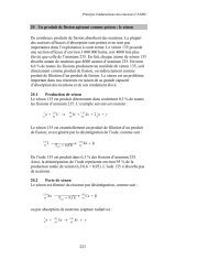
5. Validation of <strong>Codes</strong> <strong>and</strong> <strong>Methods</strong>The physics codes <strong>and</strong> methods are continuously being validated against measurements.Some measurements are per<strong>for</strong>med in the ZED-2 research reactor (zero-energyexperimental assembly) at the Chalk River Laboratories, while others are carried out inpower reactors during the commissioning phase or during operation. These measurementsinclude:a. Integral experiments in the ZED-2 reactor to obtain lattice material bucklings,reactivity coefficients, <strong>and</strong> reactivity worth of devices;b. Reactivity of individual <strong>and</strong> group of devices against moderator poison in powerreactors at cold conditions, at either fresh-fuel or equilibrium-fuelling irradiated-fuelconditions;c. Global flux distributions measured <strong>for</strong> various reactor configurations under either cold,zero-power or at-power conditions;d. Integral measurements of feedback reactivity due to changes in temperature <strong>and</strong>/orpower level; <strong>and</strong>e. Flux-transient measurements with in-core instrumentation following shutdownsystemactuation.Validation of all three levels of physics calculations has been extensively documented.The validation of the core-simulation results implicitly covers also the lattice-cell <strong>and</strong>supercell calculations, <strong>and</strong> involves the accuracy of the spatial flux distribution, which isone of the key end-products of the chain of calculations. Sample results of codevalidation against measurement data from the 1992 Point Lepreau restart commissioningphysics tests [12,13] are presented here <strong>for</strong> illustration.Table 1 shows the st<strong>and</strong>ard deviation of the differences between the measured <strong>and</strong>computed flux “response” to various perturbed-core configurations at the 102 vanadiumdetector locations. “Response” is defined as the ratio of flux at a given location in theperturbed core to the flux at the same location in the nominal-configuration core. Therelative accuracy of the various calculational methods is shown, including the results frompre-simulations per<strong>for</strong>med with assumed core conditions be<strong>for</strong>e the actual tests wereper<strong>for</strong>med.Figures 1a <strong>and</strong> 1b show comparisons of the flux response in horizontal <strong>and</strong> verticaldirections, respectively, <strong>for</strong> a perturbed-core configuration. The flux shape was highlydistorted <strong>by</strong> the 50%-insertion of two mechanical-control-absorber (MCA) rods <strong>and</strong> thewithdrawal of adjuster bank 1. The measurements, obtained using a travelling fluxdetector (TFD) scanning along selected detector assemblies locations, are compared withRFSP computed results using the uni<strong>for</strong>m-parameter diffusion method as well as the fluxmappingmethod.14
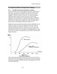
Figure 2 compares results of a *CERBERUS simulation of a reactor trip to the measuredresponse of shutdown-system in-core detectors. The reactor shutdown was initiated <strong>by</strong> amanual trip of shutdown system No. 1 (SDS1), <strong>and</strong> the power decreased to decay-powervalues in less than 2 s. The detector dynamic response <strong>and</strong> the electronic-circuitry signalprocessing were modelled. Note that the calculation results predict a power run-downrate slightly slower than the measured rate, which is on the conservative side from asafety-analysis perspective.The above sample validation results demonstrate the accuracy of the chain of codes insituations where the flux shape is highly distorted or the flux shape is rapidly changing.In summary, a high level of confidence in the physics codes <strong>and</strong> methods has beenculminated through continuous validation against actual operation data <strong>and</strong> operationexperience.6. References1. B. Rouben, “Description of the Lattice Code POWDERPUFS-V”, AECL Report,AECL-11357, 1995 October.2. J. Griffiths, “WIMS-AECL Users Manual”, AECL Report, RC-1176, COG-94-52,Rev. 3, 1998 March.3. J. R. Askew, F. J. Fayers <strong>and</strong> P. B. Kemshell, “A General Description of the LatticeCode WIMS”, Journal of the British Nuclear Society, 4 (4), 564, 1966.4. A. R. Dastur <strong>and</strong> D. B. Buss, “MULTICELL - A 3-D Program <strong>for</strong> the Simulation ofReactivity Devices in <strong>CANDU</strong>”, AECL Report, AECL-7544, 1983 February.5. B. J. Min <strong>and</strong> J. V. Donnelly, “WIMS-AECL/MULTICELL Calculations with SPH<strong>for</strong> Wolsong-1 Reactivity Devices”, Proceedings of the Korean Nuclear Society SpringMeeting, 1996 May.6. G. Marleau, A. Hébert <strong>and</strong> R. Roy, “A User’s Guide <strong>for</strong> DRAGON”, Report IGE-174, Rev. 1, Ecole Polytechnique de Montréal, 1996 March.7. B. Rouben, “Overview of Current RFSP-Code Capabilities <strong>for</strong> <strong>CANDU</strong> CoreAnalysis”, AECL Report, AECL-11407, 1996 January.8. S. Zhang <strong>and</strong> B. Rouben, “<strong>CANDU</strong> Fuel Management”, companion paper to presentpaper, CJNPE, 1999 May.9. B. Rouben <strong>and</strong> D. A. Jenkins, “A Review of the History-Based Methodology <strong>for</strong>Simulating <strong>CANDU</strong> <strong>Reactor</strong> Cores”, Proceedings of INC 93 International NuclearConference, Toronto, Ontario, Canada, 1993 October.10. K. O. Ott <strong>and</strong> D. A. Meneley, “Accuracy of the Quasistatic Treatment of Spatial<strong>Reactor</strong> Kinetics”, Nuclear Science <strong>and</strong> Engineering, 36, 402, 1969.11. H. C. Chow, B. Rouben, M. H. Younis, D. A. Jenkins, A. Baudouin <strong>and</strong> P.D.Thompson, “Simulation of <strong>Reactor</strong> Regulating System Action in RFSP”, Proceedingsof the 16 th Annual Conference, Canadian Nuclear Society, Saskatoon, Canada, 1995June.14
12. H. C. Chow <strong>and</strong> C. Newman, “1992 Point Lepreau Restart <strong>Physics</strong> Tests”,Proceedings of the 15 th Annual Conference of the Canadian Nuclear Society,Fredericton, N.B., Canada, 1994 June.13. D. A. Jenkins <strong>and</strong> E. G. Young, “Simulation of the 1992 SDS1 Trip Test at PointLepreau”, 1994 Nuclear Simulation Symposium, Pembroke, Ontario, Canada, 1994October.Table 1 Comparisons of Perturbation Response Measured <strong>by</strong> VanadiumDetectors <strong>and</strong> Computed <strong>by</strong> RFSPCalculationMethodPerturbed-core Configuration(St<strong>and</strong>ard Deviation of Difference at 102 Vanadium-Detector Locations)AverageSt<strong>and</strong>ardDeviationMCA Bank1 50%Inserted;AdjusterBank 1WithdrawnSORRod#1950%InsertedZone #2DrainedAdjusterRod #18WithdrawnAdjusterBank 1WithdrawnAdjusterBanks1-4Withdrawn*Diffusion(Pre-Simulation)Diffusion -Uni<strong>for</strong>mParameterDiffusion -History-Based5.8% 2.7% 2.1% 2.0% 2.2% 3.1% 3.0%1.2% 1.4% 2.8% 2.6% 2.5% 1.5% 2.0%1.2% 1.3% 1.6% 2.3% 2.5% 1.8% 1.8%**FluxMapping 0.6% 0.7% 0.3% 0.3% 0.3% 0.3% 0.4%* Pre-simulations were per<strong>for</strong>med be<strong>for</strong>e the actual tests, using assumed coreconditions <strong>and</strong> the uni<strong>for</strong>m-parameter method.** Flux-mapping calculations were done using the history-based diffusion-methodsolution as the fundamental mode.14
Figure 1a Flux Response ComparisonsRFSP vs. TFD Scan Along HFD #3(MCA Bank 1 Half-In / AA Bank 1 Out)Flux Response1.21.110.9TFD ScanDiffusion - Uni<strong>for</strong>mParameterMapping - History-BasedDiffusion Fundamental0.80.71 3 5 7 9 11 13 15 17 19Lattice ColumnFigure 1b Flux Response ComparisonsRFSP vs. TFD Scan Along VFD #16(MCA Bank 1 Half-In / AA Bank 1 Out)1.2Flux Response1.110.90.80.7TFD ScanDiffusion - Uni<strong>for</strong>mParameterMapping - History-BasedDifusion Fundamental0.60.5B C D E F G H J K L M N O P Q R S TLattice Row14
Figure 2 ROP Detector 4F Response in SDS1 Trip TestDetector Response10.90.80.70.60.50.40.30.20.100 0.2 0.4 0.6 0.8 1 1.2 1.4 1.6 1.8 2Time (s)RFSPSite Data14