Reactor Core Structure of Qinshan Phase III CANDU Nuclear Power ...
Reactor Core Structure of Qinshan Phase III CANDU Nuclear Power ...
Reactor Core Structure of Qinshan Phase III CANDU Nuclear Power ...

You also want an ePaper? Increase the reach of your titles
YUMPU automatically turns print PDFs into web optimized ePapers that Google loves.
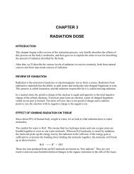
nuclear fission. Coolant flow through adjacent channels in the reactor is in opposite<br />
directions. During on-power refuelling, the fuelling machines first make a leak tight<br />
connection to both ends <strong>of</strong> a channel, then gains access by removing the closure plugs and<br />
shield plugs from both end fittings <strong>of</strong> the channel to be refuelled.<br />
The pressure tube and end<br />
fittings are manufactured to<br />
the requirements <strong>of</strong> the<br />
ASME Boiler and Pressure<br />
Vessel Code, Section <strong>III</strong>,<br />
“Rules for Construction <strong>of</strong><br />
<strong>Nuclear</strong> <strong>Power</strong> Plant<br />
Components”, Subsection<br />
NB, “Rules for Class 1<br />
Components” and form part<br />
<strong>of</strong> the primary heat<br />
transport system. The<br />
pressure tube has an inside<br />
diameter <strong>of</strong> about 104 mm, a<br />
wall thickness <strong>of</strong> about 4<br />
mm and a length <strong>of</strong> about 6.3<br />
m. The dissimilar metals <strong>of</strong><br />
the pressure tube and end fittings are joined by means <strong>of</strong> a high integrity, roll-expanded<br />
joint that has been qualified for in-reactor use by an extensive program.<br />
The Third <strong>Qinshan</strong> <strong>Nuclear</strong> <strong>Power</strong> Plant has a design life <strong>of</strong> 40 years at an average<br />
capacity <strong>of</strong> 85%. This is readily achieved, in part, because the design <strong>of</strong> the fuel channel<br />
permits their replacement. The pressure tubes have a design life <strong>of</strong> 25 years at an average<br />
capacity factor <strong>of</strong> 85%.<br />
Reactivity Control Units<br />
General<br />
The reactivity control units form the in-core sensing and actuating portions <strong>of</strong> the reactor<br />
regulating system and the two reactor shutdown systems, shutdown system 1 and<br />
shutdown system 2. Since they are physically parts <strong>of</strong> the reactor assembly, they share<br />
many common bases for their mechanical design. The following sections describe these<br />
common aspects <strong>of</strong> the reactivity control units.<br />
All reactivity control units perform one <strong>of</strong> three functions for their respective system(s):