Acoustics Bulletin Jul-Aug 2011 - Institute of Acoustics
Acoustics Bulletin Jul-Aug 2011 - Institute of Acoustics
Acoustics Bulletin Jul-Aug 2011 - Institute of Acoustics

Create successful ePaper yourself
Turn your PDF publications into a flip-book with our unique Google optimized e-Paper software.
TECHNICAL<br />
CONTRIBUTIONS<br />
Simulation and application <strong>of</strong> beam-shaped… - continued from page 29<br />
subwo<strong>of</strong>er is strongly affected by the radiation impedance (the acoustic<br />
load) and the cabinet diffraction. Both the acoustic load and the<br />
diffraction are defined by the size and shape <strong>of</strong> the array and the<br />
position <strong>of</strong> the loudspeaker in the array.<br />
In practice, subwo<strong>of</strong>er arrays are <strong>of</strong>ten stacked on the floor or stage.<br />
Assuming the ground plane is acoustically hard and large compared to<br />
the acoustic wavelength, it can be modelled as a infinite baffle. At first<br />
sight it might be expected that the radiation pattern <strong>of</strong> the individual<br />
array elements does not change, and that the effect <strong>of</strong> the ground plane<br />
can be simply modelled by adding a mirror-image <strong>of</strong> the source.<br />
However, owing to the contact interface between the array and the<br />
ground plane, the sound diffraction around the array is affected too,<br />
because the 'path' under the array is now blocked.<br />
From the above it is evident that the directional response <strong>of</strong> a<br />
subwo<strong>of</strong>er is not only affected by the array geometry, but also by the<br />
radiation condition (full-space or half-space). So, in order to model<br />
accurately and optimise a (differential) subwo<strong>of</strong>er array, the actual<br />
acoustic boundary conditions (ABC) should be taken into account.<br />
Anechoic measurement <strong>of</strong> the radiation characteristics <strong>of</strong> a subwo<strong>of</strong>er<br />
under realistic radiation conditions is practically impossible because <strong>of</strong><br />
the large array dimensions and unlimited number <strong>of</strong> variations in array<br />
set-up. Therefore, a computationally efficient, hybrid PSM-BEM<br />
approach was developed. The principles behind the PSM-BEM approach<br />
are reviewed below.<br />
The PSM-BEM model<br />
Using the acoustic Boundary Element Method[4] (BEM) it is possible<br />
to model diffraction and coupling effects for low and low/mid<br />
frequencies accurately. The BEM is based on the Helmholtz integral<br />
equation (HIE). On the basis <strong>of</strong> the discrete distribution <strong>of</strong> the normal<br />
component <strong>of</strong> the particle velocity at the boundaries <strong>of</strong> a radiating<br />
object, the sound radiation can be calculated in all directions outside<br />
the object. Unfortunately, direct implementation <strong>of</strong> the BEM into the<br />
DDA modelling s<strong>of</strong>tware would lead to dramatically increased<br />
computation times.<br />
The idea behind the PSM-BEM approach is the following. Exactly as in<br />
the PSM, the array is modelled as a set <strong>of</strong> directional point sources. In<br />
contrast to the PSM, the spectral and directional behaviour <strong>of</strong> each<br />
point source is no longer given by the measured free field response <strong>of</strong><br />
the loudspeaker, but is replaced by BEM-calculated directivity data <strong>of</strong><br />
the loudspeaker facing the actual acoustic boundary conditions. A<br />
prerequisite is that the volume velocity <strong>of</strong> a moving loudspeaker cone<br />
is unaffected by the acoustic load. As the particle velocity right in front<br />
<strong>of</strong> the cone and the ports is almost completely dictated by the driver,<br />
this is a valid assumption.<br />
In order to model ground-stacked arrays, the half-space formulation <strong>of</strong><br />
the HIE is implemented in the propriety BEM algorithms. The<br />
PSM-BEM model now handles flown subwo<strong>of</strong>er arrays, radiating into<br />
full-space, as well as ground-stacked arrays, which are facing half-space<br />
radiation conditions.<br />
Calculation <strong>of</strong> directivity data<br />
Procedure<br />
Using the BEM, a library with far field radiation data <strong>of</strong> each AXYS<br />
subwo<strong>of</strong>er model has been pre-calculated for the most common<br />
acoustic boundary conditions. Each ABC is defined by three<br />
parameters: the number <strong>of</strong> cabinets in the array, the position <strong>of</strong> the<br />
active subwo<strong>of</strong>er in the array and the radiation condition (either fullspace<br />
or half-space). The BEM calculation procedure followed is<br />
explained below.<br />
a<br />
b<br />
c<br />
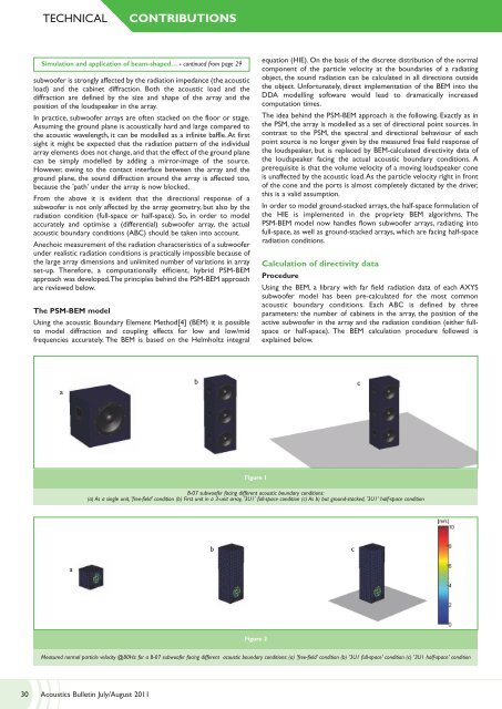
Figure 1<br />
B-07 subwo<strong>of</strong>er facing different acoustic boundary conditions:<br />
(a) As a single unit, 'free-field' condition (b) First unit in a 3-unit array, '3U1' full-space condition (c) As b) but ground-stacked, '3U1' half-space condition<br />
b<br />
c<br />
a<br />
Figure 2<br />
Measured normal particle velocity @80Hz for a B-07 subwo<strong>of</strong>er facing different acoustic boundary conditions: (a) 'free-field' condition (b) '3U1 full-space' condition (c) '3U1 half-space' condition<br />
30 <strong>Acoustics</strong> <strong>Bulletin</strong> <strong>Jul</strong>y/<strong>Aug</strong>ust <strong>2011</strong>