Acoustics Bulletin Jul-Aug 2011 - Institute of Acoustics
Acoustics Bulletin Jul-Aug 2011 - Institute of Acoustics
Acoustics Bulletin Jul-Aug 2011 - Institute of Acoustics

You also want an ePaper? Increase the reach of your titles
YUMPU automatically turns print PDFs into web optimized ePapers that Google loves.
TECHNICAL<br />
CONTRIBUTIONS<br />
Figure 7<br />
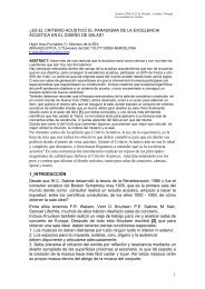
Figure 8<br />
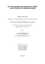
Photograph <strong>of</strong> a sample <strong>of</strong> defective ceramic, showing ‘pinholes’.<br />
A TV demonstration <strong>of</strong> sound absorption… - continued from page 37<br />
mechanism for sound absorption). This effect would be detected by the<br />
microphone/hydrophone, and then explained to the audience to link the<br />
space shuttle to the submarine in a way which makes the underlying<br />
physics clear. The apparatus is shown under construction on location in<br />
Figure 4.<br />
Details on how the apparatus is constructed, and the signals designed,<br />
can be found in reference [1]. Practical details range from the mundane<br />
to the subtle. For example, the air-filled tube needed to be sealed at the<br />
base (Figure 4(b)), and fitted with an exhaust pipe to allow displaced<br />
clean air to vent from the base <strong>of</strong> the pipe, so allowing the fog to fall to<br />
the base <strong>of</strong> the pipe and completely fill it. At the other extreme, the<br />
choice <strong>of</strong> signal had to be selected such that it would be audible to the<br />
audience when no bubbles or fog were added, but be dramatically<br />
attenuated when fog and bubbles were added. This proved challenging,<br />
since there was not great flexibility in the bubble and droplet<br />
populations that could be generated with the simple apparatus to hand.<br />
A relatively high frequency audio signal was required, which was<br />
sufficiently characteristic for the audience to latch onto it above the<br />
background noise. An upwards linear chirp sweep from 10 kHz to 20<br />
kHz was chosen since it was sufficiently high to produce attenuation<br />
that could be heard by the listeners, but not so high as to be difficult for<br />
a wide age range <strong>of</strong> listeners to hear. The chirp is repeated every second<br />
to facilitate the audience in hearing the changes due to addition <strong>of</strong><br />
bubbles/droplets. Rather than try to enable the audience/viewer to hear<br />
the sound emitted directly by each tube, it was most convenient to let<br />
them listen to the output <strong>of</strong> the microphone/hydrophone (which for<br />
the TV show was fed directly to the sound channel, but for live<br />
audiences can be transmitted by loudspeaker or, if feedback is a<br />
problem, by headphones).<br />
Having found a signal which can be heard by the audience in fog-free and<br />
bubble-free conditions but which is dramatically attenuated by the fogs<br />
we could easily make (Figure 4(c)), the objective was to ensure that we<br />
could make a bubble population which would also dramatically<br />
attenuate the signal. This bubble population would need to one that<br />
could easily be injected into the water pipe using a standard portable<br />
compressor and hypodermic needle. The difficulty here was that this<br />
required bubbles which are smaller than those produced by simple<br />
injection[1]. Simply reducing the bore <strong>of</strong> the hypodermic needle does<br />
not produce smaller bubbles: although a small bubble might initially be<br />
released from the needle, it does not rise sufficiently rapidly under<br />
buoyancy to prevent it coalescing with the next bubble that is growing<br />
at the needle tip (Figure 5). The result is that the only bubble that can<br />
rise away from the needle swiftly enough to avoid any more coalescence<br />
is one that has already grown large through such coalescence. The<br />
solution was to place the vibrator from a mobile phone on the needle<br />
outside the pipe at such a position as to produce maximum<br />
displacement at the needle tip. This removed the successor bubble<br />
growing at the tip away from the location <strong>of</strong> the newly released bubble,<br />
and enabled sufficiently small bubbles to be generated (for details, see<br />
the reference list[1,9] and the video at the associated web page).<br />
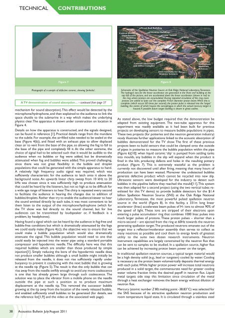
Schematic <strong>of</strong> the Spallation Neutron Source at Oak Ridge National Laboratory, Tennessee.<br />
The hydrogen ions for the linear accelerator are generated in the ‘front end’ building at the<br />
top left <strong>of</strong> the picture, and are accelerated down the linear accelerator (shown in red) to<br />
the ring, where protons are accumulated. During repeated circulation <strong>of</strong> the ring, more<br />
protons are added to ‘pain out’ the complete 9-inch diameter proton beam. When this is<br />
complete (which occurs 60 times per second), the proton pulse is released into the ‘target’<br />
building, the centre <strong>of</strong> which houses the sarcophagus in which the actual mercury target is<br />
housed. A possible future target building is shown in ghost outline.<br />
As stated above, the low budget required that the demonstration be<br />
adapted from existing equipment. The two-tube apparatus for this<br />
experiment was readily available as it had been built for previous<br />
projects on developing sensors to measure bubble populations in pipes.<br />
These two projects (for potteries and the neutron generation industry)<br />
nicely illustrate further applications linked to the acoustic absorption <strong>of</strong><br />
bubbles demonstrated for the TV show. The first <strong>of</strong> these previous<br />
projects been to build sensors that could be clamped onto the outside<br />
<strong>of</strong> pipes in potteries to measure the bubble population within the pipe<br />
(Figure 6)[10]: when liquid ceramic ‘slip’ is pumped from settling tanks<br />
into moulds, any bubbles in the slip will expand when the product is<br />
fired in the kiln, producing defects and holes in the resulting pottery<br />
product (Figure 7). This is extremely wasteful as the problem is<br />
currently not discovered until after firing, meaning that many hours <strong>of</strong><br />
production can have been wasted. Moreover the undetected bubbles<br />
generate defective product which cannot be recycled into new slip.<br />
Ultrasonic sensors were developed for the industry to detect such<br />
bubbles in the pipeline before they reached the mould[11]. This system<br />
was then adapted for a second project (using the two vertical tubes reenlisted<br />
for this TV demo) to provide bubble detectors for the $1.4<br />
billion Spallation Neutron Source (SNS) at the Oak Ridge National<br />
Laboratory, Tennessee, the most powerful pulsed spallation neutron<br />
source in the world (Figure 8). In this facility, a 331m long linear<br />
accelerator (linac) accelerates beam pulses <strong>of</strong> H- ions to almost 90% <strong>of</strong><br />
the speed <strong>of</strong> light. These ions are stripped <strong>of</strong> their electrons upon<br />
entering a pulse accumulator ring that combines 1000 linac pulses into<br />
much larger pulses <strong>of</strong> protons. These proton pulses – shorter than a<br />
micro-second – are ejected from the ring at 60Hz towards the neutron<br />
generating spallation target. The produced neutrons emanate out <strong>of</strong> the<br />
target into a reflector/moderator assembly than serves to collect as<br />
many neutrons as possible and cool them to energy levels <strong>of</strong> greatest<br />
utility to the suite two dozen research instruments. Neutron<br />
instrument capabilities are largely constrained by the neutron flux that<br />
can be sent to samples to be studied. In a spallation source, higher flux<br />
can be achieved by increasing proton beam power on the target.<br />
In traditional spallation neutron sources, a typical target material would<br />
be a high density solid (e.g., lead or tungsten) cooled by water. Cooling<br />
is necessary as the proton beam volumetrically deposits thermal energy<br />
with each pulse. While higher proton power will increase total neutrons<br />
produced in a solid target, the commensurate need for greater cooling<br />
water volume fraction limits the desired pay<strong>of</strong>f in neutron flux. Liquid<br />
metal targets side step this limitation since circulation <strong>of</strong> the metal<br />
through a heat exchanger removes the beam energy without dilution <strong>of</strong><br />
neutron flux.<br />
Mercury (atomic number Z 80; melting point -38.83°C) was selected for<br />
the SNS because <strong>of</strong> its attractive spallation neutron production and<br />
room temperature liquid state. It is circulated through a stainless steel<br />
38 <strong>Acoustics</strong> <strong>Bulletin</strong> <strong>Jul</strong>y/<strong>Aug</strong>ust <strong>2011</strong>