Create successful ePaper yourself
Turn your PDF publications into a flip-book with our unique Google optimized e-Paper software.
e-mail: info@direktronik.se<br />
tel: 08-52 400 700 fax: 08-520 18121<br />
<strong>DS202</strong> <strong>Serial</strong> <strong>Device</strong> <strong>Server</strong><br />
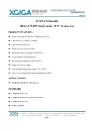
The <strong>DS202</strong> is a <strong>Serial</strong> <strong>Device</strong> <strong>Server</strong> for external use. <strong>Device</strong> hardware includes one<br />
10/100BaseT Ethernet port, one RS232 serial port and an internal processor that<br />
"glues" network and serial sides together. Internally, the <strong>DS202</strong> is based on the<br />
EM202 Ethernet Module.<br />
From the hardware standpoint, the <strong>DS202</strong> can be viewed as a universal platform<br />
suitable for running a variety of network and serial communications-related<br />
applications. It is the application firmware, not the hardware that gives the <strong>DS202</strong><br />
most of its functionality. The firmware is currently in its 3rd generation ("Release3").<br />
©2000-2004 Tibbo Technology Inc.
The application firmware of the <strong>DS202</strong> can be upgraded through the device's serial<br />
port or Ethernet port. <strong>Serial</strong> upgrades are facilitated by a so-called Monitor- a fixed<br />
"service" firmware inside the <strong>DS202</strong>. Network upgrades rely on the application<br />
firmware itself- there is a self upgrade algorithm that will be detailed later. The<br />
<strong>DS202</strong> is supplied with the application firmware already pre-loaded.<br />
Since most of the <strong>DS202</strong>'s operation is defined by its firmware the major part of the<br />
functional description can be found in the<br />
<strong>Device</strong> <strong>Server</strong> Application Firmware Manual. This <strong>DS202</strong> <strong>Serial</strong> <strong>Device</strong> <strong>Server</strong> Manual<br />
focuses on the hardware portion of the <strong>DS202</strong>.<br />
<strong>DS202</strong> 2.3.3.1 connectors and controls<br />
Click on one of the links provided below to learn more about the <strong>DS202</strong>:<br />
· Power Jack (input power is 10-25VDC, adaptor current rating must be no less<br />
than 500mA)<br />
· Ethernet port pin assignment<br />
· RS232 port pin assignment<br />
· Status LEDs<br />
· Setup button<br />
Power Jack<br />
Power Jack of the <strong>DS202</strong> accepts "small" power connectors with 3.5mm diameter.<br />
Use ARP-P0006, ARP-P0007, or ARP-P0008 power adaptor supplied by Tibbo or<br />
similar adaptor. Acceptable power supply voltage range is 10-25VDC. Adaptor<br />
current rating should be at least 500mA. On the power jack, the ground is "on the<br />
outside", as shown on the figure below.<br />
©2000-2004 Tibbo Technology Inc.
Ethernet port pin assignment<br />
Ethernet port of the <strong>DS202</strong> is of 10/100BaseT type.<br />
Connector is of RJ45 type, pin assignment is as follows:<br />
#1 TX+<br />
#2 TX-<br />
#3 RX+<br />
#4 <br />
#5 <br />
#6 RX-<br />
#7 <br />
#8 <br />
RS232 port pin assignment<br />
DB9M RS232 connector has the following pin assignment:<br />
©2000-2004 Tibbo Technology Inc.
#1 <br />
#2 RX (input)<br />
#3 TX (output)<br />
#4 <br />
#5 Ground<br />
#6 <br />
#7 RTS (output)<br />
#8 CTS (input)<br />
#9 <br />
Status LEDs<br />
The <strong>DS202</strong> has two pairs of status LEDs: one on the Ethernet connector itself (left<br />
side), and one on top of the <strong>Device</strong>. Both pairs are controlled by the same internal<br />
circuitry and exhibit exactly the same behavior.<br />
Status LEDs display various status information depending on what firmware is<br />
running at the moment. Follow the links below to learn more about the behaviour of<br />
these LEDs under different conditions:<br />
· Status LED behavior in the monitor firmware<br />
· Status LED behavior in the application firmware<br />
There are also two Ethernet Status LEDs- Green and Yellow- located on the<br />
Ethernet connector (right side):<br />
· Link/Data LED (green) is turned on when "live" Ethernet cable is plugged into the<br />
Module. The LED is temporarily switched off whenever an Ethernet packet is<br />
received.<br />
· 100BaseT LED (yellow) is turned on when the EM202 links with the hub at<br />
100Mb. The LED is off when the link is established at 10Mb.<br />
Setup button<br />
The setup button is located next to the Ethernet port of the <strong>DS202</strong>.<br />
The Button is used to select an operating mode of the <strong>DS202</strong>:<br />
· When the <strong>DS202</strong> is powered up with the button pressed it enters a serial upgrade<br />
mode in which new application firmware file can be uploaded into the <strong>DS202</strong><br />
through its serial port. If the <strong>DS202</strong> is powered up with the setup button not<br />
pressed the <strong>Device</strong> proceeds to running its current application firmware. This<br />
functionality is delivered by the Monitor firmware component of the <strong>DS202</strong>.<br />
· When the application firmware is already running the setup button is used to make<br />
the <strong>DS202</strong> enter the serial programming mode (hence, the name of a button)*.<br />
* Strictly speaking, this is a functionality that is defined by the application<br />
firmware, not the <strong>DS202</strong> hardware.<br />
©2000-2004 Tibbo Technology Inc.
Specifications 2.3.3.2 and <strong>DS202</strong> modifications<br />
The <strong>DS202</strong> has one submodel in circulation- <strong>DS202</strong>R-00.<br />
<strong>Device</strong> specifications are presented in the table below.<br />
Parameter<br />
Ethernet interface<br />
<strong>Serial</strong> interface and I/O lines<br />
<strong>DS202</strong>R-00<br />
10/100BaseT Ethernet<br />
Routing buffers size 12Kbytes x 2*<br />
Power requirements<br />
Operating temperature<br />
Operating relative humidity 10-90%<br />
Mechanical dimensions<br />
Carton dimensions ("bare" <strong>DS202</strong>)<br />
Gross weight ("bare" <strong>DS202</strong>) 110g.<br />
Carton dimensions (<strong>DS202</strong>-KIT)<br />
Gross weight (<strong>DS202</strong>-KIT) 950g.<br />
RS232 (TX,RX,RTS,CTS,DTR,DSR)<br />
DC 10-25V, use adaptor with current rating of<br />
at least 500mA<br />
-5 to +70 degrees C<br />
60x47x30mm<br />
125x95x52mm<br />
325x45x90mm<br />
* Maximum possible buffer size. Actual size may be smaller depending on how<br />
much RAM is "consumed" by the firmware<br />
Kits and Accessories<br />
Tibbo supplies the following Accessories:<br />
· WAS-P0004(B) DS-to-device serial cable (replaces now obsolete WAS-1404)<br />
· WAS-P0005(B) DS-to-PC serial cable (replaces now obsolete WAS-1455)<br />
· WAS-1499 "straight" Ethernet cable (DS-to-hub cable)<br />
· WAS-1498 "crossover" Ethernet cable (DS-to-device cable)<br />
· TB100 Terminal Block Adaptor<br />
· 12VDC/500mA Power Adaptors<br />
· DMK100 DIN Rail/Wall Mounting Kit<br />
The following Starter Kits are available:<br />
· DS100R-SK Starter Kit. The Kit includes all necessary parts for evaluation of the<br />
DS100R <strong>Serial</strong> <strong>Device</strong> <strong>Server</strong>:<br />
· DS100R <strong>Serial</strong> <strong>Device</strong> <strong>Server</strong>;<br />
· WAS-P0004(B) DS-to-device serial cable;<br />
· WAS-P0005(B) DS-to-PC serial cable;<br />
· WAS-1499 "straight" Ethernet cable;<br />
· WAS-1498 "crossover" Ethernet cable;<br />
· 12VDC/500mA Power Adaptor.<br />
©2000-2004 Tibbo Technology Inc.<br />
e-mail: info@direktronik.se<br />
tel: 08-52 400 700 fax: 08-520 18121