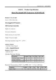
GLC-TG Small Form-Factor Pluggable (SFP)
GLC-TG Small Form-Factor Pluggable (SFP)
GLC-TG Small Form-Factor Pluggable (SFP)

You also want an ePaper? Increase the reach of your titles
YUMPU automatically turns print PDFs into web optimized ePapers that Google loves.
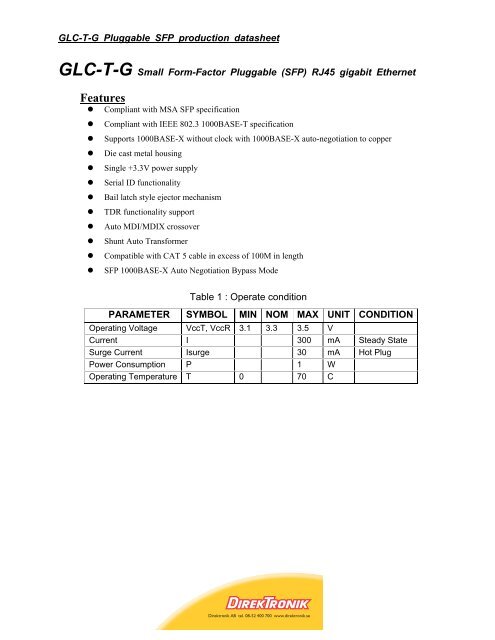
<strong>GLC</strong>-T-G <strong>Pluggable</strong> <strong>SFP</strong> production datasheet<strong>GLC</strong>-T-G <strong>Small</strong> <strong>Form</strong>-<strong>Factor</strong> <strong>Pluggable</strong> (<strong>SFP</strong>) RJ45 gigabit EthernetFeatures• Compliant with MSA <strong>SFP</strong> specification• Compliant with IEEE 802.3 1000BASE-T specification• Supports 1000BASE-X without clock with 1000BASE-X auto-negotiation to copper• Die cast metal housing• Single +3.3V power supply• Serial ID functionality• Bail latch style ejector mechanism• TDR functionality support• Auto MDI/MDIX crossover• Shunt Auto Transformer• Compatible with CAT 5 cable in excess of 100M in length• <strong>SFP</strong> 1000BASE-X Auto Negotiation Bypass ModeTable 1 : Operate conditionPARAMETER SYMBOL MIN NOM MAX UNIT CONDITIONOperating Voltage VccT, VccR 3.1 3.3 3.5 VCurrent I 300 mA Steady StateSurge Current Isurge 30 mA Hot PlugPower Consumption P 1 WOperating Temperature T 0 70 C
<strong>GLC</strong>-T-G <strong>Pluggable</strong> <strong>SFP</strong> production datasheetBLOCK DIAGRAMThe RJ45 Gigabit Ethernet pluggable transceiver module is a high performance integrated duplex datalink for bi-directional communication over CAT 5 unshielded twisted pair copper cable. It is compliantwith the MSA <strong>Small</strong> <strong>Form</strong> <strong>Factor</strong> <strong>Pluggable</strong> (<strong>SFP</strong>) specification. The RJ45 transceiver is specificallydesigned for high speed Gigabit Ethernet data links at 1.25 Gbaud. The transceiver is hot pluggableand operates at +3.3V.
<strong>Small</strong> <strong>Form</strong>-<strong>Factor</strong> <strong>Pluggable</strong> (<strong>SFP</strong>) J45 gigabit EthernetHost Board InterfaceThe table below shows the host interface signals and their functions.Table 2: Pin Function Definitions.PIN NO. NAME FUNCTION SEQ. NOTESPIN 1 VeeT Transmitter Ground 1PIN 2 TX_FAULT Transmitter Fault Indication 3VeeT and VeeR areconnected in <strong>SFP</strong>.Not Implemented. Tied toVeeT in <strong>SFP</strong>.PIN 3 TX_DISABLE Transmitter Disable 3 See TX Disable.PIN 4 MOD DEF (2) Module Definition 2 3PIN 5 MOD DEF (1) Module Definition 1 3Data Line for Serial ID andBidirectional Data Transferbus.Clock Line for Serial ID andBidirectional Data Transferbus.PIN 6 MOD DEF (0) Module Definition 0 3 Tied to Vee in <strong>SFP</strong>.PIN 7 RATE SELECT Not Implemented 3Not implemented. 33Kpulldown to Vee in <strong>SFP</strong>.PIN 8 LOS Loss of Signal 3 See LOS option.PIN 9 VeeR Receiver Ground 1VeeT and VeeR areconnected in <strong>SFP</strong>.PIN 10 VeeR Receiver Ground 1VeeT and VeeR areconnected in <strong>SFP</strong>.PIN 11 VeeR Receiver Ground 1VeeT and VeeR areconnected in <strong>SFP</strong>.PIN 12 RD- Inverted Received Data out 3AC coupled 100 ohmdifferential high speed dataPIN 13RD+Non-Inverted Received DataoutPIN 14 VeeR Receiver Ground 1PIN 15 VccR Receiver Power 2PIN 16 VccT Transmitter Power 2PIN 17 VeeT Transmitter Ground 13lines.AC coupled 100 ohmdifferential high speed datalines.VeeT and VeeR areconnected in <strong>SFP</strong>.VccR and VccT areconnected in <strong>SFP</strong>.VccR and VccT areconnected in <strong>SFP</strong>.VeeT and VeeR areconnected in <strong>SFP</strong>.PIN 18 TD+ Non-inverted Data In 3AC coupled 100 ohmdifferential high speed datalines.
<strong>Small</strong> <strong>Form</strong>-<strong>Factor</strong> <strong>Pluggable</strong> (<strong>SFP</strong>) J45 gigabit EthernetPIN 19 TD- Inverted Data In 3PIN 20 VeeT Transmitter Ground 1AC coupled 100 ohmdifferential high speed datalines.VeeT and VeeR areconnected in <strong>SFP</strong>.TX DisablePulled up to Vcc with 10K ohm resistor in <strong>SFP</strong>. For normal operation the Host must hold the TXDisable input low. An open or high input to the <strong>SFP</strong> holds the PHY in reset. The reset condition isremoved 175ms after TX Disable goes low.LOS OptionThe <strong>SFP</strong> MSA specification defines a pin called LOS to indicate loss of signal to the motherboard.This is an output of the <strong>SFP</strong> module and an input to the motherboard. Eflow’s 1000Base-T copper<strong>SFP</strong> Transceiver normally comes with the LOS signal connected to ground. The transceiver canbe ordered with this signal connected to the LED_Link1000 output of the PHY to indicate a goodlinkBi-directional Data Transfer BusThe Eflow 1000 Base-T Copper <strong>SFP</strong> Transceiver supports a bi-directional data transfer bus (BDT)to communicate with the PHY. The BDT operates with the same serial data line (SDA-MOD_DEF[2]) and serial clock line (SCL MOD_DEF[1]) that are used for serial identification. Thedevice address for the PHY is 1010110X binary. The SDA is a bi-directional line while the SCLline is not. Both of the bus interface lines are high when the bus is inactive. The PHY operatesas the Slave port of the bus interface and all references to Slave refer to the PHY.The PHY BDT features are7 bit device addresses / 8 bit data transfers100 Kbps mode400 Kbps modeTermination CircuitsInputs to the transceiver are AC coupled and internally terminated through 50 ohms. Thesemodules can operate with PECL or ECL logic levels. The input signal must have at least a 325mVpeak-to-peak (single ended) signal swing. Output from the receiver section of the module is alsoAC coupled and is expected to drive a 50 ohm load. Different termination strategies may berequired depending on the particular Serializer/Deserializer chip set used. The transceiver isdesigned with AC coupled data inputs and outputs to provide the following advantages:Close positioning of SERDES with respect to transceiver; allows for shorter line lengths and atGigabit speeds reduces EMI.
<strong>Small</strong> <strong>Form</strong>-<strong>Factor</strong> <strong>Pluggable</strong> (<strong>SFP</strong>) J45 gigabit EthernetMinimum number of external components. Internal termination reduces the potential forunterminated stubs which would otherwise increase jitter andreduce transmission margin.Subsequently, this affords the customer the ability to optimally locate the SERDES as close to thetransceiver as possible and save valuable real estate. At Gigabit rates this can provide asignificant advantage resulting in better transmission performance and accordingly better signalintegrity.Power CouplingA suggested layout for power and ground connections is given in Figure 1 below. Connections aremade via separate voltage and ground planes. The mounting posts are at case ground andshould not be connected to circuit ground. The ferrite bead should provide a real impedance of 50to 100 ohms at 100 to 1000 MHz. Bypass capacitors should be placed as close to the 20 pinconnector as possible.Figure 1: Suggested Power CouplingMechanical DescriptionThe transceiver shall be compliant with common <strong>SFP</strong> mechanical outline1000Base-T <strong>SFP</strong> Transceiver DimensionsFigure 2 Illustrates the Mechanical Dimensions of the Transceiver
<strong>Small</strong> <strong>Form</strong>-<strong>Factor</strong> <strong>Pluggable</strong> (<strong>SFP</strong>) J45 gigabit EthernetFigure 2 Mechanical Dimensions of TransceiverMating of <strong>SFP</strong> Transceiver to <strong>SFP</strong> Host Board ConnectorThe pads on the PCB of the <strong>SFP</strong> transceiver shall be designed for a sequenced mating asfollows:First mate: Ground contactsSecond mate: Power contactsThird mate: Signal contactsThe <strong>SFP</strong> MSA specification for a typical contact pad plating for the PCB is 0.38 micrometersminimum hard gold over 1.27 micrometers minimum thick nickel. To ensure the long termreliability performance after a minimum of 50 insertion removal cycles, the contact plating of thetransceiver is 0.762 micron (30 microinches) over 3.81 micron (150 microinches) of Ni on Cucontact pads.RJ45 ConnectorRJ45 connector shall support shielded and unshielded cables. Also, the connector ismechanically robust enough and designed to prevent loss of link, when the cable is positioned ormoves in different angles. The connector shall pass the “wiggle” RJ45 connector operationalstress test. During the test, after the cable is plugged in, the cable is moved in circle to cover all360 deg in the vertical plane, while the data traffic is on. There shall be no link or data loss.