Installation Wiring Diagram
Installation Wiring Diagram
Installation Wiring Diagram

You also want an ePaper? Increase the reach of your titles
YUMPU automatically turns print PDFs into web optimized ePapers that Google loves.
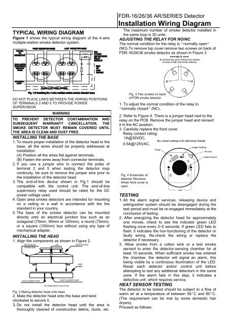
TYPICAL WIRING DIAGRAM<br />
Figure 1 shows the typical wiring diagram of the 4-wire<br />
multiple-station smoke detector system.<br />
FDR-16/26/36 AR/SERIES Detector<br />
<strong>Installation</strong> <strong>Wiring</strong> <strong>Diagram</strong><br />
The maximum number of smoke detector installed in<br />
the same loop is 30 units.<br />
ADJUSTING THE RELAY FOR NO/NC<br />
The normal condition for the relay is “normally open”<br />
(NO).To remove top cover remove two screws on back of<br />
FDR-16/26/36 smoke detector as shown in Figure 3<br />
DO NOT PLACE LINKS BETWEEN THE WIRING POSITIONS<br />
OF TERMINALS 2 AND 5 TO PROVIDE POWER<br />
SUPERVISION<br />
WARNING<br />
TO PREVENT DETECTOR CONTAMINATION AND<br />
SUBSEQUENT WARRANTY CANCELLATION, THE<br />
SMOKE DETECTOR MUST REMAIN COVERED UNTIL<br />
THE AREA IS CLEAN AND DUST FREE.<br />
INSTALLING THE BASE<br />
1. To insure proper installation of the detector head to the<br />
base, all the wires should be properly addressed at<br />
installation:<br />
(A) Position all the wires flat against terminals.<br />
(B) Fasten the wires away from connector terminals.<br />
2. If you use a jumper wire to connect the poles of<br />
terminal 2 and 5 when testing the detector loop<br />
continuity, be sure to remove the jumper wire prior to<br />
the installation of the detector head.<br />
3. The end-of-line device shown in Fig.1 should be<br />
compatible with the control unit. The end-of-line<br />
supervisory relay used should be rated for the DC<br />
power voltage used.<br />
4. Open area smoke detectors are intended for mounting<br />
on a ceiling or a wall in accordance with the fire<br />
standard in your country.<br />
5. The base of the smoke detector can be mounted<br />
directly onto an electrical junction box such as an<br />
octagonal (75mm, 90mm or 100mm), a round (75mm),<br />
or a square (100mm) box without using any type of<br />
mechanical adapter.<br />
INSTALLING THE HEAD<br />
1. Align the components as shown in Figure 2.<br />
Fig. 2 Mating detector head onto base<br />
2. Mate the detector head onto the base and twist<br />
clockwise to secure it.<br />
3. Do not install the detector head until the area is<br />
thoroughly cleaned of construction debris, dusts, etc.<br />
Fig. 3 Two screws on back<br />
of FDR smoke detector<br />
1. To adjust the normal condition of the relay to<br />
“normally closed” (NC),<br />
2. Refer to Figure 4. There is a jumper head next to the<br />
relay on the PCB. Remove the jumper head and reinsert<br />
it in the NC position.<br />
3. Carefully replace the front cover.<br />
Relay contact rating:<br />
1A@30VDC,<br />
0.5A@125VAC.<br />
Fig. 4 Schematic of<br />
detector Structure<br />
When front cover is<br />
open.<br />
TESTING<br />
1. All the alarm signal services, releasing device and<br />
extinguisher system should be disengaged during the<br />
test period and must be re-engaged immediately at the<br />
conclusion of testing.<br />
2. After energizing the detector head for approximately<br />
one minute, check to see the indicator green LED<br />
flashing once every 3~5 seconds. If green LED fails to<br />
flash, it indicates the non-functioning of the detector or<br />
faulty wiring. Re-check the wiring or replace the<br />
detector if necessary.<br />
3. Allow smoke from a cotton wick or a test smoke<br />
aerosol to enter the detector-sensing chamber for at<br />
least 10 seconds. When sufficient smoke has entered<br />
the chamber, the detector will signal an alarm, this<br />
being visible by a continuous illumination of the LED.<br />
Reset each detector and/or control unit before<br />
attempting to test any additional detectors in the same<br />
zone. If the alarm fails in this step, it indicates a<br />
defective unit, which requires service.<br />
HEAT SENSOR TESTING<br />
The detector to be tested should be subject to a flow of<br />
warm air at a temperature of between 56°C and 80°C.<br />
(The requirement can be met by some domestic hair<br />
dryers).<br />
Proceed as follows:
1. Switch on the warm airflow and check that temperature<br />
is correct and stable.<br />
2. From a distance of several inches, direct the airflow at<br />
the guard protecting the thermistor. The detector<br />
should alarm within 30 seconds.<br />
3. Upon alarm immediately remove the heat source and<br />
check that the red LED of the detector is illuminated.<br />
Reset the detector from the control panel.<br />
4.If detector fails to go into alarm mode within 30<br />
seconds it is too insensitive and needs to be returned<br />
to the distributor for servicing.<br />
5. After testing, check that the system is set for normal<br />
operation and notify the appropriate authorities that the<br />
testing operation is complete and the system is active<br />
again.<br />
NOT SUITABLE FOR INSTALLATION IN AREAS<br />
WHERE AIR VELOCITIES EXCEED 300 ft/min<br />
SPECIFICATION<br />
Model 2/4<br />
wire<br />
Ther<br />
mal<br />
Voltage<br />
DC<br />
Standby<br />
Current<br />
(Max.)<br />
Alarm<br />
Current<br />
(Max.)<br />
Surge<br />
Current<br />
(Max.)<br />
Star-Up<br />
Time<br />
(Max.)<br />
MAINTENANCE<br />
The recommended minimum requirement for detector<br />
maintenance consists of an annual cleaning of dust from<br />
the detector head by using a vacuum cleaner cleaning<br />
program should be agreed to the individual environment<br />
in conformance with NFPA-72A standard.<br />
CAUTION: DO NOT ATTEMPT TO DISASSEMBLY OF<br />
THE FACTORY SEALED SMOKE DETECTOR. THIS<br />
ASSEMBLY IS SEALED FOR YOUR PROTECTION AND<br />
IS NOT INTENDED TO BE OPENED FOR SERVICING BY<br />
USERS. OPENING THE DETECTOR HEAD WILL VOID<br />
THE WARRANTY.<br />
REFERENCE TO THE TECHNICAL BULLETIN ISSUE NO.<br />
FDRTB20041225,REV.C<br />
Permissible<br />
Current<br />
(Max.)<br />
Frequency<br />
Alarm<br />
Sound level<br />
Alarm contact<br />
Base model<br />
FDR-16-HR 4 57°C 12V 320μ A 55mA 60 Seconds 80mA 3-5 Seconds - Form A/Auto Reset P/N774912<br />
FDR-26-S 4 12V 320μ A 35mA 60 Seconds 80mA 3-5 Seconds - Form A/Auto Reset P/N774912<br />
FDR-36-SHR 4 57°C 12V 320μ A 35mA 60 Seconds 80mA 3-5 Seconds - Form A/Auto Reset P/N774912<br />
Remarks: S-smoke/ H-heat/ R-rise of heat<br />
LIMITED WARRANTY STATEMENT<br />
VAR-TEC represents that this product is free from defects in material and workmanship. And it will repair or replace any<br />
product or part thereof which proves to be defective in workmanship or material for a period of twelve (12) months from the<br />
date of purchase but not to exceed eighteen (18) months after shipment by the manufacturer. For a full description of<br />
VAR-TEC’S LIMITED WARRANTY, which, among other things, limits the duration of warranties of merchantability and<br />
fitness for a particular purpose and excludes liability for consequential damages. Please read the entire LIMITED<br />
WARRANTY on the VAR-TEC quotation. Acceptance of order and/or original invoice which will become part of your sales<br />
agreement. Please contact VAR-TEC directly for a return merchandise authorization (RMA) number before returning goods<br />
to the company. Shipment must be prepaid and VAR-TEC will repair or replace your returned detector.<br />
FDR-00008