
You also want an ePaper? Increase the reach of your titles
YUMPU automatically turns print PDFs into web optimized ePapers that Google loves.
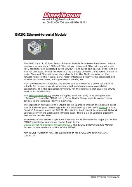
I/O pin 2.1.5.1 assignment and pin functionsEM202 pin assignment is shown below.#1 MD (MD) Input Mode selection pin#2 RST Input Reset, active high#3 P3(DTR)Input/output(output)General-purpose input/output lineData terminal ready output#4 P2(DSR)Input/output(input)General-purpose input/output lineData set ready input#5 L3(SG)Output(output)LED output 3(Green status LED)#6 L4(SR)Output(output)LED output 4(Red status LED)#7 VCC Positive power input, 5V nominal, +/- 5%, app.220mA#8 GND Ground#9 RX Input Serial receive line#10 TX Output Serial transmit line#11 P4(CTS/SEL)#12 P5(RTS/DIR)Input/output(input)Input/output(output)General-purpose input/output lineClear to send inputFull-/half-duplex selection inputGeneral-purpose input/output lineRequest to send output (full-duplex mode)Data direction control output (half-duplex mode)Line functions defined by the application firmware are shown in blueClick on one of the links provided below to learn more about EM202's I/O pins:· Serial port lines· LED lines· Power, reset, and mode selection lines©2000-2004 <strong>Tibbo</strong> Technology Inc.
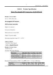
Serial port and general-purpose I/O lines#3 P3(DTR)Input/output(output)General-purpose input/output lineData terminal ready output#4 P2(DSR)Input/output(input)General-purpose input/output lineData set ready input#9 RX Serial receive line#10 TX Serial transmit line#11 P4(CTS/SEL)#12 P5(RTS/DIR)Input/output(input)Input/output(output)General-purpose input/output lineClear to send inputFull-/half-duplex selection inputGeneral-purpose input/output lineRequest to send output (full-duplex mode)Data direction control output (half-duplex mode)Line functions defined by the application firmware are shown in blueThe EM202 features a serial port (RX, TX lines) and several general-purpose I/Olines (P2*-P5). All of the above lines are of CMOS type. From the hardware point ofview, all general-purpose I/O lines can serve as inputs or outputs. Maximum loadcurrent for all CMOS lines is 10mA.Simplified structure of EM202's I/O lines is shown on the circuit diagram below. Alllines are "quasi-bidirectional" and can be viewed as open collector outputs withweak pull-up resistor. There is no explicit direction control. To "measure" an externalsignal applied to a pin the OUT line must first be set to HIGH. It is OK to drive thepin LOW externally when the pin outputs HIGH internally.The application firmware of the EM202 maps certain serial port functions onto thegeneral-purpose I/O pins- these functions are shown in blue in the table at the topof this topic. For example, P5 is a universal input/output but the applicationfirmware can be set to turn this line into the RTS output of the serial port.Therefore, depending on your application you can view P5 as a general-purpose I/Oline or specific control line of the serial port (RTS).Being of CMOS type, the serial port and I/O lines of the EM202 can be connecteddirectly to the serial port pins and I/O lines of most microcontrollers,microprocessors, etc. An interface IC** must be added to the EM202 externally ifyou want to connect the module to a "true" serial port (for example, COM port ofthe PC).Logical signals on the serial port lines of the EM202 are active LOW. TX and RX linesare high when idle, start bit is LOW, stop bit is HIGH; LOW on CTS and RTS linesmeans "transmission allowed" and HIGH means "transmission not allowed". This isstandard for CMOS-level serial ports and is exactly opposite to the signalling on theRS232 cables. Logical signals on the EM202 are inverted because standard interface©2000-2004 <strong>Tibbo</strong> Technology Inc.
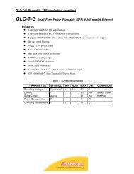
ICs** invert the signals internally too.As explained earlier, actual functionality of the I/O lines is firmware-dependent. Seeserial port and serial communications for details.* There are no lines P0 and P1. Line names were selected for naming compatibilitywith the EM100** Such as MAX232 for RS232, MAX485 for RS485, etc.LED lines#5 L3* (SG) Output LED output 3, Green status LED#6 L4* (SR) Output LED output 4, Red status LEDLine functions defined by the application firmware are shown in blueThe EM202 has two LED control lines. Both lines have the same internal structure.Each line drives one internal LED (see figure below). If you want to connect anexternal LEDs as well you may do so but we recommend using a TTL buffer elementto reduce the load on the I/O line of the EM202's internal microcontroller. Maximumload for each line without the buffer is 2mA.The firmware of the EM202 uses L3 and L4 as "status LEDs" which display variousstatus information depending on what firmware is running at the moment. Follow thelinks below to learn more about the behaviour of these LEDs under differentconditions:· SR/SG behavior in the monitor firmware.· SR/SG behavior in the application firmware.* There are no lines L1 and L2. Line names were selected for naming compatibilitywith the EM100Power, reset, and mode selection lines#7 VCC Positive power input, 5V nominal, +/- 5%, app. 230mA#8 GND Ground#2 RST Input Reset, active high#1 MD (MD) Input Mode selection pin©2000-2004 <strong>Tibbo</strong> Technology Inc.
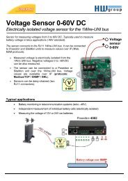
Line functions defined by the application firmware are shown in blueThe EM202 should be powered from a stabilized DS power supply with outputnominal voltage of 5V (+/- 5% tolerance). Current consumption of the EM202 isapproximately 230mA (in 100BaseT mode).Proper external reset is a must! Reset pulse should be an active HIGH. We stronglyadvise against using low-cost RC-networks and other unreliable methods ofgenerating reset pulse. Reset should be applied for as long as the power supplyvoltage is below 4.6V. We recommend using a dedicated reset IC with brownoutdetection, such as MAX810. Reset pulse length should be no less than 50ms,counting from the moment the power supply voltage exceeds 4.6V.If the EM202 is used to serve as a communications co-processor in a larger systemthat has its own CPU it is also OK to control the RST line of the EM202 through ageneral-purpose I/O pin of the "host" microcontroller. I/O pins of manymicrocontrollers default to HIGH after the powerup and this means that the resetwill be applied to the EM202 at the same time when the host microcontroller isreset. All the host microcontroller has to do is release the EM202 from reset at anappropriate time by switching the state of the I/O line to LOW.The MD line of the EM202 is used to select the operating mode of the EM202 and/orits application firmware. The reason why the pin name is shown as MD(MD) isbecause the functionality of this pin is in part hardwired and in part depends on theapplication firmware:· Hardwired functionality. When the EM202 powers up it verifies the state of theMD input. If the MD input is at HIGH the EM202 proceeds to verifying and runningthe application firmware loaded into its internal FLASH memory. If the MD input isat LOW the EM202 enters the serial upgrade mode. For more information seeMonitor.· Application firmware-dependent functionality. When the application firmwareis already running the MD line is typically used to make the EM202 enter the serialprogramming mode. For more information see serial programming.When the EM202 is used as a co-processor in a host system the MD line can be alsocontrolled by the host microcontroller. Ability to control both the RST and DS linesallows the host microcontroller to switch between the operating modes of theEM202.Built-in 2.1.5.2 LEDsThe EM202 features four built-in LEDs (shown on figure below) that are placed onthe front of the device, next to the RJ45 connector.©2000-2004 <strong>Tibbo</strong> Technology Inc.
LEDs have the following function:· Status LED (red) is internally connected to the L4(SR) LED control line.· Status LED (green) is internally connected to the L3(SG) LED control line.· Link/Data LED (green) is turned on when "live" Ethernet cable is plugged into theModule. The LED is temporarily switched off whenever an Ethernet packet isreceived.· 100BaseT LED (yellow) is turned on when the EM202 links with the hub at100Mb. The LED is off when the link is established at 10Mb.Built-in 2.1.5.3 RJ45 Ethernet connectorEthernet port of the EM202 is of 10/100BaseT type (auto-switching).Connector is of RJ45 type, pin assignment is as follows:#1 TX+#2 TX-#3 RX+#4 #5 #6 RX-#7 #8 ©2000-2004 <strong>Tibbo</strong> Technology Inc.
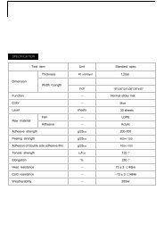
Mechanical 2.1.5.4 dimensionsL Max. 32.3 Module lengthW Max. 20.0 Module width including mounting holdersw Max. 19.0 Module width excluding mounting holdersH Max. 16.0 Module heightI Min. 4.5 Lead lengthM Min. 1.9 Height of mounting holders and solder pinst1 Aver. 2.45 Mounting holder diametert2 Aver. 1.5 Solder pin widtht3 Aver. 0.25 Solder pin thicknessp Aver. 1.27 Pin pitchs1 Aver. 29.7 Distance from device "face" to the leadss2 Aver. 6.3 Distance from leads to the center of "pockets"s3 Aver. 19.0 Distance from leads to the mounting solder pinss4 Aver. 23.0 Distance from leads to the mounting holderss5 Max. 5.0 "Pocket" lengthh1 Aver. 17.5 Distance between center lines of mounting holdersh2 Aver. 18.5 Distance between center lines of mounting solder pinsAll dimensions are in millimeters©2000-2004 <strong>Tibbo</strong> Technology Inc.
Specifications 2.1.5.5 and EM202 modificationsThe EM202 has one submodel in circulation- EM202-00.Device specifications are presented in the table below.ParameterEM202-00Ethernet interface10/100BaseT Ethernet, standard magneticsand RJ45 connector built-inSerial interface and I/O lines CMOS-level; TX, RX, and 4 additional I/O lineswith RTS, CTS, DTR, DSR implemented inapplication firmwareRouting buffers size 12Kbytes x 2*Maximum load current of I/O linesPower requirementsDevice temperature during operationOperating temperature10mAOperating relative humidity 10-90%Mechanical dimensions (excl. leads)PackingDC 5V, +/- 5%, app. 230 mA (in 100BaseTmode)+40 degrees C** (in 100BaseT mode)-10 to +70 degrees CApp. 32.5x19x15.5mmPlastic tray, 30 modules/tray* Maximum possible buffer size. Actual size may be smaller depending on howmuch RAM is "consumed" by the firmware** As measured on top of the deviceEthernet-to-serial BoardsThis part of documentation describes Ethernet-to-serial Boards supplied by <strong>Tibbo</strong>.These boards can be used for convenient evaluation and testing of <strong>Tibbo</strong> Ethernetto-serialModules. At the same time, some boards are also suitable for use inproduction devices as "faster implementation" alternatives to Modules.The following Boards are currently manufactured:· EM100-EV Evaluation Board· EM120/EM200-EV Evaluation Board· EM202-EV Ethernet-to-RS232 Boarde-mail: info@direktronik.setel: 08-52 400 700 fax: 08-520 18121©2000-2004 <strong>Tibbo</strong> Technology Inc.