Lumax 740 Family of ICDs and CRT-Ds - BIOTRONIK USA - News
Lumax 740 Family of ICDs and CRT-Ds - BIOTRONIK USA - News
Lumax 740 Family of ICDs and CRT-Ds - BIOTRONIK USA - News

Create successful ePaper yourself
Turn your PDF publications into a flip-book with our unique Google optimized e-Paper software.
<strong>BIOTRONIK</strong><br />
<strong>Lumax</strong> <strong>740</strong> <strong>IC<strong>Ds</strong></strong> & <strong>CRT</strong>-<strong>Ds</strong><br />
Technical Manual<br />
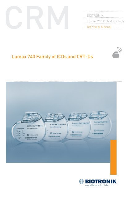
<strong>Lumax</strong> <strong>740</strong> <strong>Family</strong> <strong>of</strong> <strong>IC<strong>Ds</strong></strong> <strong>and</strong> <strong>CRT</strong>-<strong>Ds</strong>
<strong>Lumax</strong> <strong>740</strong> Technical Manual i<br />
Caution<br />
Federal (U.S.A.) law restricts this device to sale by, or on the<br />
order <strong>of</strong>, a physician.<br />
©2012 <strong>BIOTRONIK</strong>, Inc., all rights reserved.<br />
Contents<br />
1. General.............................................................................................. 1<br />
1.1 System Description...........................................................................1<br />
1.2 Indications <strong>and</strong> Usage.......................................................................4<br />
1.3 Contraindications..............................................................................4<br />
1.4 Warnings <strong>and</strong> Precautions................................................................4<br />
1.4.1 Sterilization, Storage, <strong>and</strong> H<strong>and</strong>ling............................................7<br />
1.4.2 Device Implantation <strong>and</strong> Programming.......................................7<br />
1.4.3 Lead Evaluation <strong>and</strong> Connection..................................................9<br />
1.4.4 Follow‐up Testing.......................................................................10<br />
1.4.5 Pulse Generator Explant <strong>and</strong> Disposal......................................11<br />
1.4.6 Hospital <strong>and</strong> Medical Hazards....................................................11<br />
1.4.7 Home <strong>and</strong> Occupational Hazards...............................................12<br />
1.4.8 Cellular Phones..........................................................................13<br />
1.4.9 Electronic Article Surveillance (EAS).........................................13<br />
1.4.10 Home Appliances......................................................................13<br />
1.4.11 Home Monitoring ® ...................................................................14<br />
1.5 Potential/Observed Effects <strong>of</strong> the Device on Health.......................15<br />
1.5.1 Potential Adverse Events...........................................................15<br />
1.6 Patient Selection <strong>and</strong> Treatment....................................................16<br />
1.6.1 Individualization <strong>of</strong> Treatment....................................................16<br />
1.6.2 Specific Patient Populations......................................................17<br />
1.7 Patient Counseling Information......................................................18<br />
1.8 Evaluating Prospective <strong>CRT</strong>‐D/ICD Patients..................................18<br />
2. Device Features............................................................................... 19<br />
2.1 Master Switch Behavior..................................................................19<br />
2.1.1 Enabled.......................................................................................20<br />
2.1.2 Disabled......................................................................................20<br />
2.1.3 Temporarily Active......................................................................20<br />
2.1.4 Temporarily Inactive...................................................................21<br />
2.1.5 Unknown.....................................................................................21<br />
2.2 SafeSync RF Telemetry...................................................................22<br />
2.2.1 Establishing SafeSync RF Telemetry contact:...........................22<br />
2.2.2 Economy Mode...........................................................................23<br />
2.2.3 Ending a follow‐up session........................................................24<br />
2.2.4 Switch between RF <strong>and</strong> w<strong>and</strong>....................................................25<br />
2.2.5 Power Consumption Consideration:..........................................25
ii <strong>Lumax</strong> <strong>740</strong> Technical Manual<br />
2.3 Cardiac Resynchronization Therapy (<strong>CRT</strong>).....................................26<br />
2.4 Special Features..............................................................................30<br />
2.4.1 Thoracic impedance...................................................................30<br />
2.4.2 Home Monitoring ® .....................................................................30<br />
2.4.3 Capacitor Reformation...............................................................40<br />
2.4.4 Asynchronous Pacing Modes.....................................................42<br />
2.4.5 Far‐Field IEGM for Threshold Testing (Leadless ECG)..............43<br />
2.5 Additional Device Features.............................................................43<br />
2.5.1 Real‐time IEGM Transmission ..................................................43<br />
2.5.2 Additional Programmer Functions ............................................46<br />
2.5.3 Preferences................................................................................49<br />
2.5.4 Print Manager.............................................................................55<br />
3. Sensing............................................................................................ 59<br />
3.1 Sensing (Automatic Sensitivity Control).........................................59<br />
3.1.1 Ventricular Sensitivity................................................................60<br />
3.1.2 Atrial Sensitivity in Dual‐Chamber <strong>and</strong> HF‐T <strong>IC<strong>Ds</strong></strong>...................65<br />
3.1.3 Left Ventricular Sensitivity in <strong>Lumax</strong> <strong>740</strong> HF‐T <strong>IC<strong>Ds</strong></strong>................66<br />
3.2 Far‐Field Protection........................................................................67<br />
3.2.1 Far‐Field Protection after Ventricular Sensed Events..............68<br />
3.2.2 Far‐Field Protection after Ventricular Paced Events................69<br />
3.3 Safety Pacing...................................................................................72<br />
3.4 Blanking after pacing<br />
3.4.1 Blanking after atrial pace...........................................................73<br />
3.4.2 Blank after atrial pace in the Right Ventricle............................74<br />
3.4.3 Blank after atrial pace in the Left Ventricle...............................74<br />
3.4.4 Blanking after RV pace...............................................................75<br />
3.4.5 Blanking after LV pace (HF‐T device only).................................75<br />
3.5 Discrimination after As...................................................................75<br />
4. Detection.......................................................................................... 77<br />
4.1 Ventricular Tachyarrhythmia Detection..........................................77<br />
4.1.1 Tachycardia Zone Classifications...............................................78<br />
4.1.2 Ventricular‐Only VT Detection....................................................80<br />
4.2 Ventricular Tachyarrhythmia Detection Criteria for SMART ®<br />
Detection.........................................................................................83<br />
4.2.1 Stability.......................................................................................84<br />
4.2.2 Trend AV......................................................................................84<br />
4.2.3 Sudden Onset.............................................................................85<br />
4.2.4 Rate (Interval).............................................................................86<br />
<strong>Lumax</strong> <strong>740</strong> Technical Manual iii<br />
4.2.5 Regularity (AV)............................................................................86<br />
4.2.6 Multiplicity..................................................................................87<br />
4.3 SMART ® Detection..........................................................................88<br />
4.3.1 VT Counters with SMART ® Detection On....................................90<br />
4.3.2 SMART ® Detection decision examples.......................................90<br />
4.3.3 Sustained VT Timer..................................................................107<br />
4.4 VF Detection..................................................................................107<br />
4.5 Ventricular Tachyarrhythmia Redetection....................................109<br />
4.5.1 SMART ® Redetection................................................................109<br />
4.6 Ventricular Tachyarrhythmia Termination....................................110<br />
4.6.1 Forced Termination Timer........................................................111<br />
4.7 Monitoring Zones..........................................................................113<br />
5. Tachyarrhythmia Therapy...............................................................115<br />
5.1 Antitachycardia Pacing Therapy (ATP)..........................................115<br />
5.1.1 ATP Schemes............................................................................115<br />
5.1.2 ATP One‐Shot...........................................................................120<br />
5.1.3 ATP Optimization......................................................................121<br />
5.1.4 ATP Help...................................................................................122<br />
5.1.5 Minimum ATP...........................................................................124<br />
5.2 Ventricular Shock Therapy ...........................................................124<br />
5.2.1 St<strong>and</strong>ard Biphasic Shock Waveform........................................125<br />
5.2.2 Biphasic 2 Shock Waveform.....................................................126<br />
5.2.3 Maximum Capacitor Charge Time ..........................................128<br />
5.2.4 Uncommitted Shocks (Confirmation ON by default)................128<br />
5.2.5 Committed Shocks (Confirmation OFF)...................................129<br />
5.2.6 Shock Polarity...........................................................................131<br />
5.2.7 Shock Pathway Programming for the <strong>Lumax</strong> <strong>740</strong> series ICD/<br />
<strong>CRT</strong>‐D....................................................................................133<br />
5.3 Therapy Progression.....................................................................134<br />
5.4 Post‐Shock Pacing .......................................................................135<br />
5.4.1 Shock Energy............................................................................136<br />
6. Bradycardia Therapy.......................................................................139<br />
6.1 Bradycardia Pacing Modes...........................................................139<br />
6.2 Basic <strong>and</strong> Hysteresis Rates..........................................................140<br />
6.2.1 Scan <strong>and</strong> Repetitive Rate Hysteresis.......................................141<br />
6.2.2 Night Rate.................................................................................142<br />
6.3 Dynamic AV Delay..........................................................................143<br />
6.3.1 AV Hysteresis with Scan/Repetitive .........................................145
iv <strong>Lumax</strong> <strong>740</strong> Technical Manual<br />
6.3.2 Negative AV Hysteresis.............................................................148<br />
6.3.3 Sense Compensation................................................................149<br />
6.4 I‐Opt (<strong>Lumax</strong> <strong>740</strong> DR‐T <strong>and</strong> <strong>Lumax</strong> <strong>740</strong> VR‐T DX)........................150<br />
6.5 Rate Adaptation.............................................................................150<br />
6.5.1 Maximum Sensor Rate.............................................................151<br />
6.5.2 Sensor Gain..............................................................................151<br />
6.5.3 Sensor threshold......................................................................153<br />
6.5.4 Rate Increase/Decrease...........................................................153<br />
6.6 Upper Rate Behavior.....................................................................153<br />
6.7 Mode Switching.............................................................................154<br />
6.7.1 Change <strong>of</strong> Basic Rate...............................................................156<br />
6.7.2 Post Mode Switch Rate <strong>and</strong> Duration.......................................156<br />
6.8 PMT Protection..............................................................................156<br />
6.9 LV channel programming for pacing polarity...............................157<br />
6.10 Rate Smoothing (non‐programmable)........................................158<br />
6.11 Bradycardia Noise Mode.............................................................158<br />
7. Programming Overview..................................................................161<br />
7.1 General Overview..........................................................................161<br />
7.2 Parameters Overview....................................................................162<br />
7.2.1 Bradycardia/<strong>CRT</strong> Parameters .................................................162<br />
7.2.2 Tachycardia ..............................................................................179<br />
7.2.3 Home Monitoring ® ...................................................................189<br />
7.2.4 Diagnostics...............................................................................191<br />
7.2.5 Patient......................................................................................193<br />
7.3 Conflict Manager...........................................................................201<br />
8. Implantation Testing, EP Test Functions <strong>and</strong> Follow‐up..................203<br />
8.1 P‐ <strong>and</strong> R‐Wave Measurements.....................................................203<br />
8.1.1 START (test)..............................................................................203<br />
8.1.2 Intrinsic Rhythm (test)..............................................................204<br />
8.2 Pacing Lead Impedance................................................................205<br />
8.3 Retrograde Conduction Test.........................................................207<br />
8.3.1 Measuring Retrograde Conduction..........................................207<br />
8.3.2 Programming to prevent PMT..................................................208<br />
8.4 Pacing Threshold Test...................................................................209<br />
8.5 Defibrillation Threshold Testing (DFT)..........................................211<br />
8.5.1 Induction...................................................................................213<br />
8.5.2 Shock Lead Impedance............................................................214<br />
8.5.3 Defibrillation Threshold Testing...............................................218<br />
<strong>Lumax</strong> <strong>740</strong> Technical Manual v<br />
8.5.4 Arrhythmia Induction Types.....................................................219<br />
8.5.5 Manual Therapy........................................................................222<br />
8.5.6 Emergency Shocks...................................................................223<br />
8.5.7 Non‐Invasive Programmed Stimulation Testing (NIPS)..........224<br />
9. Diagnostics .....................................................................................231<br />
9.1 Tachycardia Diagnostics................................................................231<br />
9.1.1 Recording Memory...................................................................231<br />
9.2 Bradycardia Diagnostics...............................................................236<br />
9.2.1 Timing Data..............................................................................237<br />
9.2.2 Timing Statistics.......................................................................238<br />
9.2.3 Atrial Arrhythmia Data.............................................................239<br />
9.2.4 HF Monitor................................................................................242<br />
9.2.5 48 hours....................................................................................244<br />
9.2.6 More statistics..........................................................................245<br />
10. Sterilization <strong>and</strong> Storage..............................................................251<br />
11. Implant, Follow‐up <strong>and</strong> Explantation Procedures.........................253<br />
11.1 Implant Procedure......................................................................253<br />
11.1.1 Implant Preparation...............................................................253<br />
11.1.2 Lead System Evaluation.........................................................256<br />
11.1.3 Opening the Sterile Container................................................257<br />
11.1.4 Pocket Preparation.................................................................257<br />
11.1.5 Lead to Device Connection.....................................................258<br />
11.1.6 Blind Plug Connection............................................................260<br />
11.1.7 Program the ICD/<strong>CRT</strong>‐D.........................................................260<br />
11.1.8 Implant the ICD/<strong>CRT</strong>‐D..........................................................261<br />
11.2 Follow‐up Procedures.................................................................264<br />
11.2.1 General Considerations..........................................................264<br />
11.2.2 Programmer Setup.................................................................265<br />
11.2.3 Follow‐up Assistant ...............................................................265<br />
11.2.4 Data Retrieval ........................................................................270<br />
11.2.5 IEGM Storage..........................................................................271<br />
11.2.6 Reprogramming.....................................................................272<br />
11.2.7 Manual Follow‐Up .................................................................273<br />
11.2.8 Temporary programming.......................................................276<br />
11.3 Explantation................................................................................277<br />
12. Longevity ......................................................................................279<br />
12.1 <strong>Lumax</strong> <strong>740</strong> Devices......................................................................280
vi <strong>Lumax</strong> <strong>740</strong> Technical Manual<br />
<strong>Lumax</strong> <strong>740</strong> Technical Manual vii<br />
13. Technical Specifications................................................................283<br />
Appendix A...........................................................................................295<br />
Appendix B – Known Anomalies..........................................................297<br />
Appendix C – Glossary.........................................................................299<br />
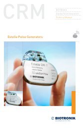
Figure 1: <strong>Lumax</strong> <strong>IC<strong>Ds</strong></strong> <strong>and</strong> <strong>CRT</strong>‐D<br />
VR‐T DR‐T/VR‐T DX HF‐T<br />
Table 1: <strong>Lumax</strong> Specifications<br />
Battery Voltage<br />
3.2 Volts<br />
Maximum Shock Energy<br />
<strong>740</strong> Models 40 Joules programmed<br />
Defibrillation Lead Ports Two DF1 (3.2 mm)<br />
Pacing Lead Ports<br />
VR‐T Models<br />
One IS‐1 (3.2 mm)<br />
DR‐T/VR‐T DX Models<br />
Two IS‐1 (3.2 mm)<br />
HF‐T Models<br />
Three IS‐1 (3.2 mm)<br />
Materials<br />
Housing<br />
Titanium<br />
Header<br />
Epoxy Resin<br />
Sealing Plug<br />
Silicone<br />
X‐ray Identification <strong>Lumax</strong> <strong>740</strong><br />
Inside Housing<br />
RH<br />
Detailed technical specifications are provided in Section 13.
viii <strong>Lumax</strong> <strong>740</strong> Technical Manual <strong>Lumax</strong> <strong>740</strong> Technical Manual 1<br />
1. General<br />
1.1 System Description<br />
The <strong>Lumax</strong> family <strong>of</strong> Implantable Cardioverter Defibrillators (<strong>IC<strong>Ds</strong></strong>)<br />
<strong>and</strong> Cardiac Resynchronization Therapy Defibrillators (<strong>CRT</strong>‐<strong>Ds</strong>) detect<br />
<strong>and</strong> treat ventricular tachyarrhythmias <strong>and</strong> provide rate adaptive<br />
bradycardia pacing support. The HF‐T version <strong>of</strong> <strong>Lumax</strong> provides<br />
Cardiac Resynchronization Therapy (<strong>CRT</strong>) through biventricular pacing.<br />
Both <strong>CRT</strong>‐<strong>Ds</strong> <strong>and</strong> <strong>IC<strong>Ds</strong></strong> detect <strong>and</strong> treat ventricular tachyarrhythmias<br />
<strong>and</strong> provide rate adaptive bradycardia pacing support. They are designed<br />
to collect diagnostic data to aid the physician’s assessment <strong>of</strong> a patient’s<br />
condition <strong>and</strong> the performance <strong>of</strong> the implanted device.<br />
The <strong>Lumax</strong> family <strong>of</strong> devices provides therapy for ventricular<br />
tachyarrhythmias with a sophisticated range <strong>of</strong> programmable<br />
anti‐tachycardia pacing (ATP), <strong>and</strong>/or defibrillation therapy features.<br />
The shock polarity <strong>and</strong> energy may be programmed to tailor the therapy<br />
to appropriately treat each patient’s tachyarrhythmias. The <strong>IC<strong>Ds</strong></strong>/<br />
<strong>CRT</strong>‐<strong>Ds</strong> provide shock therapies with programmable energies from 2 to<br />
40 joules.<br />
The <strong>Lumax</strong> family <strong>of</strong> <strong>IC<strong>Ds</strong></strong>/<strong>CRT</strong>‐<strong>Ds</strong> includes the following members:<br />
• <strong>Lumax</strong> HF‐T ‐ provides three chamber rate‐adaptive bradycardia<br />
pacing support including biventricular pacing via the right <strong>and</strong><br />
left ventricular pacing lead. The <strong>CRT</strong>‐D uses the atrial <strong>and</strong> right<br />
ventricular sensing/pacing leads to provide enhanced atrial <strong>and</strong><br />
ventricular tachyarrhythmia discrimination through <strong>BIOTRONIK</strong>’s<br />
SMART Detection algorithm. In addition, <strong>Lumax</strong> HF‐T also has<br />
<strong>BIOTRONIK</strong>’s Home Monitoring system. The Home Monitoring<br />
System enables automatic exchange <strong>of</strong> information about a patient’s<br />
cardiac status from the implanted device to the physician remotely.<br />
• <strong>Lumax</strong> DR‐T ‐ provides dual chamber rate adaptive bradycardia<br />
pacing support. The ICD uses atrial <strong>and</strong> ventricular sensing/pacing<br />
leads to provide enhanced atrial <strong>and</strong> ventricular tachyarrhythmia<br />
discrimination through <strong>BIOTRONIK</strong>’s SMART Detection ® algorithm.<br />
In addition, it also has <strong>BIOTRONIK</strong>’s Home Monitoring ® system.<br />
The Home Monitoring System enables automatic exchange <strong>of</strong><br />
information about a patient’s cardiac status from the implanted<br />
device to the physician remotely.
2 <strong>Lumax</strong> <strong>740</strong> Technical Manual <strong>Lumax</strong> <strong>740</strong> Technical Manual 3<br />
• <strong>Lumax</strong> VR‐T ‐ provides single chamber rate adaptive bradycardia<br />
pacing support as well as tachyarrhythmia detection <strong>and</strong> therapy.<br />
In addition, it also has <strong>BIOTRONIK</strong>’s Home Monitoring system.<br />
The Home Monitoring System enables automatic exchange <strong>of</strong><br />
information about a patient’s cardiac status from the implanted<br />
device to the physician remotely.<br />
• <strong>Lumax</strong> VR‐T DX – provides ventricular rate adaptive bradycardia<br />
pacing support that can include atrial tracking with a single pass ICD<br />
lead <strong>and</strong> also has <strong>BIOTRONIK</strong>’s Home Monitoring system. The ICD<br />
uses a single atrial <strong>and</strong> ventricular sensing/pacing lead to provide<br />
enhanced atrial <strong>and</strong> ventricular tachyarrhythmia discrimination<br />
through <strong>BIOTRONIK</strong>’s SMART Detection ® algorithm. The Home<br />
Monitoring System enables automatic exchange <strong>of</strong> information<br />
about a patient’s cardiac status from the implanted device to the<br />
physician remotely.<br />
The <strong>740</strong> designation for each <strong>of</strong> the above‐described models denote the<br />
maximum programmable shock energy <strong>of</strong> 40 joules.<br />
The <strong>Lumax</strong> <strong>740</strong> models also feature a third programmable shock path<br />
for delivery <strong>of</strong> defibrillation/cardioversion shocks. The shock path is<br />
programmable between the different shock coils (SVC/RV) <strong>and</strong>/or the<br />
device housing. Section 5.2.7 provides further details on the available<br />
shock configurations. The <strong>Lumax</strong> <strong>740</strong> HF‐T models also feature an<br />
additional left ventricular (LV) pacing polarity for HF‐T devices from<br />
LV‐tip to housing (unipolar).<br />
Additionally, the <strong>Lumax</strong> <strong>740</strong> models feature Ventricular Capture Control <strong>of</strong><br />
ventricular pacing thresholds. This feature is separately programmable<br />
for the right (RV) <strong>and</strong> left (LV) ventricle. Section 7.2.1.12 provides further<br />
details.<br />
The <strong>Lumax</strong> <strong>740</strong> models also provide RF Telemetry (SafeSync) to ease<br />
implantation <strong>and</strong> follow‐up procedures. In addition, these devices<br />
include Thoracic Impedance monitoring <strong>and</strong> Atrial NIPS that can be<br />
used for an EP study to induce an arrhythmia or to burst pace a patient<br />
out <strong>of</strong> a stable tachyarrhythmia.<br />
<strong>Lumax</strong> <strong>740</strong> models will present with automatic Far‐Field IEGM to provide<br />
a means to generate the surface ECG‐like signal without the need for<br />
attaching the surface electrodes to the patients.<br />
All <strong>Lumax</strong> models have two DF‐1 defibrillation/cardioversion ports.<br />
Additionally, the <strong>Lumax</strong> HF‐T models have three IS‐1 pacing/sensing<br />
header ports, the <strong>Lumax</strong> DR‐T <strong>and</strong> <strong>Lumax</strong> VR‐T DX models have two<br />
IS‐1 pacing/sensing header ports <strong>and</strong> the <strong>Lumax</strong> VR‐T models have only<br />
one IS‐1 pacing/sensing header port. IS‐1 refers to the international<br />
st<strong>and</strong>ard whereby leads <strong>and</strong> generators from different manufacturers<br />
are assured a basic fit [Reference ISO 5841‐3:1992]. DF‐1 refers to the<br />
international st<strong>and</strong>ard for defibrillation lead connectors [Reference<br />
ISO 11318:1993].<br />
External devices that interact with <strong>and</strong> test the implantable devices are<br />
also part <strong>of</strong> the ICD/<strong>CRT</strong>‐D System. These external devices include the<br />
ICS 3000 Programming <strong>and</strong> the Implant Module System Analyzer or<br />
Pacing System Analyzer for acute lead testing. The ICS 3000 or Renamic<br />
programmer is used to interrogate <strong>and</strong> program the ICD/<strong>CRT</strong>‐<strong>Ds</strong>.<br />
The <strong>Lumax</strong> <strong>740</strong> models also feature SafeSync Telemetry (RF‐Telemetry)<br />
via the Renamic programmer or the ICS 3000 programmer in<br />
combination with the SafeSync Module (an external communication<br />
module).<br />
<strong>BIOTRONIK</strong> conducted the TRUST study to evaluate the safety <strong>and</strong><br />
effectiveness <strong>of</strong> Home Monitoring. With the TRUST study, <strong>BIOTRONIK</strong> was<br />
able to show the following with regards to Home Monitoring:<br />
• <strong>BIOTRONIK</strong> Home Monitoring information may be used as a<br />
replacement for device interrogation during in‐<strong>of</strong>fice follow‐up<br />
visits.<br />
• A strategy <strong>of</strong> care using <strong>BIOTRONIK</strong> Home Monitoring with <strong>of</strong>fice<br />
visits when needed has been shown to extend the time between<br />
routine, scheduled in‐<strong>of</strong>fice follow‐ups <strong>of</strong> <strong>BIOTRONIK</strong> implantable<br />
devices in many patients. Home Monitoring data is helpful in<br />
determining the need for additional in‐<strong>of</strong>fice follow‐up.<br />
• <strong>BIOTRONIK</strong> Home Monitoring‐patients—who are followed remotely<br />
with <strong>of</strong>fice visits when needed—have been shown to have similar<br />
numbers <strong>of</strong> strokes, invasive procedures <strong>and</strong> deaths as patients<br />
followed with conventional in‐<strong>of</strong>fice follow‐ups.<br />
• <strong>BIOTRONIK</strong> Home Monitoring provides early detection <strong>of</strong><br />
arrhythmias.<br />
• <strong>BIOTRONIK</strong> Home Monitoring provides early detection <strong>of</strong> silent,<br />
asymptomatic arrhythmias.<br />
• Automatic early detection <strong>of</strong> arrhythmias <strong>and</strong> device system<br />
anomalies by <strong>BIOTRONIK</strong> Home Monitoring allows for earlier<br />
intervention than conventional in‐<strong>of</strong>fice follow‐ups.<br />
• <strong>BIOTRONIK</strong> Home Monitoring allows for improved access to patient<br />
device data compared to conventional in‐<strong>of</strong>fice follow‐ups since<br />
device interrogation is automatically scheduled at regular intervals.
4 <strong>Lumax</strong> <strong>740</strong> Technical Manual <strong>Lumax</strong> <strong>740</strong> Technical Manual 5<br />
1.2 Indications <strong>and</strong> Usage<br />
The <strong>Lumax</strong> <strong>CRT</strong>‐<strong>Ds</strong> are indicated for use in patients with all <strong>of</strong> the<br />
following conditions:<br />
• Indicated for ICD therapy<br />
• Receiving optimized <strong>and</strong> stable Congestive Heart Failure (CHF) drug<br />
therapy<br />
• Symptomatic CHF (NYHA Class III/IV <strong>and</strong> LVEF ≤35%); <strong>and</strong><br />
• Intraventricular conduction delay (QRS duration ≥130 ms)<br />
The <strong>Lumax</strong> Implantable Cardioverter Defibrillators (<strong>IC<strong>Ds</strong></strong>) <strong>and</strong> Cardiac<br />
Resynchronization Therapy Defibrillators (<strong>CRT</strong>‐<strong>Ds</strong>) are intended to<br />
provide ventricular anti‐tachycardia pacing <strong>and</strong> ventricular defibrillation,<br />
for automated treatment <strong>of</strong> life‐threatening ventricular arrhythmias.<br />
1.3 Contraindications<br />
The <strong>Lumax</strong> devices are contraindicated for use in patients with the<br />
following conditions:<br />
• Patients whose ventricular tachyarrhythmias may have transient or<br />
reversible causes such as:<br />
--<br />
Acute myocardial infarction<br />
--<br />
Digitalis intoxication<br />
--<br />
Drowning<br />
--<br />
Electrocution<br />
--<br />
Electrolyte imbalance<br />
--<br />
Hypoxia<br />
--<br />
Sepsis<br />
• Patients with incessant ventricular fibrillation (VF) <strong>and</strong> ventricular<br />
tachycardia (VT)<br />
• Patients whose only disorder is brady arrhythmias or atrial<br />
arrhythmias<br />
1.4 Warnings <strong>and</strong> Precautions<br />
MRI (Magnetic Resonance Imaging) ‐ Do not expose a patient to MRI<br />
device scanning. Strong magnetic fields may damage the device <strong>and</strong><br />
cause injury to the patient.<br />
Electrical Isolation ‐ To prevent inadvertent arrhythmia induction,<br />
electrically isolate the patient during the implant procedure from<br />
potentially hazardous leakage currents.<br />
Left Ventricular Lead Systems – <strong>BIOTRONIK</strong> <strong>CRT</strong>‐<strong>Ds</strong> may be implanted<br />
with any legally marketed, compatible LV lead. Compatibility is defined<br />
as:<br />
• IS‐1 pacing connector<br />
• Active or passive fixation technology<br />
• Insertion <strong>and</strong> withdrawal forces as specified by ISO 5841‐3 (IS‐1)<br />
The following LV leads were evaluated in the OPTION <strong>CRT</strong>/ATx study with<br />
<strong>BIOTRONIK</strong>’s <strong>CRT</strong>‐<strong>Ds</strong>:<br />
• Guidant‐EASYTRAK ® IS‐1 Lead<br />
• Guidant‐EASYTRAK LV‐1 Lead<br />
• Guidant‐EASYTRAK 2 Lead<br />
• Guidant‐EASYTRAK 3 Lead<br />
• Medtronic‐Attain ® OTW Lead<br />
• St. Jude‐Aescula Lead<br />
• St. Jude‐QuickSite ® Lead<br />
• Biomec‐Myopore Epicardial Lead<br />
• Medtronic‐Epicardial 5071 Lead<br />
• Medtronic‐CapSure ® EPI Lead<br />
• <strong>BIOTRONIK</strong>‐ELC 54‐UP Lead<br />
The following LV leads were bench tested for compatibility with<br />
<strong>BIOTRONIK</strong>’s <strong>CRT</strong>‐<strong>Ds</strong>:<br />
• Guidant EASYTRAK 4512 (unipolar) Lead<br />
• Guidant EASYTRAK 4513 (bipolar) Lead<br />
• Guidant EASYTRAK 3 4525 (bipolar) Lead<br />
• Medtronic Attain OTW 4193 (unipolar) Lead<br />
• Medtronic Attain OTW 4194 (bipolar) Lead<br />
• Medtronic Attain LV 2187 (unipolar) Lead<br />
• St. Jude Medical QuickSite 1056K (unipolar) Lead<br />
• ELA SITUS ® OTW (unipolar) Lead<br />
• <strong>BIOTRONIK</strong> Corox OTW 75‐UP Steroid #346542 (unipolar) Lead<br />
• <strong>BIOTRONIK</strong> Corox+ LV‐H 75‐BP #341885 (bipolar) Lead
6 <strong>Lumax</strong> <strong>740</strong> Technical Manual <strong>Lumax</strong> <strong>740</strong> Technical Manual 7<br />
ICD Lead Systems – <strong>BIOTRONIK</strong> <strong>IC<strong>Ds</strong></strong>/<strong>CRT</strong>‐<strong>Ds</strong> maybe implanted with<br />
any legally marketed, compatible ICD lead. Compatibility is defined as:<br />
• IS‐1 pacing <strong>and</strong> sensing connector(s)<br />
• DF‐1 shock coil connector(s)<br />
• Integrated or dedicated bipolar pacing <strong>and</strong> sensing configuration<br />
• Active or passive fixation technology<br />
• Single or dual defibrillation shock coil (s)<br />
• High energy shock accommodation up to 40 joules<br />
• Insertion <strong>and</strong> withdrawal forces as specified by ISO 5841‐3 (IS‐1)<br />
<strong>and</strong> ISO 11318:1993 (E) DF‐1<br />
The following leads were evaluated in a retrospective study with<br />
<strong>BIOTRONIK</strong>’s <strong>IC<strong>Ds</strong></strong>/<strong>CRT</strong>‐<strong>Ds</strong>:<br />
• Medtronic Sprint Lead 6932<br />
• Medtronic Sprint Lead 6943<br />
• Medtronic Sprint Quattro Lead 6944<br />
• Medtronic Transvene RV Lead 6936<br />
• St. Jude (Ventritex) TVLTM‐ ADX Lead 1559<br />
• St. Jude SPL ® SP02 Lead<br />
• Guidant ENDOTAK ® DSP Lead<br />
• Guidant ENDOTAK Endurance EZ Lead, ENDOTAK Reliance Lead<br />
• Guidant (Intermedics) Lead 497‐24.<br />
The following leads were bench tested for compatibility with <strong>BIOTRONIK</strong>’s<br />
<strong>IC<strong>Ds</strong></strong>/<strong>CRT</strong>‐<strong>Ds</strong>:<br />
• Guidant ENDOTAK Endurance Lead “CPI 0125”<br />
• Guidant ENDOTAK Reliance Lead 0148<br />
• Medtronic Sprint Lead 6932<br />
• Medtronic Sprint Lead 6942<br />
• Medtronic Sprint Lead 6943<br />
• Medtronic Sprint Lead6945<br />
• Medtronic Sprint Quattro Lead 6944<br />
• St. Jude Riata ® Lead 1571/65<br />
• St. Jude SPL SPO1 Lead.<br />
Resuscitation Availability ‐ Do not perform induction testing unless<br />
an alternate source <strong>of</strong> patient defibrillation such as an external<br />
defibrillator is readily available. In order to implant the ICD/<strong>CRT</strong>‐D<br />
system, it is necessary to induce <strong>and</strong> convert the patient’s ventricular<br />
tachyarrhythmias.<br />
Unwanted Shocks – Always program ICD Therapy to OFF prior to<br />
h<strong>and</strong>ling the device to prevent the delivery <strong>of</strong> serious shocks to the<br />
patient or the person h<strong>and</strong>ling the device during the implant procedure.<br />
Rate‐Adaptive Pacing – Use rate‐adaptive pacing with care in patients<br />
unable to tolerate increased pacing rates.<br />
Blanking after RV pace – Extending this value too long may lead to<br />
delays in arrhythmia detection. Consult Technical Services prior to<br />
extending this value.<br />
Short Pacing Intervals – Use <strong>of</strong> short pacing intervals (high pacing<br />
rates) with long atrial <strong>and</strong>/or ventricular refractory periods may<br />
result in intermittent asynchronous pacing <strong>and</strong>, therefore, may be<br />
contraindicated in some patients.<br />
1.4.1 Sterilization, Storage, <strong>and</strong> H<strong>and</strong>ling<br />
Device Packaging ‐ Do not use the device if the device’s packaging is<br />
wet, punctured, opened or damaged because the integrity <strong>of</strong> the sterile<br />
packaging may be compromised. Return the device to <strong>BIOTRONIK</strong>.<br />
Re‐sterilization ‐ Do not re‐sterilize <strong>and</strong> re‐implant explanted devices.<br />
Storage (temperature) ‐ Store the device between 5° to 45°C (41°‐113°F)<br />
because temperatures outside this range could damage the device.<br />
Storage (magnets) ‐ To avoid damage to the device, store the device in a<br />
clean area, away from magnets, kits containing magnets, <strong>and</strong> sources <strong>of</strong><br />
electromagnetic interference (EMI).<br />
Temperature Stabilization ‐ Allow the device to reach room temperature<br />
before programming or implanting the device because temperature<br />
extremes may affect initial device function.<br />
Use Before Date ‐ Do not implant the device after the USE BEFORE<br />
DATE because the device may have reduced longevity.<br />
1.4.2 Device Implantation <strong>and</strong> Programming<br />
Blind Plug ‐ A blind plug must be inserted <strong>and</strong> firmly connected into any<br />
unused header port to prevent chronic fluid influx <strong>and</strong> possible shunting<br />
<strong>of</strong> high energy therapy.
8 <strong>Lumax</strong> <strong>740</strong> Technical Manual <strong>Lumax</strong> <strong>740</strong> Technical Manual 9<br />
Capacitor Reformation ‐ Infrequent charging <strong>of</strong> the high voltage<br />
capacitors may extend the charge times <strong>of</strong> the ICD/<strong>CRT</strong>‐D. The<br />
capacitors are reformed automatically at least every 90 days. For further<br />
information, please refer to Section 2.4.3, Capacitor Reforming.<br />
Connector Compatibility – ICD/<strong>CRT</strong>‐D <strong>and</strong> lead system compatibility<br />
should be confirmed prior to the implant procedure. Consult your<br />
<strong>BIOTRONIK</strong> representative regarding lead/pulse generator compatibility<br />
prior to the implantation <strong>of</strong> an ICD/<strong>CRT</strong>‐D system. For further<br />
information, please refer to “Appendix A”.<br />
ERI (Elective Replacement Indicator) ‐ Upon reaching ERI, the battery<br />
has sufficient energy remaining to continue monitoring for at least three<br />
months <strong>and</strong> to deliver a minimum <strong>of</strong> six maximum energy shocks. After<br />
this period (EOS), all tachyarrhythmia detection <strong>and</strong> therapy is disabled.<br />
Bradycardia functions are still active at programmed values until the<br />
battery voltage drops below 1.75 volts.<br />
Magnets ‐ Positioning <strong>of</strong> a magnet over the ICD/<strong>CRT</strong>‐D will suspend<br />
tachycardia detection <strong>and</strong> treatment. The minimum magnet strength<br />
required to suspend tachycardia treatment is 1.8 mT. When the magnet<br />
strength decreases to less than 1 mT, the reed contact is reopened.<br />
Programmed Parameters – Program the device parameters to<br />
appropriate values based on the patient’s specific arrhythmias <strong>and</strong><br />
condition.<br />
Programmers ‐ Use only <strong>BIOTRONIK</strong> ICS 3000 or Renamic programmers<br />
to communicate with the device.<br />
Sealing System ‐ Failure to properly insert the torque wrench into the<br />
perforation at an angle perpendicular to the connector receptacle may<br />
result in damage to the sealing system <strong>and</strong> its self‐sealing properties.<br />
Defibrillation Threshold ‐ Be aware that changes in the patient’s<br />
condition, drug regimen, <strong>and</strong> other factors may change the defibrillation<br />
threshold (DFT) which may result in non‐conversion <strong>of</strong> the arrhythmia<br />
post‐operatively. Successful conversion <strong>of</strong> ventricular fibrillation or<br />
ventricular tachycardia during arrhythmia conversion testing is no<br />
assurance that conversion will occur post‐operatively.<br />
Manual Shocks – User‐comm<strong>and</strong>ed shocks may be withheld if the ICD/<br />
<strong>CRT</strong>‐D is already busy processing a manual comm<strong>and</strong> or the Battery<br />
Status is low.<br />
Charge Time ‐ When preparing a high energy shock the charge circuit<br />
stops charging the capacitors after 20 seconds, <strong>and</strong> delivers the stored<br />
energy as shock therapy. After the device reaches ERI the stored energy<br />
may be less than the maximum programmable energy for each shock.<br />
Programming W<strong>and</strong> Separation Distance – The w<strong>and</strong> (with magnet)<br />
must not be placed closer than 2 cm to the device (implanted or out <strong>of</strong><br />
the box). Programming w<strong>and</strong> (with magnet) distance closer than 2 cm<br />
may damage the device.<br />
Shipment Mode – The shipment mode is a factory set mode that<br />
controls the charge current <strong>of</strong> automatic capacitor reformations. This<br />
mode controls the charge current to avoid temporary low battery<br />
readings. The shipment mode is automatically deactivated as soon as<br />
electrophysiological tests (e.g., Impedance measurement) are initiated<br />
by the programmer. To ensure delivery <strong>of</strong> programmed shock energy,<br />
make sure shipment mode is disabled prior to completion <strong>of</strong> implant<br />
procedure.<br />
Shock Therapy Confirmation – Programming CONFIRMATION to OFF<br />
may increase the incidence <strong>of</strong> the ICD/<strong>CRT</strong>‐D delivering inappropriate<br />
shocks.<br />
Shock Impedance ‐ If the shock impedance is less than twenty‐five<br />
ohms (25 Ω), reposition the lead system to allow a greater distance<br />
between the electrodes. Never implant the device with a lead system<br />
that has measured shock impedance <strong>of</strong> less than twenty‐five ohms<br />
(25 Ω). Damage to the device may result.<br />
Negative AV Hysteresis – This feature insures ventricular pacing, a<br />
technique which has been used in patients with hypertrophic obstructive<br />
cardiomyopathy (HOCM) with normal AV conduction in order to replace<br />
intrinsic ventricular activation. No clinical study was conducted to<br />
evaluate this feature, <strong>and</strong> there is conflicting evidence regarding the<br />
potential benefit <strong>of</strong> ventricular pacing therapy for HOCM patients.<br />
In addition, there is evidence with other patient groups to suggest<br />
that inhibiting the intrinsic ventricular activation sequence by right<br />
ventricular pacing may impair hemodynamic function <strong>and</strong>/or survival.<br />
1.4.3 Lead Evaluation <strong>and</strong> Connection<br />
Capping Leads ‐ If a lead is ab<strong>and</strong>oned rather than removed, it must<br />
be capped to ensure that it is not a pathway for currents to or from the<br />
heart.<br />
Gripping Leads ‐ Do not grip the lead with surgical instruments or use<br />
excessive force or surgical instruments to insert a stylet into a lead.<br />
Kinking Leads ‐ Do not kink leads. This may cause additional stress on<br />
the leads that can result in damage to the lead.<br />
Liquid Immersion ‐ Do not immerse leads in mineral oil, silicone oil, or<br />
any other liquid.
10 <strong>Lumax</strong> <strong>740</strong> Technical Manual <strong>Lumax</strong> <strong>740</strong> Technical Manual 11<br />
Short Circuit ‐ Ensure that none <strong>of</strong> the lead electrodes are in contact (a<br />
short circuit) during delivery <strong>of</strong> shock therapy as this may cause current<br />
to bypass the heart or cause damage to the ICD/<strong>CRT</strong>‐D system.<br />
Far‐Field Sensing ‐ <strong>of</strong> signals from the atrium in the ventricular<br />
channel or ventricular signals in the atrial channel should be avoided<br />
by appropriate lead placement, programming <strong>of</strong> pacing/sensing<br />
parameters, <strong>and</strong> maximum sensitivity settings. If it is necessary to<br />
modify the Far Field Blanking parameter, the parameter should be<br />
lengthened only long enough to eliminate far‐field sensing as evidenced<br />
on the IEGMs. Extending the parameter unnecessarily may cause under<br />
sensing <strong>of</strong> actual atrial or ventricular events.<br />
Suturing Leads ‐ Do not suture directly over the lead body as this<br />
may cause structural damage. Use the appropriate suture sleeve to<br />
immobilize the lead <strong>and</strong> protect it against damage from ligatures.<br />
Tricuspid Valve Bioprosthesis ‐ Use ventricular transvenous leads with<br />
caution in patients with a tricuspid valvular bioprosthesis.<br />
Setscrew Adjustment – Back‐<strong>of</strong>f the setscrew(s) prior to insertion <strong>of</strong><br />
lead connector(s) as failure to do so may result in damage to the lead(s),<br />
<strong>and</strong>/or difficulty connecting lead(s).<br />
Cross Threading Setscrew(s) – To prevent cross threading the<br />
setscrew(s), do not back the setscrew(s) completely out <strong>of</strong> the threaded<br />
hole. Leave the torque wrench in the slot <strong>of</strong> the setscrew(s) while the<br />
lead is inserted.<br />
Tightening Setscrew(s) – Do not over tighten the setscrew(s). Use only<br />
the <strong>BIOTRONIK</strong> supplied torque wrench.<br />
Sealing System – Be sure to properly insert the torque wrench into the<br />
perforation perpendicular to the connector receptacle. Failure to do so<br />
may result in damage to the plug <strong>and</strong> its self‐sealing properties.<br />
1.4.4 Follow‐up Testing<br />
Defibrillation Threshold ‐ Be aware that changes in the patient’s<br />
condition, drug regimen, <strong>and</strong> other factors may change the defibrillation<br />
threshold (DFT), which may result in non‐conversion <strong>of</strong> the arrhythmia<br />
post‐operatively. Successful conversion <strong>of</strong> ventricular fibrillation or<br />
ventricular tachycardia during arrhythmia conversion testing is no<br />
assurance that conversion will occur post‐operatively.<br />
Resuscitation Availability ‐ Ensure that an external defibrillator <strong>and</strong><br />
medical personnel skilled in cardiopulmonary resuscitation (CPR) are<br />
present during post‐implant device testing should the patient require<br />
external rescue.<br />
Safe Program – Within the EP Test screen, pressing the “Safe Program”<br />
key on the programmer or programmer head immediately sends the<br />
safe program to the ICD/<strong>CRT</strong>‐D.<br />
1.4.5 Pulse Generator Explant <strong>and</strong> Disposal<br />
Device Incineration – Never incinerate the ICD/<strong>CRT</strong>‐D due to the<br />
potential for explosion. The ICD/<strong>CRT</strong>‐D must be explanted prior to<br />
cremation.<br />
Explanted Devices – Return all explanted devices to <strong>BIOTRONIK</strong>.<br />
Unwanted Shocks – Always program ICD Therapy to OFF prior to<br />
h<strong>and</strong>ling the device to prevent the delivery <strong>of</strong> serious shocks to the<br />
patient or the person h<strong>and</strong>ling the device during the procedure.<br />
1.4.6 Hospital <strong>and</strong> Medical Hazards<br />
Electromagnetic interference (EMI) ‐ signals present in hospital <strong>and</strong><br />
medical environments may affect the function <strong>of</strong> any ICD/<strong>CRT</strong>‐D or<br />
pacemaker. The ICD/<strong>CRT</strong>‐D is designed to selectively filter out EMI<br />
noise. However, due to the variety <strong>of</strong> EMI signals, absolute protection<br />
from EMI is not possible with this or any other ICD/<strong>CRT</strong>‐D.<br />
The ICD/<strong>CRT</strong>‐D system should have detection <strong>and</strong> therapy disabled<br />
(OFF) prior to performing any <strong>of</strong> the following medical procedures. In<br />
addition, the ICD/<strong>CRT</strong>‐D should be checked after the procedures to<br />
assure proper programming:<br />
Diathermy ‐ Diathermy therapy is not recommended for ICD/<strong>CRT</strong>‐D<br />
patients due to possible heating effects <strong>of</strong> the pulse generator <strong>and</strong> at<br />
the implant site. If diathermy therapy must be used, it should not be<br />
applied in the immediate vicinity <strong>of</strong> the pulse generator or lead system.<br />
Electrocautery ‐ Electrosurgical cautery could induce ventricular<br />
arrhythmias <strong>and</strong>/or fibrillation, or may cause device malfunction or<br />
damage. If use <strong>of</strong> electrocautery is necessary, the current path <strong>and</strong><br />
ground plate should be kept as far away from the pulse generator <strong>and</strong><br />
leads as possible (at least 6 inches (15 cm)).<br />
External Defibrillation ‐ The device is protected against energy normally<br />
encountered from external defibrillation. However, any implanted device<br />
may be damaged by external defibrillation procedures. In addition,<br />
external defibrillation may also result in permanent myocardial damage
12 <strong>Lumax</strong> <strong>740</strong> Technical Manual <strong>Lumax</strong> <strong>740</strong> Technical Manual 13<br />
at the electrode‐tissue interface as well as temporary or permanent<br />
elevated pacing thresholds. When possible, observe the following<br />
precautions:<br />
• Position the adhesive electrodes or defibrillation paddles <strong>of</strong> the<br />
external defibrillator anterior‐posterior or along a line perpendicular<br />
to the axis formed by the implanted device <strong>and</strong> the heart.<br />
• Set the energy to a level not higher than is required to achieve<br />
defibrillation.<br />
• Place the paddles as far as possible away from the implanted device<br />
<strong>and</strong> lead system.<br />
• After delivery <strong>of</strong> an external defibrillation shock, interrogate the<br />
ICD/<strong>CRT</strong>‐D to confirm device status <strong>and</strong> proper function.<br />
Lithotripsy ‐ Lithotripsy may damage the ICD/<strong>CRT</strong>‐D. If lithotripsy must<br />
be used, avoid focusing near the ICD/<strong>CRT</strong>‐D implant site.<br />
MRI (Magnetic Resonance Imaging) ‐ Do not expose a patient to MRI<br />
device scanning. Strong magnetic fields may damage the device <strong>and</strong><br />
cause injury to the patient.<br />
Radiation ‐ High radiation sources such as cobalt 60 or gamma<br />
radiation should not be directed at the pulse generator. If a patient<br />
requires radiation therapy in the vicinity <strong>of</strong> the pulse generator, place<br />
lead shielding over the device to prevent radiation damage <strong>and</strong> confirm<br />
its function after treatment.<br />
Radio Frequency Ablation ‐ Prior to performing an ablation procedure,<br />
deactivate the ICD/<strong>CRT</strong>‐D during the procedure. Avoid applying ablation<br />
energy near the implanted lead system whenever possible.<br />
1.4.7 Home <strong>and</strong> Occupational Hazards<br />
Patients should be directed to avoid devices that generate strong<br />
electromagnetic interference (EMI) or magnetic fields. EMI could cause<br />
device malfunction or damage resulting in non‐detection or delivery <strong>of</strong><br />
unneeded therapy. Moving away from the source or turning it <strong>of</strong>f will<br />
usually allow the ICD/<strong>CRT</strong>‐D to return to its normal mode <strong>of</strong> operation.<br />
The following equipment (<strong>and</strong> similar devices) may affect normal ICD/<br />
<strong>CRT</strong>‐D operation: electric arc or resistance welders, electric melting<br />
furnaces, radio/television <strong>and</strong> radar transmitters, power‐generating<br />
facilities, high‐voltage transmission lines, <strong>and</strong> electrical ignition<br />
systems (<strong>of</strong> gasoline‐powered devices) if protective hoods, shrouds, etc.,<br />
are removed.<br />
1.4.8 Cellular Phones<br />
Testing has indicated there may be a potential interaction between<br />
cellular phones <strong>and</strong> <strong>BIOTRONIK</strong> ICD/<strong>CRT</strong>‐D systems. Potential effects<br />
may be due to either the cellular phone signal or the magnet within the<br />
telephone <strong>and</strong> may include inhibition <strong>of</strong> therapy when the telephone is<br />
within 6 inches (15 centimeters) <strong>of</strong> the ICD/<strong>CRT</strong>‐D, when the ICD/<strong>CRT</strong>‐D<br />
is programmed to st<strong>and</strong>ard sensitivity.<br />
Patients having an implanted <strong>BIOTRONIK</strong> ICD/<strong>CRT</strong>‐D who operate a<br />
cellular telephone should:<br />
• Maintain a minimum separation <strong>of</strong> 6 inches (15 centimeters)<br />
between a h<strong>and</strong>‐held personal cellular telephone <strong>and</strong> the implanted<br />
device.<br />
• Set the telephone to the lowest available power setting, if possible.<br />
• Patients should hold the phone to the ear opposite the side <strong>of</strong> the<br />
implanted device. Patients should not carry the telephone in a<br />
breast pocket or on a belt over or within 6 inches (15 centimeters)<br />
<strong>of</strong> the implanted device as some telephones emit signals when they<br />
are turned ON, but not in use (i.e., in the listen or st<strong>and</strong>‐by mode).<br />
Store the telephone in a location opposite the side <strong>of</strong> implant.<br />
Based on results to date, adverse effects resulting from interactions<br />
between cellular telephones <strong>and</strong> implanted <strong>IC<strong>Ds</strong></strong>/<strong>CRT</strong>‐<strong>Ds</strong> have been<br />
transitory. The potential adverse effects could include inhibition or<br />
delivery <strong>of</strong> additional therapies. If electromagnetic interference (EMI)<br />
emitting from a telephone does adversely affect an implanted ICD/<br />
<strong>CRT</strong>‐D, moving the telephone away from the immediate vicinity <strong>of</strong> the<br />
ICD/<strong>CRT</strong>‐D should restore normal operation. A recommendation to<br />
address every specific interaction <strong>of</strong> EMI with implanted <strong>IC<strong>Ds</strong></strong>/<strong>CRT</strong>‐<strong>Ds</strong> is<br />
not possible due to the disparate nature <strong>of</strong> EMI.<br />
1.4.9 Electronic Article Surveillance (EAS)<br />
Equipment such as retail theft prevention systems may interact with<br />
pulse generators. Patients should be advised to walk directly through<br />
<strong>and</strong> not to remain near an EAS system longer than necessary.<br />
1.4.10 Home Appliances<br />
Home appliances normally do not affect ICD/<strong>CRT</strong>‐D operation if the<br />
appliances are in proper working condition <strong>and</strong> correctly grounded <strong>and</strong><br />
shielded. There have been reports <strong>of</strong> the interaction <strong>of</strong> electric tools or<br />
other external devices (e.g. electric drills, older models <strong>of</strong> microwave<br />
ovens, electric razors, etc.) with <strong>IC<strong>Ds</strong></strong>/<strong>CRT</strong>‐<strong>Ds</strong> when they are placed in<br />
close proximity to the device.
14 <strong>Lumax</strong> <strong>740</strong> Technical Manual <strong>Lumax</strong> <strong>740</strong> Technical Manual 15<br />
1.4.11 Home Monitoring ®<br />
<strong>BIOTRONIK</strong>’s Home Monitoring system is designed to notify clinicians in<br />
less than 24 hours <strong>of</strong> changes to the patient’s condition or status <strong>of</strong> the<br />
implanted device. Updated data may not be available if:<br />
• The patient’s CardioMessenger is <strong>of</strong>f or damaged <strong>and</strong> is not able to<br />
connect to the Home Monitoring system through an active telephone<br />
link<br />
• The CardioMessenger cannot establish a connection to the<br />
implanted device<br />
• The telephone <strong>and</strong>/or Internet connection do not operate properly<br />
• The Home Monitoring Service Center is <strong>of</strong>f‐line (upgrades are<br />
typically completed in less than 24 hours)<br />
Patient’s Ability ‐ Use <strong>of</strong> the Home Monitoring system requires the<br />
patient <strong>and</strong>/or caregiver to follow the system instructions <strong>and</strong> cooperate<br />
fully when transmitting data.<br />
If the patient cannot underst<strong>and</strong> or follow the instructions because<br />
<strong>of</strong> physical or mental challenges, another adult who can follow the<br />
instructions will be necessary for proper transmission.<br />
Use in Cellular Phone Restricted Areas ‐ The mobile patient device<br />
(transmitter/receiver) should not be utilized in areas where cellular<br />
phones are restricted or prohibited (i.e., commercial aircraft).<br />
1.5 Potential/Observed Effects <strong>of</strong> the Device on Health<br />
1.5.1 Potential Adverse Events<br />
The following are possible adverse events that may occur relative to the<br />
implant procedure <strong>and</strong> chronic implant <strong>of</strong> the <strong>CRT</strong>‐D:<br />
• Air emboli<br />
• Allergic reactions to contrast<br />
media<br />
• Arrhythmias<br />
• Bleeding<br />
• Body rejection phenomena<br />
• Cardiac tamponade<br />
• Chronic nerve damage<br />
• Damage to heart valves<br />
• Device migration<br />
• Elevated pacing thresholds<br />
• Extrusion<br />
• Fluid accumulation<br />
• Hematoma<br />
• Infection<br />
• Keloid formation<br />
• Lead dislodgment<br />
• Lead fracture/ insulation<br />
damage<br />
• Lead‐related thrombosis<br />
• Local tissue reaction /<br />
fibrotic tissue formation<br />
• Muscle or nerve<br />
stimulation<br />
• Myocardial damage<br />
• Myopotential sensing<br />
• Pacemaker mediated<br />
tachycardia<br />
• Pneumothorax<br />
• Pocket erosion<br />
• Thromboembolism<br />
• Under sensing <strong>of</strong> intrinsic<br />
signals<br />
• Venous occlusion<br />
• Venous or cardiac<br />
perforation
16 <strong>Lumax</strong> <strong>740</strong> Technical Manual <strong>Lumax</strong> <strong>740</strong> Technical Manual 17<br />
In addition, patients implanted with the ICD/<strong>CRT</strong>‐D system may have the<br />
following risks. These are the same risks related with implantation <strong>of</strong> any<br />
ICD/<strong>CRT</strong>‐D system:<br />
• Acceleration <strong>of</strong> arrhythmias<br />
(speeding up heart rhythm<br />
caused by the <strong>CRT</strong>‐D)<br />
• Dependency<br />
• Depression<br />
• Fear <strong>of</strong> premature battery<br />
depletion (fear that battery<br />
will stop working before<br />
predicted time)<br />
• Fear <strong>of</strong> shocking while<br />
awake<br />
• Fear that shocking ability<br />
may be lost<br />
• Anxiety about the <strong>CRT</strong>‐D<br />
resulting from frequent<br />
shocks<br />
• Imagined shock (phantom<br />
shock)<br />
• Inappropriate detection <strong>of</strong><br />
ventricular arrhythmias<br />
• Inappropriate shocks<br />
• Potential death due to<br />
inability to defibrillate or pace<br />
• Shunting current or<br />
insulating myocardium during<br />
defibrillation with external or<br />
internal paddles<br />
There may be other risks associated with this device that are currently<br />
unforeseeable.<br />
For the observed adverse events <strong>and</strong> information on clinical studies,<br />
please see the Clinical Study Summary pamphlet, which is provided with<br />
this Technical Manual.<br />
1.6 Patient Selection <strong>and</strong> Treatment<br />
1.6.1 Individualization <strong>of</strong> Treatment<br />
• Determine whether the expected device benefits outweigh the<br />
possibility <strong>of</strong> early device replacement for patients whose ventricular<br />
tachyarrhythmias require frequent shocks.<br />
• Determine if the device <strong>and</strong> programmable options are appropriate<br />
for patients with drug‐resistant supraventricular tachyarrhythmias<br />
(SVTs), because drug‐resistant SVTs can initiate unwanted device<br />
therapy.<br />
• Direct any questions regarding individualization <strong>of</strong> patient therapy to<br />
your <strong>BIOTRONIK</strong> representative or <strong>BIOTRONIK</strong> technical services at<br />
1‐800‐547‐0394.<br />
The prospective patient’s size <strong>and</strong> activity level should be evaluated<br />
to determine whether a pectoral or abdominal implant is suitable.<br />
It is strongly recommended that c<strong>and</strong>idates for an ICD/<strong>CRT</strong>‐D have<br />
a complete cardiac evaluation including EP testing prior to device<br />
implant to gather electrophysiologic information, including the rates<br />
<strong>and</strong> classifications <strong>of</strong> all the patient’s cardiac rhythms. When gathering<br />
this information, delineate all clinically significant ventricular <strong>and</strong> atrial<br />
arrhythmias, whether they occur spontaneously or during EP testing.<br />
If the patient’s condition permits, use exercise stress testing to do the<br />
following:<br />
• Determine the maximum rate <strong>of</strong> the patient’s normal rhythm.<br />
• Identify any supraventricular tachyarrhythmias.<br />
• Identify exercise‐induced tachyarrhythmias.<br />
The maximum exercise rate or the presence <strong>of</strong> supraventricular<br />
tachyarrhythmias may influence selection <strong>of</strong> programmable parameters.<br />
Holter monitoring or other extended ECG monitoring also may be<br />
helpful.<br />
If the patient is being treated with antiarrhythmic or cardiac drugs, the<br />
patient should be on a maintenance drug dose rather than a loading<br />
dose at the time <strong>of</strong> pulse generator implantation. If changes to drug<br />
therapy are made, repeated arrhythmia inductions are recommended<br />
to verify pulse generator detection <strong>and</strong> conversion. The pulse generator<br />
also may need to be reprogrammed.<br />
Changes in a patient’s antiarrhythmic drug or any other medication that<br />
affect the patient’s normal cardiac rate or conduction can affect the rate<br />
<strong>of</strong> tachyarrhythmias <strong>and</strong>/or efficacy <strong>of</strong> therapy.<br />
If another cardiac surgical procedure is performed prior to implanting<br />
the pulse generator, it may be preferable to implant the lead system at<br />
that time. This may prevent the need for an additional thoracic operation.<br />
1.6.2 Specific Patient Populations<br />
Pregnancy ‐ If there is a need to image the device, care should be taken<br />
to minimize radiation exposure to the fetus <strong>and</strong> the mother.<br />
Nursing Mothers ‐ Although appropriate biocompatibility testing has<br />
been conducted for this implant device, there has been no quantitative<br />
assessment <strong>of</strong> the presence <strong>of</strong> leachables in breast milk.<br />
Geriatric Patients ‐ Most (about 71%) <strong>of</strong> the patients receiving a <strong>CRT</strong>‐D<br />
or ICD in the clinical studies were over the age <strong>of</strong> 60 years (see Clinical<br />
Studies Summary pamphlet).<br />
H<strong>and</strong>icapped <strong>and</strong> Disabled Patients ‐ Special care is needed in using<br />
this device for patients using an electrical wheel chair or other electrical<br />
(external or implanted) devices.
18 <strong>Lumax</strong> <strong>740</strong> Technical Manual <strong>Lumax</strong> <strong>740</strong> Technical Manual 19<br />
1.7 Patient Counseling Information<br />
The implanted devices are subject to r<strong>and</strong>om component failure. Such<br />
failure could cause inappropriate shocks, induction <strong>of</strong> arrhythmias or<br />
inability to sense arrhythmias, <strong>and</strong> could lead to the patient’s death.<br />
Persons administering CPR may experience the presence <strong>of</strong> voltage<br />
on the patient’s body surface (tingling) when the patient’s <strong>CRT</strong>‐D/ICD<br />
system delivers a shock.<br />
A patient manual is available for the patient, patient’s relatives, <strong>and</strong> other<br />
interested people. Discuss the information in the manual with concerned<br />
individuals both before <strong>and</strong> after pulse generator implantation so they<br />
are fully familiar with operation <strong>of</strong> the device. (For additional copies <strong>of</strong><br />
the patient manual, contact the <strong>BIOTRONIK</strong> at the address listed in this<br />
manual.)<br />
1.8 Evaluating Prospective <strong>CRT</strong>‐D/ICD Patients<br />
The prospective ICD/<strong>CRT</strong>‐D implant c<strong>and</strong>idate should undergo a cardiac<br />
evaluation to classify any <strong>and</strong> all tachyarrhythmias. In addition, other<br />
patient specific cardiac information will help in selecting the optimal<br />
device settings. This evaluation may include, but is not limited to:<br />
• an evaluation <strong>of</strong> the specific tachycardia rate(s)<br />
• the confirmation <strong>and</strong>/or evaluation <strong>of</strong> any supraventricular<br />
arrhythmias or bradyarrhythmias<br />
• the evaluation <strong>of</strong> various ATP <strong>and</strong> cardioversion therapies<br />
• the presence <strong>of</strong> any post‐shock arrhythmias, <strong>and</strong><br />
• an evaluation <strong>of</strong> the maximum sinus rate during exercise.<br />
If a patient’s drug regimen is changed or adjusted while the <strong>CRT</strong>‐D/<br />
ICD is implanted, additional EP testing may be required to determine if<br />
detection or therapy parameter settings are relevant <strong>and</strong> appropriate.<br />
Empirical changes to the detection or therapy parameters should be<br />
assessed based on patient safety. Some changes may necessitate a<br />
re‐assessment <strong>of</strong> sensing, pacing, or arrhythmia conversion treatment.<br />
Thorough technical knowledge <strong>of</strong> <strong>BIOTRONIK</strong> <strong>CRT</strong>‐D/<strong>IC<strong>Ds</strong></strong>, additional<br />
<strong>CRT</strong>‐D/ICD experience, <strong>and</strong> individual medical judgment will aid in<br />
determining the need for additional testing <strong>and</strong> follow‐up.<br />
2. Device Features<br />
The <strong>Lumax</strong> <strong>740</strong> family feature set is presented under the following<br />
sub‐headings: Tachyarrhythmia Detection, Tachyarrhythmia<br />
Redetection / Acceleration, Tachyarrhythmia Therapy, Tachyarrhythmia<br />
Termination, Bradycardia Therapy, EP Test Functions <strong>and</strong> Special<br />
Features. The features apply to all members <strong>of</strong> the <strong>Lumax</strong> family except<br />
where specifically referenced differently.<br />
Caution<br />
Programmed Parameters – Program the device parameters<br />
to appropriate values based on the patient’s specific<br />
arrhythmias <strong>and</strong> condition.<br />
2.1 Master Switch Behavior<br />
The Master switch behavior in the <strong>Lumax</strong> <strong>740</strong> family <strong>of</strong> <strong>IC<strong>Ds</strong></strong> is different<br />
than in previous generations <strong>of</strong> <strong>BIOTRONIK</strong> <strong>IC<strong>Ds</strong></strong>. Programming<br />
the <strong>Lumax</strong> <strong>740</strong> devices does not automatically turn the tachycardia<br />
detection/therapy ON. The Master Switch must be turned ON <strong>and</strong> the<br />
Status Indicator must show Enabled.<br />
Figure 2: Master switch<br />
Three colors are used for the Status Indicator <strong>of</strong> the Master Switch:<br />
Green = full detection <strong>and</strong> therapy options available<br />
Yellow = limited detection <strong>and</strong> therapy options available<br />
Red = no therapy options are available or the status is unclear<br />
Figure 3 shows the different message options that are available with<br />
the <strong>Lumax</strong> <strong>740</strong> series ICD.<br />
Figure 3: Master switch options<br />
The following sections provide a summary <strong>of</strong> the Master Switch options<br />
<strong>and</strong> behavior.
20 <strong>Lumax</strong> <strong>740</strong> Technical Manual <strong>Lumax</strong> <strong>740</strong> Technical Manual 21<br />
2.1.1 Enabled<br />
Tachyarrhythmia detection is enabled, as shown in Figure 4.<br />
All tachyarrhythmias will be detected according to the permanent<br />
programmed detection criterion including atrial monitoring episodes.<br />
All tachyarrhythmias will be treated as therapy sequences are<br />
programmed.<br />
This status should be confirmed upon completion <strong>of</strong> a follow‐up or<br />
implant unless otherwise indicated.<br />
Figure 4: Master switch enabled<br />
2.1.2 Disabled<br />
Tachyarrhythmia detection is disabled, as shown in Figure 5.<br />
All tachyarrhythmias will be disregarded by the device detection.<br />
No programmed therapy will be delivered.<br />
The user is able to deliver emergency <strong>and</strong> manual shocks or manual<br />
ATP.<br />
Figure 5: Master switch disabled<br />
Figure 6: Master switch temporarily active<br />
2.1.4 Temporarily Inactive<br />
Temporarily inactive, as shown in Figure 7, is used for temporary<br />
testing such as Sensing, Pacing threshold, Retrograde conduction <strong>and</strong><br />
Impedance test as well as at Atrial NIPS<br />
All tachyarrhythmias will be disregarded by the device detection.<br />
The user is able to deliver emergency <strong>and</strong> manual shocks or manual<br />
ATP.<br />
Figure 7: Master switch temporarily inactive<br />
2.1.5 Unknown<br />
The programmer does not know the status <strong>of</strong> the Master Switch because<br />
telemetry interference during an ongoing ICD session interrupts the<br />
connection; e.g. slipping w<strong>and</strong> or EMI. This may also be seen when<br />
initial w<strong>and</strong> placement over the device occurs as the programmer is<br />
establishing contact with the device.<br />
Figure 8: Master switch unknown<br />
2.1.3 Temporarily Active<br />
Temporarily active, as shown in Figure 6, is used for the temporary DFT<br />
test.<br />
Tachyarrhythmia detection is enabled for temporary VF zone only.<br />
All VF tachyarrhythmias will be treated with shock therapy sequences<br />
as programmed in the temporary program on the DFT screen.<br />
The user is able to deliver emergency <strong>and</strong> manual shocks or manual<br />
ATP.<br />
Warning<br />
Unwanted Shocks – Always program ICD Therapy to OFF<br />
prior to h<strong>and</strong>ling the device to prevent the delivery <strong>of</strong><br />
serious shocks to the patient or the person h<strong>and</strong>ling the<br />
device during the implant procedure.
22 <strong>Lumax</strong> <strong>740</strong> Technical Manual <strong>Lumax</strong> <strong>740</strong> Technical Manual 23<br />
2.2 SafeSync RF Telemetry<br />
The <strong>Lumax</strong> <strong>740</strong> models <strong>of</strong>fer ”w<strong>and</strong>less” communication between the<br />
device <strong>and</strong> the programmer by using radio frequency (RF) telemetry,<br />
in addition to the currently available telemetry used by applying the<br />
programming head (PGH) over the implanted device. This function is<br />
called SafeSync Telemetry.<br />
SafeSync Telemetry can be used with the Renamic programmer or with<br />
the ICS 3000 programmer (using the SafeSync Module, an external<br />
communication module).<br />
Prior to initiating a session, look at the upper right h<strong>and</strong> corner <strong>of</strong> the<br />
programmer screen to determine if RF is enabled. If RF is turned OFF in<br />
the programmer will display a green dot above the ICD therapy message.<br />
Additionally, no device picture is shown below the master switch. An<br />
example <strong>of</strong> this is shown on the left side in Figure 9. When RF is ON,<br />
communication bars like that seen on cell phones <strong>and</strong> a picture <strong>of</strong> a<br />
device transmitting information is shown below the master switch, as<br />
seen in the right side <strong>of</strong> Figure 9.<br />
Figure 10: Session initiation message<br />
Figure 9: Examples <strong>of</strong> RF OFF <strong>and</strong> RF ON<br />
Once RF telemetry has been established, the programming head w<strong>and</strong><br />
cannot be used again for the duration <strong>of</strong> the RF telemetry session. In<br />
order to indicate this to the user, the LED on the programming head<br />
w<strong>and</strong> will start blinking with an orange light. This notifies the user that<br />
there is an active RF telemetry session<br />
2.2.1 Establishing SafeSync RF Telemetry contact:<br />
To initiate a session using SafeSync, place the w<strong>and</strong> over the device<br />
until the message “Programming head can be removed” shown in<br />
Figure 10 appears. Once the message appears (typically < 2 seconds)<br />
the w<strong>and</strong> can be removed.<br />
The strength <strong>of</strong> communication between the programmer <strong>and</strong> the device<br />
is demonstrated by the symbol, found at the upper right h<strong>and</strong> portion<br />
<strong>of</strong> the programmer screen. The more bars with light green, the better<br />
the communication. Conversely, the fewer the green bars, the poorer<br />
the communication. To ensure adequate signal strength, place the<br />
Renamic programmer or SafeSync Module within 3 meters (9 feet) <strong>of</strong> the<br />
device. Ideally, there should be no obstacles between the patient <strong>and</strong> the<br />
programmer.<br />
2.2.2 Economy Mode<br />
To conserve device battery, the system provides an Economy mode. After<br />
five minutes <strong>of</strong> programmer inactivity, the RF telemetry is suspended.<br />
When the telemetry is suspended, the IEGMs will not be present on the<br />
programmer screen. Each touch <strong>of</strong> the programmer screen resets the<br />
timer.<br />
When the Economy mode screen appears, the patient name will be<br />
displayed in the dialog box. In the example shown in Figure 11, “Patient<br />
name” appears. This message prevents potential confusion if more than<br />
one patient is in distance <strong>of</strong> the programmer.<br />
To reactivate RF telemetry, simply press the “Close” button on the<br />
screen. The IEGMs will reappear. To conserve the device battery,<br />
consider closing the Economy mode box, which ends the Economy Mode,<br />
only when you will make a change in the programmer interface.
24 <strong>Lumax</strong> <strong>740</strong> Technical Manual <strong>Lumax</strong> <strong>740</strong> Technical Manual 25<br />
Figure 11: Economy mode message<br />
2.2.4 Switch between RF <strong>and</strong> w<strong>and</strong><br />
To switch between RF <strong>and</strong> w<strong>and</strong> (PGH) telemetry, go to the <strong>Lumax</strong> tab<br />
under the More section. To disable RF telemetry, press the PGH button.<br />
If a session is active, a message stating “RF telemetry is deactivated”<br />
will appear.<br />
To activate RF telemetry, place the w<strong>and</strong> on the device <strong>and</strong> press the RF<br />
button. A message stating that “RF telemetry is active. Programming<br />
head can be removed.” will appear on the screen.<br />
Figure 13: Switch between PGH <strong>and</strong> RF telemetry<br />
2.2.3 Ending a follow‐up session<br />
When ending a follow‐up session, end the session by pressing the “End”<br />
button on the screen as shown in Figure 12. This ends the RF telemetry<br />
link to the device <strong>and</strong> prevents the possibility <strong>of</strong> errant programming.<br />
Figure 12: End session<br />
2.2.5 Power Consumption Consideration:<br />
SafeSync telemetry requires somewhat more power than telemetry via the<br />
programming head. Power consumption during a three hour implantation<br />
procedure corresponds to approximately ten days <strong>of</strong> service time <strong>and</strong>
26 <strong>Lumax</strong> <strong>740</strong> Technical Manual <strong>Lumax</strong> <strong>740</strong> Technical Manual 27<br />
consumption during 20‐minute follow‐up corresponds to approximately<br />
three days. As a result:<br />
• Do not establish SafeSync Telemetry sessions unnecessarily.<br />
• After 5 minutes without input, SafeSync Telemetry switches to the<br />
economy mode. In order to re‐establish telemetry from the economy<br />
mode, select “Close” in the pop‐up window with the patient’s name<br />
as shown in Figure 11. To conserve the device battery, consider<br />
closing the Economy mode box, which ends the Economy Mode, only<br />
when you will make a change in the programmer interface.<br />
• Check the battery capacity <strong>of</strong> the device at regular intervals.<br />
2.3 Cardiac Resynchronization Therapy (<strong>CRT</strong>)<br />
HF‐T version only<br />
For Cardiac Resynchronization Therapy (<strong>CRT</strong>), a sensing/pacing lead<br />
is placed in the right atrium, while an ICD lead is placed in the right<br />
ventricle. The third lead is positioned to pace the left ventricle. When<br />
connected together, this system provides coordinated, simultaneous<br />
stimulation <strong>of</strong> the right <strong>and</strong> left ventricles. This resynchronization<br />
therapy is designed to coordinate the contraction <strong>of</strong> both ventricles,<br />
which allows the heart to contract more efficiently. As a result, patients<br />
with CHF <strong>and</strong> intraventricular conduction delay may have a greater<br />
ability to complete physical activities thus improving their quality <strong>of</strong> life.<br />
As a result <strong>of</strong> the device design <strong>and</strong> header configuration, ventricular<br />
pacing pulses can be delivered between the right / left ventricular lead<br />
tip electrodes simultaneously (cathode) <strong>and</strong> at programmed intervals.<br />
In some configurations the ring <strong>of</strong> the right ventricular lead works as<br />
LV anode. Ventricular sensing primarily uses the poles <strong>of</strong> the right<br />
ventricular lead tip <strong>and</strong> ring. This design avoids sensing <strong>of</strong> ventricular<br />
activity twice during a single cardiac cycle (double counting) in patients<br />
with a wide QRS complex. However, for diagnostic purposes <strong>and</strong> LV<br />
pacing protection the <strong>Lumax</strong> HF devices can be programmed to sense in<br />
the left ventricle.<br />
Ventricular Channel<br />
The <strong>Lumax</strong> HF‐T devices can be programmed to pace in both the right<br />
<strong>and</strong> left ventricle (as well as RV only). The <strong>Lumax</strong> HF‐T primarily senses<br />
in a bipolar configuration in the right ventricle. However, for diagnostic<br />
purposes <strong>and</strong> LV pacing protection the <strong>Lumax</strong> HF‐T devices can be<br />
programmed to sense in the left ventricle.<br />
Potential Ventricular lead configurations are provided in Table 2.<br />
Sensing<br />
Pacing<br />
Pacing<br />
Table 2: Lead configurations<br />
Configuration Explanation<br />
RV Only<br />
(m<strong>and</strong>atory)<br />
LV Only<br />
(optional)<br />
RV & LV Together<br />
(BiV)<br />
RV Only<br />
Sensing takes place between the<br />
tip <strong>and</strong> ring electrodes <strong>of</strong> the right<br />
ventricular lead.<br />
Sensing takes place between the<br />
tip <strong>and</strong> ring electrodes (bipolar)<br />
or the tip electrode <strong>of</strong> the left<br />
ventricular lead <strong>and</strong> the <strong>CRT</strong>‐D<br />
housing (unipolar).<br />
Pacing configuration <strong>of</strong> the RV<br />
lead is fixed between tip <strong>and</strong> ring<br />
electrode <strong>of</strong> the right ventricular<br />
lead. Pacing configuration <strong>of</strong> the<br />
LV lead is programmable between<br />
the tip <strong>and</strong> ring electrodes <strong>of</strong> the<br />
left <strong>and</strong> right ventricular leads <strong>and</strong><br />
between the housing.<br />
See Figure 14<br />
Pacing takes place between the<br />
tip <strong>and</strong> ring electrodes <strong>of</strong> the right<br />
ventricular lead.<br />
Atrial Channel<br />
The <strong>Lumax</strong> <strong>IC<strong>Ds</strong></strong>/<strong>CRT</strong>‐<strong>Ds</strong> pace <strong>and</strong> sense in bipolar configuration,<br />
between the atrial lead’s tip <strong>and</strong> ring electrodes. A bipolar atrial lead<br />
must be used to ensure reliable sensing <strong>of</strong> atrial activity.
28 <strong>Lumax</strong> <strong>740</strong> Technical Manual <strong>Lumax</strong> <strong>740</strong> Technical Manual 29<br />
Figure 14: Programmable BiV pacing configurations<br />
For <strong>CRT</strong> to be effective, ventricular pacing must occur. Therefore,<br />
AV delays must be programmed short enough to override intrinsic<br />
ventricular contractions. Additional information to further optimize AV<br />
delays can be obtained with echocardiography.<br />
<strong>CRT</strong> can be programmed ON or OFF via the programmer using the<br />
[Ventricular Pacing] parameter. Ventricular Pacing Configuration<br />
allows st<strong>and</strong>ard right ventricular [RV] (<strong>CRT</strong> = OFF) pacing or Cardiac<br />
Resynchronization Therapy [BiV] (<strong>CRT</strong> = ON).<br />
The <strong>Lumax</strong> HF‐T <strong>CRT</strong>‐D can provide triggered biventricular pacing.<br />
This is a functional expansion <strong>of</strong> the basic ventricular modes (DDD(R);<br />
DDI(R); VDI(R); VDD(R); VVI(R)) used for biventricular pacing. The<br />
“RVs triggering” was designed to ensure <strong>CRT</strong> is delivered even when<br />
rapid intrinsic activation interferes with pacing, such as in the case<br />
<strong>of</strong> conducted atrial fibrillation. This function triggers LV pacing (LVp)<br />
after intrinsic sensing (RVs) in the right ventricle. Triggered pacing can<br />
be programmed to react to only normal RV sensed events or to right<br />
ventricular extrasystoles as well as normal RV sensed events. The<br />
maximum trigger rate is normally limited by the programmed UTR<br />
(+20 bpm), but can also be programmed to function up to a separate <strong>and</strong><br />
higher maximum trigger rate.<br />
V‐V Delay Programming<br />
V‐V delays should be programmed based on optimization <strong>of</strong> the<br />
echocardiographic parameter Aortic Valve Velocity Time Integral,<br />
evaluating the full range <strong>of</strong> available delays, as was performed in the<br />
clinical study demonstrating the safety <strong>and</strong> effectiveness <strong>of</strong> this feature.<br />
RV pre‐excitation may cause a decline <strong>of</strong> LV function.<br />
The V‐V delay features for the <strong>Lumax</strong> HF‐T devices include the ability to<br />
program the following parameters “first chamber paced,” which allows<br />
either the right or the left ventricle to be paced first, <strong>and</strong> “VV delay”<br />
for setting a delay between the left <strong>and</strong> right ventricular pacing pulses<br />
(programmable range: 0 ms … (5 ms) … 100 ms).<br />
Suggested optimization procedure:<br />
During the V‐V clinical study, the assessment was performed by<br />
determining the V‐V delay setting associated with the largest VTI value.<br />
The VTI <strong>of</strong> the aortic flow is measured in the apical 5 chamber view.<br />
Prior to the V‐V delay optimization procedure, each patient underwent<br />
an optimization <strong>of</strong> AV timing. Following the AV timing adjustment, this<br />
st<strong>and</strong>ardized procedure was followed for the optimization <strong>of</strong> V‐V delay:<br />
1. Program the <strong>Lumax</strong> HF‐T “Initially Paced Chamber” parameter to<br />
either RV or LV based on preference<br />
2. Assess the VTI measurement at the following V‐V delays (additional<br />
V‐V settings may be utilized at the physician’s discretion):<br />
--<br />
100 ms<br />
--<br />
80 ms<br />
--<br />
60 ms<br />
--<br />
40 ms<br />
--<br />
20 ms<br />
--<br />
0 ms<br />
NOTE:<br />
Use the average VTI parameter over a 3 beat cycle <strong>and</strong> wait 10 to<br />
15 seconds between changing V‐V delay settings. Also, attempt to<br />
measure the VTI parameter within the same patient respiratory<br />
cycle.<br />
3. Record the VTI measurement associated with each V‐V delay<br />
setting<br />
Repeat steps 1‐3 for the remaining “Initially Paced Chamber”<br />
parameters
30 <strong>Lumax</strong> <strong>740</strong> Technical Manual <strong>Lumax</strong> <strong>740</strong> Technical Manual 31<br />
Select permanent “Initially Paced Chamber” <strong>and</strong> “V‐V delay after Vp” to<br />
reflect the maximum VTI measurement for final programming.<br />
2.4 Special Features<br />
The <strong>Lumax</strong> includes several special features to improve ease <strong>of</strong> use <strong>and</strong><br />
provide additional information to the user.<br />
2.4.1 Thoracic impedance<br />
The thoracic impedance is measured between the distal shock‐coil<br />
<strong>of</strong> the RV lead <strong>and</strong> the ICD housing. Up to 1,024 measurements are<br />
done every hour <strong>and</strong> these measurements are then averaged. The<br />
24 measurements per day are stored in the device <strong>and</strong> transmitted via<br />
Home Monitoring. The Home Monitoring website then displays a trend<br />
<strong>of</strong> the daily average. The same trend <strong>of</strong> daily TI averages is displayed on<br />
the programmer upon interrogation <strong>of</strong> the ICD. The TI trend does not<br />
replace assessments that are part <strong>of</strong> st<strong>and</strong>ard <strong>of</strong> care for the clinical<br />
practice. The clinical value <strong>of</strong> this feature has not been established for<br />
the management <strong>of</strong> patients.<br />
NOTE:<br />
Pocket <strong>and</strong> or lead revisions may affect the TI trend data. Therefore,<br />
the TI trend data should be interpreted cautiously within 6‐10 weeks<br />
<strong>of</strong> an implant or revision procedure.<br />
2.4.2 Home Monitoring ®<br />
Home Monitoring enables the exchange <strong>of</strong> information about a patient’s<br />
cardiac status from the implant to the physician. Home Monitoring<br />
can be used to provide the physician with advance reports from the<br />
implanted device <strong>and</strong> process them into a graphical <strong>and</strong> tabular format<br />
that is accessible via the internet platform Home Monitoring Service<br />
Center (HMSC). This information helps the physician optimize the<br />
therapy process, as it allows the patient to be scheduled for additional<br />
clinical appointments between regular follow‐up visits if necessary.<br />
<strong>BIOTRONIK</strong> conducted the TRUST study to evaluate the safety <strong>and</strong><br />
effectiveness <strong>of</strong> Home Monitoring. With the TRUST study, <strong>BIOTRONIK</strong> was<br />
able to show the following with regards to Home Monitoring:<br />
• <strong>BIOTRONIK</strong> Home Monitoring information may be used as a<br />
replacement for device interrogation during in‐<strong>of</strong>fice follow‐up<br />
visits.<br />
• A strategy <strong>of</strong> care using <strong>BIOTRONIK</strong> Home Monitoring with <strong>of</strong>fice<br />
visits when needed has been shown to extend the time between<br />
routine, scheduled in‐<strong>of</strong>fice follow‐ups <strong>of</strong> <strong>BIOTRONIK</strong> implantable<br />
devices in many patients. Home Monitoring data is helpful in<br />
determining the need for additional in‐<strong>of</strong>fice follow‐up.<br />
• <strong>BIOTRONIK</strong> Home Monitoring‐patients—who are followed remotely<br />
with <strong>of</strong>fice visits when needed—have been shown to have similar<br />
numbers <strong>of</strong> strokes, invasive procedures <strong>and</strong> deaths as patients<br />
followed with conventional in‐<strong>of</strong>fice follow‐ups.<br />
• <strong>BIOTRONIK</strong> Home Monitoring provides early detection <strong>of</strong><br />
arrhythmias.<br />
• <strong>BIOTRONIK</strong> Home Monitoring provides early detection <strong>of</strong> silent,<br />
asymptomatic arrhythmias.<br />
• Automatic early detection <strong>of</strong> arrhythmias <strong>and</strong> device system<br />
anomalies by <strong>BIOTRONIK</strong> Home Monitoring allows for earlier<br />
intervention than conventional in‐<strong>of</strong>fice follow‐ups.<br />
• <strong>BIOTRONIK</strong> Home Monitoring allows for improved access to patient<br />
device data compared to conventional in‐<strong>of</strong>fice follow‐ups since<br />
device interrogation is automatically scheduled at regular intervals.<br />
The implanted device’s Home Monitoring function can be used for the<br />
entire operational life <strong>of</strong> the implanted device (prior to EOS) or for<br />
shorter periods, such as several weeks or months. Home Monitoring is<br />
programmable, ON or OFF.<br />
NOTE:<br />
When ERI mode is reached, this status is transmitted. All<br />
measurements <strong>and</strong> transmissions are unaffected. When End <strong>of</strong><br />
Service (EOS) is reached <strong>and</strong> transmitted, further measurements<br />
<strong>and</strong> transmissions <strong>of</strong> Home Monitoring data are no longer possible.<br />
2.4.2.1 Transmission <strong>of</strong> Information<br />
The implanted device transmits information with a small transmitter,<br />
which has a range <strong>of</strong> about 2 meters. The patient’s implant data are sent<br />
to the corresponding patient device, the CardioMessenger, at least every<br />
24 hours. The transmissions may also be activated by the detection <strong>of</strong> a<br />
cardiac event, as programmed. The types <strong>of</strong> transmissions are discussed<br />
in Section 2.4.2.3.<br />
The minimal distance between the implanted device <strong>and</strong> the patient‘s<br />
CardioMessenger must be maintained at 15 cm.
32 <strong>Lumax</strong> <strong>740</strong> Technical Manual <strong>Lumax</strong> <strong>740</strong> Technical Manual 33<br />
2.4.2.2 CardioMessenger<br />
The CardioMessenger patient device is designed for use in the home<br />
<strong>and</strong> is comprised <strong>of</strong> a stationary device or a mobile device that comes<br />
with an associated charging station. The stationary device remains on<br />
the patient’s bedside table at all times. The mobile device can be carried<br />
by the patient during his or her occupational <strong>and</strong> leisure activities. The<br />
mobile patient device is rechargeable, allowing for an operational time<br />
<strong>of</strong> approximately 24 hours. CardioMessenger devices receive information<br />
from the implanted device <strong>and</strong> forward it via a telephone or cellular<br />
network to the <strong>BIOTRONIK</strong> Service Center.<br />
For additional information about the CardioMessenger, please refer to<br />
the device’s technical manual.<br />
2.4.2.3 Transmitting Data<br />
The implant’s information is digitally formatted by the <strong>BIOTRONIK</strong><br />
Service Center <strong>and</strong> is processed into a tabular format Status Report<br />
that is accessible via the internet platform Home Monitoring Service<br />
Center (HMSC). The Status Report is available in two formats; via fax<br />
or via <strong>BIOTRONIK</strong>’s secure Internet connection. Reports are available<br />
depending on the type <strong>of</strong> report transmission—periodic or event<br />
triggered. This Status Report, which is adjusted to the individual<br />
needs <strong>of</strong> the patient, contains current <strong>and</strong> previous implant data. An<br />
Intracardiac Electrogram (IEGM) is included for the latest tachycardia<br />
episode (VT⁄VF). The Internet site allows the physician to “program” the<br />
Service Center on how the information is supplied; either by fax, SMS<br />
message, on the internet platform <strong>and</strong>/or via email.<br />
The trigger criteria are specific to the particular device <strong>and</strong> can<br />
additionally be individually customized for each patient. Trigger<br />
notifications can be sent to the attending physician via fax, SMS or<br />
e‐mail.<br />
For more information on registering for Home Monitoring, contact your<br />
<strong>BIOTRONIK</strong> sales representative.<br />
The password protected <strong>BIOTRONIK</strong> Home Monitoring website can be<br />
accessed at the following URL:<br />
www.biotronik‐homemonitoring.com<br />
An online help menu is available in order to assist with the use <strong>of</strong> the<br />
Home Monitoring website.<br />
Use <strong>of</strong> the Internet for reviewing Home Monitoring data must be in<br />
conjunction with the system requirements listed in Table 3. Additionally,<br />
Table 3 provides system specifications that are recommended for<br />
optimizing usage <strong>of</strong> the Internet.<br />
Table 3: System requirements / recommendations<br />
System<br />
Requirements<br />
System<br />
Recommendations<br />
(for Optimal Usage)<br />
Screen Resolution 1024 x 768 ≥ 1280 x 1024<br />
Internet B<strong>and</strong>width<br />
PC<br />
Internet Browser<br />
56 kB/sec<br />
800 MHz Pentium<br />
processor, 128 MB<br />
RAM<br />
MS Internet<br />
Explorer 5.5<br />
≥ 128 kB/sec<br />
(DSL, cable modem)<br />
N/A<br />
≥ MS Internet<br />
Explorer 6<br />
‐ or ‐<br />
≥ Mozilla 1.8 (Firefox<br />
≥ 3.0)<br />
‐ or ‐<br />
Safari 4 or higher<br />
Acrobat Reader Version 6.1 Version 8 or higher<br />
Communication<br />
Channel<br />
Fax (G3) or e‐mail<br />
2.4.2.4 Types <strong>of</strong> Report Transmissions<br />
Fax (G3), e‐mail or<br />
mobile phone<br />
When the Home Monitoring function is activated, the transmission <strong>of</strong><br />
information from the implant can be triggered as follows:<br />
• Daily report – the time period (daily) initiates the transmission (IEGM<br />
included if not yet sent)<br />
• Event report – the ICD/<strong>CRT</strong>‐D detects certain events, which initiate a<br />
transmission (IEGM included if not yet sent)<br />
• Periodic IEGM report – certain event reports can be programmed<br />
to have an IEGM included each time that they are transmitted. The<br />
IEGM includes comprehensive event details with up to 30 seconds <strong>of</strong><br />
IEGM.<br />
• Programmer triggered report – a test message transmitted upon<br />
request <strong>of</strong> the physician in the clinic.
34 <strong>Lumax</strong> <strong>740</strong> Technical Manual <strong>Lumax</strong> <strong>740</strong> Technical Manual 35<br />
Daily Report<br />
The time <strong>of</strong> daily Home Monitoring Report transmission is programmable.<br />
For periodic messages, the time can be set anywhere between 0:00 <strong>and</strong><br />
23:00 hours or may be programmed to St<strong>and</strong>ard (default). When the<br />
device is set to St<strong>and</strong>ard (Std.), the device transmits a message between<br />
01:00 <strong>and</strong> 02:00 hours, dependent on the serial number <strong>of</strong> the device. It<br />
is recommended to select a time between 0:00 <strong>and</strong> 4:00.<br />
Periodic Report with IEGM<br />
The <strong>Lumax</strong> <strong>IC<strong>Ds</strong></strong> <strong>and</strong> <strong>CRT</strong>‐<strong>Ds</strong> can be programmed to transmit IEGMs<br />
with the daily Home Monitoring report on a periodic basis with an<br />
interval selection <strong>of</strong>: OFF, Date, 30, 60, 90, 120, 180 days. The selection<br />
<strong>of</strong> Date allows the user to program up to 5 specific transmission dates<br />
for Periodic IEGMs.<br />
Event Report<br />
When certain cardiac <strong>and</strong> technical events occur, a report is automatically<br />
generated. This information is described as an “event report.”<br />
The implant supports the following automatic event triggers:<br />
• Termination <strong>of</strong> VT/VF Episode (not Termination <strong>of</strong> a Monitoring<br />
episode, SVT episode or Episodes during temporary program)<br />
• Ongoing Atrial Monitoring Episode lasting longer than the<br />
programmed time (6, 12 or 18 hours)<br />
The following event triggers are also supported <strong>and</strong> are only evaluated at<br />
daily transmission time. These event triggers can convert the daily trigger<br />
to an event trigger:<br />
• Impedance out‐<strong>of</strong>‐range for A, RV, LV, shock lead (painless)<br />
• Daily shock lead impedance out‐<strong>of</strong>‐range<br />
• Atrial <strong>and</strong> Ventricular ATM/VCC change to disable since the last<br />
successfully transmitted message<br />
• Special Device Status – ERI/EOS/ROM‐Mode<br />
• Master Switch V Off<br />
• Emergency Brady Active<br />
The following triggers are also supported:<br />
• First ineffective maximum energy shock detected<br />
• Initial detection SVT<br />
• Percent <strong>of</strong> ventricular sensing below set limit<br />
• ERI<br />
Programmer Triggered Report<br />
With the device status screen, it is possible to test the ICD/<strong>CRT</strong>‐D’s<br />
Home Monitoring capabilities during device implantation or follow‐up.<br />
To do this, the CardioMessenger must be within range <strong>of</strong> the <strong>Lumax</strong> ICD/<br />
<strong>CRT</strong>‐D <strong>and</strong> powered ON. From the device’s Home Monitoring tab, press<br />
the Send test message button.<br />
NOTE:<br />
Battery voltage <strong>and</strong> pace/sense lead impedance are measured before<br />
the first transmission <strong>of</strong> the day. Therefore, the first transmission<br />
may occur 2 minutes after the programmed transmission time.<br />
2.4.2.5 Description <strong>of</strong> Transmitted Data<br />
The following data are transmitted for the Status Report by the Home<br />
Monitoring system, when activated. In addition to the medical data, the<br />
serial number <strong>of</strong> the implant is also transmitted.<br />
Device Status <strong>and</strong> Home Monitoring Settings<br />
Containing device <strong>and</strong> message identifying values that pertain to the<br />
implant <strong>and</strong> Home Monitoring:<br />
• Implantation Date<br />
• Battery voltage <strong>and</strong> Date <strong>of</strong> Measurement<br />
• Device Status<br />
--<br />
Master‐switch (e.g., ICD Therapy ON or OFF)<br />
--<br />
St<strong>and</strong>ard error flags<br />
• Current Consumption for ERI calculation (done by the Service<br />
Center)<br />
• Date <strong>and</strong> time <strong>of</strong> Last Follow‐up <strong>and</strong> Program Counter<br />
• Message Creation Date/Time<br />
• Device Serial Number<br />
• Current ROM/RAM Version Information<br />
Leads<br />
• Automatic Threshold Monitoring<br />
--<br />
Measured RV pacing threshold<br />
--<br />
Measured LV pacing threshold<br />
--<br />
RV enabled/disabled<br />
--<br />
LV enabled/disabled
36 <strong>Lumax</strong> <strong>740</strong> Technical Manual <strong>Lumax</strong> <strong>740</strong> Technical Manual 37<br />
• Pacing Impedance (RA, RV, LV/BiV)<br />
--<br />
Mean <strong>of</strong> 4 daily measurements<br />
• Sensing Amplitude (RA, RV, LV/BiV)<br />
--<br />
Mean <strong>of</strong> 4 daily measurements<br />
--<br />
Minimum <strong>of</strong> 4 daily measurements<br />
• Painless Shock Impedance<br />
--<br />
Mean <strong>of</strong> 4 daily measurements<br />
• Data <strong>of</strong> last Shock<br />
--<br />
Impedance & Date <strong>of</strong> last Shock delivered<br />
--<br />
Complete Shock Recording<br />
Pacing Counters (Brady)<br />
• AV‐Sequences<br />
--<br />
Intrinsic Rhythm (AsVs)<br />
--<br />
Conducted Rhythm (AsVp)<br />
--<br />
Atrial Paced Rhythm (ApVs)<br />
--<br />
Complete Paced Rhythm (ApVp)<br />
--<br />
VV sequence (Vx‐Vx) [%]<br />
--<br />
Ap, RVp, LVp [%]<br />
The above parameters are transmitted as 3 byte counter.<br />
Pacing Counters (<strong>CRT</strong>)<br />
• LV‐RV‐Sequences<br />
--<br />
BiVp (RVp‐LVp or LVp‐RVp<br />
--<br />
RVs‐LVp<br />
--<br />
RVp‐noLVp, RVs‐noLVp (LV T‐wave protection ON)<br />
--<br />
LVp, noLVp (LV pacing only)<br />
• PVC‐Triggered Resynchronization<br />
--<br />
VES‐LVp (Triggering: RVs+RVES)<br />
--<br />
VES‐noLVp (LV T‐wave protection ON)<br />
The above parameters are transmitted as 3 byte counter.<br />
Atrial Arrhythmia<br />
• Atrial Tachy Episodes (36 out <strong>of</strong> 48 criteria)<br />
--<br />
Life‐Time Counter on AT/AF detections<br />
--<br />
Atrial Burden per Day<br />
--<br />
Ongoing Atrial Episode Time (programmable for 30 min, 6, 12 or<br />
18 hrs)<br />
--<br />
Includes time stamp <strong>of</strong> last atrial burden, atrial episodes per<br />
day <strong>and</strong> duration <strong>of</strong> longest atrial episode<br />
• Mode Switching<br />
--<br />
Number <strong>of</strong> Mode Switches per Day<br />
• SVT (Discrimination within VT zones)<br />
--<br />
Lifetime Counter <strong>of</strong> Detections in SVT<br />
--<br />
Number <strong>of</strong> SVT by SMART<br />
--<br />
Number <strong>of</strong> SVT without SMART<br />
--<br />
Ongoing SVT episode (current episode open)<br />
Ventricular Arrhythmia<br />
• Lifetime Counters<br />
--<br />
Detections in VT1, VT2, VF,<br />
--<br />
Initial Detections during Detection Episodes during temporary<br />
program (induction)<br />
--<br />
Started + successful ATP in VT<br />
--<br />
Started + successful ATP‐One‐Shot in VF<br />
--<br />
Started + cancelled + successful Shocks<br />
--<br />
Shock Path<br />
--<br />
Ineffective maximum energy shocks<br />
• Date, Time <strong>and</strong> Number <strong>of</strong> last Episode (number as in episode<br />
listing in Recordings)<br />
• Other Ventricular Arrhythmia<br />
--<br />
Number <strong>of</strong> Mean PVC/h per day ("per Day" is referenced to the<br />
Monitor Interval Duration)
38 <strong>Lumax</strong> <strong>740</strong> Technical Manual <strong>Lumax</strong> <strong>740</strong> Technical Manual 39<br />
Heart Failure Monitoring (all data based on Monitoring Interval)<br />
• Heart Rate<br />
--<br />
Mean atrial heart rate<br />
--<br />
Mean ventricular heart rate<br />
--<br />
Minimal ventricular heart rate at rest<br />
--<br />
Max/mean ventricular heart rate during atrial burden<br />
• Heart Rate Variability<br />
--<br />
Atrial SDANN per day (5 min periods <strong>of</strong> As‐As)<br />
• Patient Activity<br />
--<br />
% Duration per day (from Sensor)<br />
• Thoracic Impedance<br />
--<br />
Hourly mean <strong>of</strong> up to 1024 measurements/hour<br />
Transmitted Device Settings<br />
The currently programmed parameters for the following are sent in the<br />
data package:<br />
• Leads – (e.g., Pacing Output, Configuration)<br />
• Brady ‐ (e.g., Basic Rate, UTR, AV‐Delays, RV Sensitivity)<br />
• <strong>CRT</strong> ‐ (e.g., Configuration, VES Triggering, VV delay)<br />
• I‐OPT ‐ (ON/OFF)<br />
• AV Delay Adjust setting ‐ (ON/OFF)<br />
• Ventricular Tachycardia Detection ‐ (e.g., Zone limits, SMART<br />
Detection ® , Sustained VT)<br />
• Ventricular Tachycardia Therapy ‐ (e.g., ATP Schemes, Shock<br />
energies)<br />
• HM Settings ‐ (e.g., ON/OFF, transmission time (daily), IEGM<br />
transmissions ON/OFF, periodic IEGM, ongoing atrial episode,<br />
statistics <strong>and</strong> recordings)<br />
System Information<br />
Information is also added by the CardioMessenger II to the message from<br />
the implant. This information contains the following data:<br />
• Timing delay between reception in the CardioMessenger II <strong>and</strong><br />
Delivery to a provider<br />
• CardioMessenger II Serial Number<br />
• Technical Parameters for Troubleshooting<br />
2.4.2.6 IEGM Online H<strong>Ds</strong><br />
The <strong>Lumax</strong> <strong>IC<strong>Ds</strong></strong>/<strong>CRT</strong>‐<strong>Ds</strong> provide the ability to transmit IEGM Online HD<br />
(IEGM <strong>and</strong> marker data) from the most recent SVT / VT / VF / AF episodes<br />
as an additional to the current messages.<br />
An IEGM with up to 3 channels (RV, LV, RA or Far‐Field) are sent in one<br />
message, depending on the number <strong>of</strong> IEGM channels programmed in<br />
the Holter configuration.<br />
If an episode is terminated each IEGM Frame contains up to 30 s <strong>of</strong><br />
pre‐detection IEGM <strong>and</strong> up to 15 s <strong>of</strong> pre‐termination IEGM<br />
If the episode is not terminated each IEGM Frame shall contain up to 10s<br />
<strong>of</strong> pre‐detection IEGM<br />
The IEGMs delivered for specific events are as follows:<br />
• For VT/VF therapy episodes both pre‐detection <strong>and</strong> pre‐termination<br />
parts are sent (max 30 s + 15 s), because HM is triggered after<br />
termination detection.<br />
• If AF, SVT, VF, or VT monitoring episodes are terminated, both<br />
pre‐detection <strong>and</strong> post‐detection parts are sent (max 30 s + 15 s)<br />
if the episode is terminated. If it is not yet terminated only a<br />
pre‐detection part is sent.<br />
• If an ongoing atrial episode fulfills a programmed time duration<br />
criteria, a message is triggered to provide the physician with the<br />
information early on.<br />
• For the periodic IEGM only one part is available. Such recordings are<br />
performed right before a periodic message, <strong>and</strong> after each interval<br />
as configured.<br />
The <strong>Lumax</strong> ICD/<strong>CRT</strong>‐D transmits the following data from the Episode List<br />
with the IEGM message:<br />
• Episode Number,<br />
• Date <strong>and</strong> time <strong>of</strong> initial detection,<br />
• Date <strong>and</strong> time <strong>of</strong> termination,<br />
• Indication <strong>of</strong> magnet application (induced episode <strong>and</strong> forced<br />
termination)<br />
• Zone <strong>of</strong> Initial Detection,<br />
• Number <strong>of</strong> delivered ATP <strong>and</strong> shocks during this episode,<br />
• Number <strong>of</strong> redetections per zone<br />
• SMART Detection ® settings (VT zones activated)
40 <strong>Lumax</strong> <strong>740</strong> Technical Manual <strong>Lumax</strong> <strong>740</strong> Technical Manual 41<br />
• SMART path (for SVT)<br />
• Duration <strong>of</strong> episode<br />
The IEGM also contains the following rhythm markers: AS, Ars, AP, VS,<br />
Vrs, VP, VT1, VT2, VF, <strong>and</strong> the SMART path rhythm markers Aflut, SVT,<br />
Afib, SinT <strong>and</strong> 1:1.<br />
The IEGM Online HD from the most recent episode is stored in the device<br />
in an IEGM data buffer. The firmware updates the IEGM transmission<br />
buffer before the first IEGM transmission episode. IEGM data from a VT/<br />
VF episode is available after Termination detection <strong>of</strong> an episode. If the<br />
Holter configuration records an SVT IEGM episode, the IEGM data from<br />
an SVT episode is available after Termination detection <strong>of</strong> an episode.<br />
An IEGM message is transmitted with daily, periodic IEGM, <strong>and</strong> episode<br />
messages (unless already sent). An IEGM is not sent with programmer<br />
triggered <strong>and</strong> ROM/EOS messages.<br />
The <strong>Lumax</strong> <strong>740</strong> ICD/<strong>CRT</strong>‐D includes a programmable parameter to<br />
disable or enable the IEGM transmission. The default value is “enabled.”<br />
2.4.2.7 Scheduling Remote Follow‐up<br />
The <strong>Lumax</strong> <strong>740</strong> <strong>IC<strong>Ds</strong></strong>/<strong>CRT</strong>‐<strong>Ds</strong> provide the ability to automatically schedule<br />
remote follow‐ups using the programmer. This feature has the following<br />
two options:<br />
1. Fixed Follow‐up Intervals (using 30‐180 day cycles) from the date<br />
<strong>of</strong> the first scheduled transmission:<br />
receive shock therapy. The <strong>Lumax</strong> <strong>740</strong> devices automatically re‐form<br />
the capacitors after every 3 months <strong>and</strong> the reformation is performed<br />
at midnight. The capacitor reformation clock is reset following an<br />
automatic or manual capacitor reform. Any device initiated maximum<br />
charging <strong>of</strong> the high voltage capacitors also resets the automatic<br />
reformation clock (i.e., shock therapies).<br />
An automatic or manually initiated capacitor reform fully charges the<br />
capacitors <strong>and</strong> then allows the capacitors to discharge slowly into an<br />
internal resistor. No shock will be delivered to the patient. Throughout<br />
the re‐formation process the ICD/<strong>CRT</strong>‐D will provide bradycardia pacing<br />
support <strong>and</strong> tachyarrhythmia sensing <strong>and</strong> detection as programmed. If<br />
a tachyarrhythmia is detected during capacitor reformation, the process<br />
is aborted <strong>and</strong> therapy is available if required.<br />
Caution<br />
Capacitor Reformation ‐ Infrequent charging <strong>of</strong> the high<br />
voltage capacitors may extend the charge times <strong>of</strong> the ICD/<br />
<strong>CRT</strong>‐D. The capacitors are automatically reformed.<br />
In order to perform a manual capacitor reformation, the user must enter<br />
the code “1655” from the Release screen.<br />
Go to More > Release> type 1655 <strong>and</strong> then press the enter button ><br />
<strong>Lumax</strong> tab.<br />
NOTE:<br />
In order to display the Manual Cap Reform button, the Code “1655”<br />
must be entered from the Release screen prior to entering the<br />
<strong>Lumax</strong> device tab on the MORE page.<br />
2. Selection <strong>of</strong> 5 sequential dates * with a minimum time lag <strong>of</strong><br />
20 days between any two selected dates.<br />
2.4.3 Capacitor Reformation<br />
Shock charge times may be prolonged if the high voltage capacitors<br />
remain uncharged for an extended period <strong>of</strong> time. Conditioning (or<br />
reforming) the capacitors by periodically charging them will help<br />
assure shorter charge times for those patients that do not regularly<br />
* If the 5 dates have been elapsed the st<strong>and</strong>ard time interval for periodic IEGM (30 days)<br />
will be enabled.
42 <strong>Lumax</strong> <strong>740</strong> Technical Manual <strong>Lumax</strong> <strong>740</strong> Technical Manual 43<br />
Figure 15: Manual capacitor reformation<br />
The patient must be monitored when asynchronous pacing modes<br />
are used. The asynchronous modes V00 <strong>and</strong> D00 can only be set if<br />
tachyarrhythmia sensing is deactivated. However, this would leave the<br />
patient without sensing <strong>and</strong> therefore without ICD therapy. Thus, during<br />
the use <strong>of</strong> asynchronous modes:<br />
• Continually monitor the patient<br />
• Keep an external defibrillator ready<br />
2.4.5 Far‐Field IEGM for Threshold Testing (Leadless ECG)<br />
The <strong>Lumax</strong> <strong>740</strong> models <strong>of</strong>fer a new feature, leadless ECG, which allows<br />
for an alternative to ECG <strong>and</strong> IEG for the threshold testing without the<br />
external/surface ECG leads The Far‐Field IEGM can be used to replace<br />
surface ECG leads during threshold testing. There is now an option to<br />
select between (near‐field) IEGM, conventional surface ECG signals (I,<br />
II, or III) or leadless ECG (FF IEGM) as display options automatically. The<br />
figure below shows FF option:<br />
Figure 16: Far‐field IEGM option screen<br />
2.4.4 Asynchronous Pacing Modes<br />
The <strong>Lumax</strong> <strong>740</strong> models <strong>of</strong>fer the following asynchronous pacing modes<br />
for use during medical procedures:<br />
• V00 – asynchronous pacing in the ventricle<br />
• D00 – asynchronous pacing in the atrium <strong>and</strong> ventricle with a fixed<br />
AV delay for conduction between chambers<br />
Tachyarrhythmia detection is deactivated when using these<br />
asynchronous modes in the <strong>Lumax</strong> <strong>740</strong> devices.<br />
The asynchronous modes are intended for use during medical<br />
procedures, such as cautery. In patients with inadequate intrinsic rhythm,<br />
the pacemaker should be reprogrammed to an asynchronous mode<br />
during the procedure in order to prevent inhibition by electromagnetic<br />
interference. Thus, the asynchronous modes V00 <strong>and</strong> D00 are intended<br />
to prevent possible inhibition by electromagnetic interference during<br />
invasive intervention (such as during electrocauterization).<br />
2.5 Additional Device Features<br />
2.5.1 Real‐time IEGM Transmission<br />
The pulse generators provide real time transmission <strong>of</strong> the intracardiac<br />
electrogram (IEGM) to the programmer. IEGMs from the atrium <strong>and</strong><br />
ventricles can be simultaneously recorded with a b<strong>and</strong>width <strong>of</strong> 18 to<br />
80 Hz in the atrium <strong>and</strong> 24 to 100 Hz in the ventricle. Depending on the<br />
device, the following channels are simultaneously recorded:<br />
• During single chamber (VR‐T) operation, far field, <strong>and</strong> RV<br />
electrograms are available.
44 <strong>Lumax</strong> <strong>740</strong> Technical Manual <strong>Lumax</strong> <strong>740</strong> Technical Manual 45<br />
• During dual chamber (VR‐T DX, DR‐T) operation, far field, RA, <strong>and</strong><br />
RV electrograms are available.<br />
• During triple chamber (HF‐T) operation, RA, RV, <strong>and</strong> LV electrograms<br />
are available.<br />
A real‐time IEGM can be viewed in most programmer screens when<br />
the w<strong>and</strong> is placed over the ICD or when RF Telemetry is established.<br />
The surface ECG is continuously displayed in the Overview screen, the<br />
Sensing screen <strong>and</strong> the EP test functions module. Real‐time IEGMs are<br />
available in the EP tests <strong>and</strong> sensing / impedance screens. They are then<br />
displayed together with surface ECG <strong>and</strong> markers on the programmer<br />
screen <strong>and</strong> printed on the ECG recorder. Likewise, intracardiac signals<br />
<strong>and</strong> markers identifying atrial/ventricular paced <strong>and</strong> sensed events<br />
are received via the programming w<strong>and</strong> or RF Telemetry session, <strong>and</strong><br />
may be displayed on the programmer screen <strong>and</strong> printed on the ECG<br />
recorder.<br />
The IEGM can be printed to document sensing, inductions, <strong>and</strong> therapy.<br />
The printout will show the ventricular markers, one ECG channel, <strong>and</strong><br />
the atrial <strong>and</strong> ventricular IEGMs. In the case <strong>of</strong> a VR‐T or DR‐T device,<br />
the IEGM will display a far‐field electrogram. This far‐field signal is<br />
measured from the distal shock coil to the can.<br />
Figure 17 shows IEGM marker annotations compared to the ECG<br />
box. A pace marker is represented by a full dash. A sense marker is<br />
represented by a half‐length dash, while a refractory sense marker is<br />
represented by a quarter‐length dash.<br />
Figure 18: The freeze ECG page<br />
Figure 19: The freeze ECG page with one second gridlines<br />
Figure 17: IEGM markers<br />
Ap<br />
As<br />
Ars<br />
SVT Annotations<br />
Tachycardia zone<br />
annotations with<br />
interval values<br />
Vrs<br />
Vp<br />
Vs<br />
Aflut<br />
Afib<br />
SinusT<br />
1:1<br />
VT1<br />
353<br />
VT2<br />
320<br />
VF<br />
240<br />
The FREEZE icon may be used to capture a snapshot <strong>of</strong> the IEGM.<br />
Calipers will appear with the snapshot, allowing the user to measure<br />
intracardiac distances. Calipers can be adjusted by touching the vertical<br />
dotted lines on the screen (Figure 18) or by using the arrows on the<br />
right side <strong>of</strong> the screen.
46 <strong>Lumax</strong> <strong>740</strong> Technical Manual <strong>Lumax</strong> <strong>740</strong> Technical Manual 47<br />
Figure 20: Window content<br />
Figure 21: Main follow‐up screen<br />
The programmer is capable <strong>of</strong> storing the last 60 seconds <strong>of</strong> temporary<br />
memory when the Freeze icon is selected. This information can be<br />
printed by the user. The Print/Save options are opened when pressing on<br />
“Window Content,” found on the bottom‐right corner <strong>of</strong> the programmer<br />
screen, as shown in Figure 20. When pressing on “Window Content”,<br />
the window in appears. Whichever option is selected is the portion that<br />
can be printed or stored in the programmer.<br />
There are four choices for printing <strong>and</strong> storing to the programmer:<br />
Window Content – prints only what is visible on the screen:<br />
1. All – prints all 60 seconds <strong>of</strong> information<br />
2. 1‐2 Caliper 25 mm/s – prints only the information between the<br />
calipers at 25 mm per second paper speed.<br />
3. 1‐2 Caliper 50 mm/s – prints only the information between the<br />
calipers at 50 mm per second paper speed.<br />
The IEGMs are printed by pressing the print button in the bottom right<br />
h<strong>and</strong> corner <strong>of</strong> the screen. The Store button below the Window content<br />
stores the frozen information to the programmer for later viewing. The<br />
table in the upper right‐h<strong>and</strong> portion <strong>of</strong> the screen shows the signal<br />
amplitude that crosses the calipers. The Close button turns <strong>of</strong>f the<br />
freeze <strong>and</strong> returns the programmer to st<strong>and</strong>ard function.<br />
Immediately to the left <strong>of</strong> the freeze icon is an adjust icon. This brings<br />
up a pop‐up menu, allowing the user to change screen sweep speed,<br />
display color scheme, ECG display for testing, gains for the ECG <strong>and</strong><br />
IEGMs, as well as the display mode. Any <strong>of</strong> these can be changed without<br />
rebooting the programmer.<br />
2.5.2 Additional Programmer Functions<br />
Additional programmer functions are available to enhance follow‐up <strong>and</strong><br />
troubleshooting for devices. The heart rate is also found in the upper<br />
left‐h<strong>and</strong> side <strong>of</strong> the screen, next to the heart icon.
48 <strong>Lumax</strong> <strong>740</strong> Technical Manual <strong>Lumax</strong> <strong>740</strong> Technical Manual 49<br />
Figure 22: Adjust screen<br />
2.5.2.7 St<strong>and</strong>ard<br />
Resets the settings to a st<strong>and</strong>ard default.<br />
2.5.2.8 Stores<br />
Stores into memory any changes made by the user.<br />
2.5.3 Preferences<br />
Preferences may be stored to optimize the programmer’s setup for an<br />
individual <strong>of</strong>fice or clinic. These programmer options can be adjusted via<br />
the Preferences button accessed under More. Preferred settings include<br />
parameters for the Fast follow‐up, threshold <strong>and</strong> amplitude tests, as<br />
well as ECG, Print, <strong>and</strong> System settings.<br />
2.5.2.1 Speed<br />
Adjusts the sweep speed <strong>of</strong> the display.<br />
2.5.3.1 Follow‐up Preferences<br />
The Follow‐up screen, as shown in Figure 23, allows the user to select<br />
which tests are performed automatically by the programmer during a<br />
follow‐up. Not all devices will have the capabilities shown on this screen.<br />
Figure 23: Follow‐up preferences screen<br />
2.5.2.2 ECG<br />
Selects the ECG lead to be visualized during testing. A check box<br />
underneath the ECG section allows the user to use the far‐field signal<br />
instead <strong>of</strong> the ECG for devices that use a far‐field signal.<br />
2.5.2.3 Color scheme<br />
Changes the color scheme <strong>of</strong> the ECG/IEGM display to white‐on‐black<br />
or black‐on‐white.<br />
2.5.2.4 AC Frequency<br />
Allows the user to choose 50 Hz or 60 Hz frequency. Keep at 60 Hz.<br />
2.5.2.5 Gain<br />
Another method to adjust the size <strong>of</strong> the on‐screen signal for ECGs,<br />
IEGMs <strong>and</strong> Far field signals.<br />
2.5.2.6 Overwrite / Continuous<br />
Two options are available for choosing how data crosses the screen.<br />
The Overwrite mode brings new information in from the right side <strong>of</strong> the<br />
screen. The Continuous mode brings new information in from the left<br />
side <strong>of</strong> the screen.
50 <strong>Lumax</strong> <strong>740</strong> Technical Manual <strong>Lumax</strong> <strong>740</strong> Technical Manual 51<br />
2.5.3.2 Test Preferences<br />
The Test Preferences screen, shown in Figure 24, allows the user to<br />
preset tests in the programmer for follow‐up <strong>and</strong> testing purposes.<br />
These values will become the default value each time the programmer<br />
is turned on. These values can be manually changed by the user at any<br />
time.<br />
Each time the programmer is turned ON, the stored preferences that<br />
appear on this page are used for follow‐up testing. The user can override<br />
the stored preference value at any time by making the desired change in<br />
the specific test screen.<br />
Figure 25: Print preference screen<br />
Figure 24: Test preferences screen<br />
The four default name choices <strong>of</strong> St<strong>and</strong>ard, min, B + Statistics <strong>and</strong> All<br />
can be changed by the user to tailor to a specific physician or clinic<br />
preference. For example, by pressing St<strong>and</strong>ard, an alphanumeric<br />
keyboard appears to let the user change the title name to the print<br />
package, as shown in Figure 26.<br />
Figure 26: Alphanumeric keyboard<br />
2.5.3.3 Print Preferences<br />
The print preference screen, shown in Figure 25, permits the user to set<br />
up four custom printing scenarios for follow‐up data. Each <strong>of</strong> these can<br />
be individually labeled. Simply select the follow‐up data to be printed by<br />
touching the box to place an “X” in it or by deselecting a box to prevent<br />
the data from being printed. These preference selections will be printed<br />
when the user prints data from the print manager or data manager.
52 <strong>Lumax</strong> <strong>740</strong> Technical Manual <strong>Lumax</strong> <strong>740</strong> Technical Manual 53<br />
Below the print package names, the user can select the St<strong>and</strong>ard or<br />
default print package for a follow‐up (Figure 27). This can be overridden<br />
by the user at any time.<br />
Figure 29: System preference screen<br />
Figure 27: Print package default choices<br />
When connecting an external printer to the programmer, press the<br />
Search for button, shown in Figure 28, to allow the programmer to<br />
locate <strong>and</strong> connect to the external printer. Connect the printer first,<br />
<strong>and</strong> then boot‐up the programmer to allow the programmer to look for<br />
printer drivers during the boot‐up process.<br />
Figure 28: Printer type<br />
The programmer can adjust its time to daylight saving time (DST) by<br />
programming DST ON.<br />
The time zone can be set to the local time by selecting the time zone <strong>and</strong><br />
choosing the time zone in which the programmer is located (Figure 30).<br />
GMT st<strong>and</strong>s for Greenwich Mean Time.<br />
NOTE:<br />
The ICS 3000 programmer displays programmer battery parameters<br />
as well as a Start battery maintenance button.<br />
2.5.3.4 System Preferences<br />
The system preference screen, shown in Figure 29, allows the date<br />
<strong>and</strong> time <strong>of</strong> the programmer to be set. Additionally, several other basic<br />
programmer functions can be set on this screen.
54 <strong>Lumax</strong> <strong>740</strong> Technical Manual <strong>Lumax</strong> <strong>740</strong> Technical Manual 55<br />
Figure 30: Time zone<br />
Figure 31: Connectivity screen<br />
Signal beep provides an audible tone when selecting parameters or<br />
making programming changes when the signal beep feature is ON.<br />
Print 1st interrogation provides an automatic option that prints the<br />
permanent parameters when the device is first interrogated. A setting<br />
<strong>of</strong> manual requires the user to press the print button if a printout is<br />
desired.<br />
For ICS 3000 programmers only:<br />
• Brightness refers to how bright the screen will be when the<br />
Operating Module is disconnected from the base. The choices are<br />
Bright, Normal <strong>and</strong> Economy. Selecting bright will use more energy<br />
<strong>and</strong> reduce the time the Operating Module can be disconnected from<br />
the base.<br />
• Battery maintenance will take approximately four hours.<br />
2.5.3.5 Connectivity<br />
The section provides information regarding Bluetooth information that<br />
the programmer may be using as well as the RF telemetry related to<br />
SafeSync RF Telemetry device.<br />
2.5.4 Print Manager<br />
The programmer has a print manager, which allows for a simplified<br />
printing process. All previous follow‐ups for the interrogated device are<br />
listed on the left‐h<strong>and</strong> side <strong>of</strong> the screen below the Print manager tab.<br />
The last follow‐up is highlighted in orange. The user can simply access<br />
any previous follow‐up by selecting the data.<br />
The data collected for each follow‐up is shown under Follow‐up data. By<br />
selecting Preview, the user can review data prior to printing. The user<br />
has the option to manually override the data to be printed as well as<br />
preview data prior to printing.<br />
The user can select the which data is to be printed by selecting the<br />
Preference choice. By default, these are named St<strong>and</strong>ard, min, B +<br />
Statistics <strong>and</strong> All. These can be renamed under the preference print<br />
screen, as shown in Figure 32.<br />
Selecting the internal printer will send the printouts to the ICS printer,<br />
while selecting external will send the report to an attached external<br />
printer. The programmer will recognize many HP DeskJet printers.
56 <strong>Lumax</strong> <strong>740</strong> Technical Manual <strong>Lumax</strong> <strong>740</strong> Technical Manual 57<br />
Figure 32: Print manager screen<br />
Figure 33: Preview screen<br />
When pressing the Preview button, shown in Figure 32, the screen<br />
shown in Figure 33 appears. The upper‐left corner <strong>of</strong> the Preview<br />
screen shows arrows to allow the user to view previous follow‐ups<br />
for that device stored on the programmer. Below the arrows is patient<br />
information, along with device serial number <strong>and</strong> date <strong>of</strong> the follow‐up<br />
being viewed.<br />
The data for the currently viewed follow‐up is shown on the left side <strong>of</strong><br />
the screen. The highlighted blue data is what is shown in the center <strong>of</strong><br />
the screen. Simply pressing any <strong>of</strong> the follow‐up data field choices will<br />
display that information.<br />
The user can print the entire follow‐up based on the print preference<br />
by pressing the print follow‐up on the lower right‐h<strong>and</strong> corner <strong>of</strong> the<br />
screen.<br />
Print view only will print the currently viewed data on the programmer<br />
screen.<br />
If an external printer is connected, the user can also choose to print to<br />
the ICS printer or the external printer by pressing Internal or External.
58 <strong>Lumax</strong> <strong>740</strong> Technical Manual <strong>Lumax</strong> <strong>740</strong> Technical Manual 59<br />
3. Sensing<br />
To ensure that appropriate ICD therapy is delivered, ventricular<br />
tachycardia <strong>and</strong> fibrillation must be distinguished from normal sinus<br />
rhythm <strong>and</strong> supraventricular tachycardias. This is accomplished by<br />
proper device sensing.<br />
NOTE:<br />
Throughout this technical manual, the default values are shown in<br />
bold text.<br />
Table 4: Sensing options in the <strong>Lumax</strong> <strong>740</strong> ICD/<strong>CRT</strong>‐D devices<br />
Right Atrium Right Ventricle Left Ventricle*<br />
St<strong>and</strong>ard (Std) St<strong>and</strong>ard (Std) St<strong>and</strong>ard (Std)<br />
Sensing<br />
Option<br />
Range<br />
(Default)<br />
OFF (Inactive)<br />
0.2 – 2.0 mV<br />
(0.4 mV)<br />
Enhanced T‐wave<br />
Suppression (TWS)<br />
Enhanced VF<br />
Sensitivity (VFS)<br />
0.5 – 2.5 mV (0.8 mV)<br />
OFF (Inactive)<br />
0.5 – 5.0 mV<br />
(1.6 mV)<br />
3.1 Sensing (Automatic Sensitivity Control)<br />
Because the cardiac signals that the ICD must measure may vary in<br />
amplitude with different rhythms, the sensing threshold cannot be static<br />
in an ICD. Therefore, the <strong>Lumax</strong> <strong>740</strong> ICD utilizes Automatic Sensitivity<br />
Control (ASC) to automatically adjust the atrial <strong>and</strong> ventricular<br />
sensing threshold. In the St<strong>and</strong>ard setting, each peak R‐wave in a<br />
single‐chamber ICD <strong>and</strong> P/R‐wave in a dual‐chamber ICD resets an<br />
upper threshold (UT) <strong>and</strong> a lower threshold (LT). The thresholds decay<br />
slightly over time based on a preset sensitivity setting.<br />
* Applies to HF‐T devices only
60 <strong>Lumax</strong> <strong>740</strong> Technical Manual <strong>Lumax</strong> <strong>740</strong> Technical Manual 61<br />
Table 5: Programming <strong>of</strong> sensing options in the <strong>Lumax</strong> <strong>740</strong> ICD<br />
Parameter Right Atrium Right Ventricle Left Ventricle *<br />
Upper<br />
25%, 50%,<br />
50%, 75% 50%, 75%<br />
Threshold † 75%<br />
Lower<br />
25% 25%, 50% 50%<br />
Threshold ‡<br />
Upper<br />
Threshold<br />
duration after<br />
sensing<br />
Upper<br />
Threshold<br />
duration after<br />
pacing<br />
Blanking after<br />
atrial pace<br />
Blanking after<br />
RV pace<br />
Blanking after<br />
LV pace<br />
350 ms<br />
350 ms<br />
110, 150…<br />
(50)…350…<br />
(50)…500 ms<br />
110, 150…<br />
(50)…400…<br />
(50)…500 ms<br />
100…<br />
(10)…140…<br />
(10)…350 ms § 50…<br />
(10)…100 ms<br />
N/A<br />
N/A<br />
Default values are in bold.<br />
110, 150…<br />
(50)…350…(50)…<br />
500 ms<br />
110, 150…<br />
(50)…400…<br />
(50)…500 ms<br />
100 ms<br />
100 … (10)<br />
50…(10)…80…<br />
…120…(10)…<br />
(10)…100 ms<br />
350 ms §<br />
50…(10)…80…<br />
(10)…100 ms<br />
100 … (10)<br />
…120…(10)…<br />
350 ms §<br />
3.1.1 Ventricular Sensitivity<br />
In the right ventricle, three different sensitivity settings can be<br />
programmed based on patient needs: 1) St<strong>and</strong>ard (Std), 2) Enhanced<br />
T‐wave Suppression (TWS), <strong>and</strong> 3) Enhanced VF Sensitivity (VFS).<br />
The St<strong>and</strong>ard setting is ideal for most patients. Enhanced T‐wave<br />
Suppression should be programmed for patients who experience T‐wave<br />
oversensing during normal sinus rhythm. Enhanced VF Sensitivity<br />
should be programmed for patients with fine VF or when signal dropout<br />
occurs resulting in significant undersensing <strong>of</strong> VF events when using the<br />
St<strong>and</strong>ard setting. Details <strong>of</strong> each setting are described in the following<br />
sections.<br />
NOTE:<br />
With HF‐T devices, the settings only apply to the Right Ventricular<br />
Channel. Sensitivity choices for the Left Ventricular Channel are<br />
St<strong>and</strong>ard <strong>and</strong> Inactive only.<br />
Table 6: Summary <strong>of</strong> sensitivity settings<br />
St<strong>and</strong>ard TWS VFS<br />
Upper Threshold 50% 75% 50%<br />
Lower Threshold 25% 25% 25%<br />
UT duration (sense) 350 ms 350 ms 110 ms<br />
UT duration (pace) 400 ms 400 ms 110 ms<br />
High pass filter 24 Hz 32 Hz 32 Hz<br />
3.1.1.1 St<strong>and</strong>ard Sensitivity<br />
In the St<strong>and</strong>ard ventricular setting, each R‐wave is measured <strong>and</strong> used<br />
to reset the upper <strong>and</strong> lower thresholds. The Upper threshold (UT)<br />
duration after sensing is set to 50% <strong>of</strong> the peak R‐wave amplitude.<br />
Following the Upper threshold duration after sensing, the device sets<br />
the lower threshold (LT) to 25% <strong>of</strong> the measured R‐wave for 156 ms. The<br />
device will continue to decrement 12.5% <strong>of</strong> the measured R‐wave value<br />
every 156 ms <strong>of</strong> until the minimum threshold is reached or until a new<br />
R‐wave occurs.<br />
The right ventricular minimum threshold is nominally programmed to a<br />
default value <strong>of</strong> 0.8 mV <strong>and</strong> is programmable from 0.5 mV to 2.5 mV. The<br />
MT is a fixed minimum sensing value. The <strong>Lumax</strong> <strong>740</strong> ICD will not allow<br />
sensing below the programmed value.<br />
* HF‐T devices with LV sensing set to St<strong>and</strong>ard<br />
† <strong>Lumax</strong> VR‐T DX default is 75% UT in the right atrium<br />
‡ The Upper <strong>and</strong> Lower Threshold for the Left Ventricular Channel both default to 50%<br />
§ Requires release code to access
62 <strong>Lumax</strong> <strong>740</strong> Technical Manual <strong>Lumax</strong> <strong>740</strong> Technical Manual 63<br />
Figure 34: Automatic Sensitivity Control (ASC) with st<strong>and</strong>ard<br />
sensitivity (right ventricle)<br />
100 %<br />
50 %<br />
minimal threshold (mV)<br />
Signal<br />
detected<br />
ms<br />
ms<br />
25 % %<br />
Duration <strong>of</strong> upper threshold (50%);<br />
without decrementation; 350ms Default<br />
Lower threshold (25%)<br />
Additional decrementation <strong>of</strong><br />
12.5% every 156ms<br />
Figure 35: Enhanced T‐wave suppression<br />
Duration <strong>of</strong> upper threshold (75%);<br />
without decrementation; 350ms Default<br />
ms<br />
100 %<br />
Lower threshold (25%)<br />
75 %<br />
Additional decrementation <strong>of</strong><br />
12.5% every 156ms<br />
ms<br />
25 % %<br />
minimal threshold (mV)<br />
Signal<br />
detected<br />
Figure 34 illustrates ASC with the St<strong>and</strong>ard sensitivity programmed.<br />
The R‐wave is tracked <strong>and</strong> determined to be 8.0 mV at its peak. The<br />
amplitude is measured in the first 110 ms <strong>of</strong> the complex. Following the<br />
sensed event the upper threshold (UT) is set to 4.0 mV (i.e., 50% <strong>of</strong> the<br />
measured R‐wave). After the Upper threshold duration after sensing,<br />
the device decreases sensing to the lower threshold (LT), which is 2.0 mV<br />
(or 25% <strong>of</strong> the R‐wave amplitude). It remains at the lower threshold for<br />
156 ms <strong>and</strong> then decrements 12.5% (or 1.75 mV) every 156 ms afterward.<br />
However, the minimum threshold (i.e., maximum sensitivity) is never<br />
violated.<br />
The 12.5% decrement is measured from the previous setting. For<br />
example, if the lower threshold was 2.0 mV, the next decrement would<br />
be 1.75 mV. The one after that would be 1.53 mV (1.75 x 87.5%) <strong>and</strong> so<br />
on.<br />
The Upper threshold duration after sensing may be extended in patients<br />
with T‐wave oversensing due to Long QT syndrome.<br />
3.1.1.2 Enhanced T‐wave Suppression (TWS)<br />
If oversensing <strong>of</strong> the T‐wave complex occurs during normal sinus<br />
rhythm, then Enhanced T‐wave Suppression may be programmed.<br />
With Enhanced T‐wave Suppression, two parameters are automatically<br />
changed with programming TWS: 1) high pass filtering is increased<br />
from 24 Hz to 32 Hz to reduce low‐frequency signal components such<br />
as T‐waves <strong>and</strong> respiratory artifacts <strong>and</strong> 2) the upper threshold (UT) is<br />
increased to 75% <strong>of</strong> the measured R‐wave.<br />
NOTE:<br />
While Enhanced T‐wave Suppression can eliminate T‐wave<br />
oversensing, the setting should be used with caution if the R‐wave<br />
signal amplitude is small (e.g., less than 4 mV). Detection <strong>of</strong> VF<br />
should be retested when the sensitivity setting is reprogrammed.<br />
NOTE:<br />
While Enhanced T‐wave Suppression is typically used for oversensing<br />
seen after sensed R‐waves, this feature can also be used for T‐wave<br />
oversensing following paced events due to the change in the filtering<br />
<strong>of</strong> the incoming signal.<br />
3.1.1.3 Enhanced VF Sensitivity (VFS)<br />
The Enhanced VF Sensitivity was specifically designed to improve VF<br />
detection when the VF signal amplitude is small, which can lead to<br />
undersensing during detection. Two adjustments are made to ASC with<br />
this setting: 1) the Hold <strong>of</strong> Upper Threshold is decreased to 110 ms, <strong>and</strong><br />
2) The high pass filter is changed from 24 Hz to 32 Hz. Both adjustments<br />
ensure that the threshold approaches the minimum threshold more<br />
quickly compared to the St<strong>and</strong>ard setting. If undersensing is still<br />
present, the minimum threshold may also need to be adjusted. As<br />
with st<strong>and</strong>ard ASC, the minimum threshold value cannot be violated.<br />
Figure 36 illustrates Enhanced VF Sensitivity.
64 <strong>Lumax</strong> <strong>740</strong> Technical Manual <strong>Lumax</strong> <strong>740</strong> Technical Manual 65<br />
NOTE:<br />
While Enhanced VF Sensitivity can help with undersensing, the<br />
setting should be used with caution, as oversensing <strong>of</strong> the intrinsic<br />
complex may occur. Detection <strong>of</strong> VF should be retested when the<br />
sensitivity setting is reprogrammed.<br />
Figure 36: Automatic Sensitivity Control (ASC) with enhanced VF<br />
sensitivity<br />
minimal threshold (mV)<br />
Signal<br />
detected<br />
100 %<br />
50 %<br />
25 %<br />
ms<br />
Duration <strong>of</strong> upper threshold (50%); without<br />
decrementation; 110ms Default<br />
Figure 37: Automatic Sensitivity Control (ASC) with ventricular pacing<br />
‐ default<br />
100 %<br />
50 %<br />
minimal threshold (mV)<br />
Signal<br />
detected<br />
ms<br />
ms<br />
25 % %<br />
Duration <strong>of</strong> upper threshold (50%); without<br />
decrementation; 400ms Default<br />
Lower threshold (25%)<br />
Additional decrementation <strong>of</strong><br />
12.5% every 156ms<br />
An additional option following post‐paced events is available to program<br />
the sensing threshold following the blank after RV pacing period to a<br />
specific value. When the feature Post pace T‐wave is programmed ON,<br />
the post pace threshold defaults to 3 mV (Figure 38). This feature may<br />
be used when the patient has small amplitude R‐waves (< 4 mV).<br />
Figure 38: Post pace T‐wave suppression<br />
Post pace blank period – 120 ms<br />
3.1.1.4 ASC <strong>and</strong> Pacing<br />
Typically, the upper threshold (UT) is reset with each sensed R‐wave.<br />
However, to ensure that pacing does not occur in the presence <strong>of</strong><br />
ventricular fibrillation (VF), Automatic Sensitivity Control (ASC) behaves<br />
differently with paced events. Each paced event is followed by a blanking<br />
after RV pace period that is programmable by the user.<br />
Following the Blanking after RV pace period, the ventricular threshold<br />
will default to 50% <strong>of</strong> the measured event until 400 ms has expired<br />
(including the blank post pace period) <strong>and</strong> then drop stepwise to 25% <strong>of</strong><br />
the measured event. An example <strong>of</strong> this behavior is shown in Figure 37.<br />
By default, the blank post pace period is set to 120 ms. The user can<br />
program a specific value from 100 ms to a maximum <strong>of</strong> 350 ms through<br />
the use <strong>of</strong> a release code.<br />
100 %<br />
50 %<br />
minimal threshold (mV)<br />
Signal<br />
detected<br />
ms<br />
ms<br />
25 % %<br />
Duration <strong>of</strong> upper threshold (3.0 mV);<br />
without decrementation; 400ms Default<br />
Lower threshold (25%)<br />
Additional decrementation <strong>of</strong><br />
12.5% every 156ms<br />
3.1.2 Atrial Sensitivity in Dual‐Chamber <strong>and</strong> HF‐T <strong>IC<strong>Ds</strong></strong><br />
The <strong>Lumax</strong> <strong>740</strong> VR‐T DX, DR‐T <strong>and</strong> HF‐T <strong>IC<strong>Ds</strong></strong> have two sensitivity<br />
settings in the atrium: 1) St<strong>and</strong>ard <strong>and</strong> 2) OFF. The St<strong>and</strong>ard atrial setting<br />
is recommended for all patients <strong>and</strong> works similarly to the ventricular
66 <strong>Lumax</strong> <strong>740</strong> Technical Manual <strong>Lumax</strong> <strong>740</strong> Technical Manual 67<br />
St<strong>and</strong>ard setting. In the St<strong>and</strong>ard setting, each P‐wave is tracked <strong>and</strong><br />
used to reset the upper <strong>and</strong> lower thresholds. Figure 39 shows an<br />
example <strong>of</strong> atrial ASC. The upper threshold (UT) is set to 50% <strong>of</strong> the<br />
peak P‐wave amplitude. The Upper threshold after sense/pace is fixed<br />
at 350 ms. Following the Hold <strong>of</strong> upper threshold, sensing decreases to<br />
the lower threshold (LT), which is equal to 25% <strong>of</strong> the measured P‐wave.<br />
The lower threshold (LT) decays 12.5% every 156 ms until the Minimum<br />
Threshold is reached or until the next event, sensed or paced.<br />
The Inactive setting deactivates the atrial channel for sensing, pacing,<br />
SMART ® Detection, atrial IEGM, <strong>and</strong> Holter recording. The Inactive<br />
setting may be used in cases in which the atrial lead signal is no longer<br />
required.<br />
NOTE:<br />
Do not use Inactive setting without consultation.<br />
Figure 40: Automatic Sensitivity Control (ASC) in the LV channel<br />
100 %<br />
50 %<br />
25 %<br />
minimal threshold (mV)<br />
Signal<br />
detected<br />
Duration <strong>of</strong> upper threshold (50%);<br />
without decrementation; 350ms Default<br />
ms<br />
Lower threshold (50%)<br />
Additional decrementation <strong>of</strong><br />
12.5% every 156ms<br />
ms<br />
%<br />
Figure 39: Automatic Sensitivity Control (ASC) in the atrium<br />
100 %<br />
minimal threshold (mV)<br />
Signal<br />
detected<br />
ms<br />
50 %<br />
ms<br />
25 % %<br />
Duration <strong>of</strong> upper threshold (50%); without<br />
decrementation; 350ms Default<br />
Lower threshold (25%)<br />
Additional decrementation <strong>of</strong><br />
12.5% every 156ms<br />
3.1.3 Left Ventricular Sensitivity in <strong>Lumax</strong> <strong>740</strong> HF‐T <strong>IC<strong>Ds</strong></strong><br />
The <strong>Lumax</strong> <strong>740</strong> ICD has two sensitivity settings in the left ventricle: 1)<br />
St<strong>and</strong>ard <strong>and</strong> 2) OFF. In the St<strong>and</strong>ard ventricular setting, each R‐wave is<br />
measured <strong>and</strong> used to reset the upper <strong>and</strong> lower thresholds. The Upper<br />
threshold (UT) duration after sensing is set to 50% <strong>of</strong> the peak R‐wave<br />
amplitude. Following the Upper threshold duration after sensing, the<br />
device maintains the 50% value for the lower threshold duration. The<br />
device will continue to decrement 12.5% <strong>of</strong> the measured R‐wave value<br />
every 156 ms <strong>of</strong> until the minimum threshold is reached or until a new<br />
R‐wave occurs.<br />
The sensing threshold is maintained at 50% to reduce the chance <strong>of</strong><br />
oversensing that could result in the inhibition <strong>of</strong> LV pacing <strong>and</strong> thereby<br />
affect <strong>CRT</strong> therapy.<br />
The Inactive setting deactivates the LV channel for sensing <strong>and</strong> does<br />
not allow diagnostic recording <strong>of</strong> LV sensing measurements.<br />
3.2 Far‐Field Protection<br />
Figure 41 shows the main screen for Far‐field Protection. This feature is<br />
used to prevent oversensing <strong>of</strong> crosstalk events to prevent inappropriate<br />
therapies or mode switching.<br />
Figure 41: Far‐field parameters screen<br />
In <strong>Lumax</strong> <strong>740</strong> <strong>IC<strong>Ds</strong></strong>, this parameter is a true blank period, meaning that<br />
the signals that occur during this timer are not sensed by the device. As<br />
a result, there will be no marker channel events during this time period,<br />
<strong>and</strong> events are not recorded in the device diagnostics.
68 <strong>Lumax</strong> <strong>740</strong> Technical Manual <strong>Lumax</strong> <strong>740</strong> Technical Manual 69<br />
3.2.1 Far‐Field Protection after Ventricular Sensed Events<br />
Parameter Range: OFF; 25…(25)…75…(25)…225 ms<br />
Far‐field protection after Vs is a parameter used to address oversensing<br />
in the atrial channel that occurs from ventricular sensed events.<br />
Oversensing in the atrial channel can result in inappropriate mode<br />
switching <strong>and</strong> inaccurate statistical counts. In some cases, it can also<br />
affect SMART ® Detection.<br />
Far‐field protection after Vs initiates an atrial blanking period with each<br />
ventricular sensed event. As seen in Figure 42, blanking in the atrial<br />
channel occurs before <strong>and</strong> after each ventricular sensed (Vs) event.<br />
When the far‐field protection parameter is programmed at the default<br />
value <strong>of</strong> 75 ms, 16 ms <strong>of</strong> blanking is applied before the Vs event <strong>and</strong> the<br />
remaining 59 ms is applied after the Vs event.<br />
When reprogramming this parameter, measure the VA interval <strong>and</strong><br />
remember that 16 ms is applied before the event when selecting a<br />
new value. For example; if the VA interval was measured at 110 ms.<br />
The selection <strong>of</strong> 125 ms would provide 16 ms prior to the event <strong>and</strong><br />
109 ms after the event. Therefore, the choice <strong>of</strong> 150 ms would be more<br />
appropriate.<br />
It is important to note that while this parameter will prevent oversensing<br />
from ventricular sensed events, it will not alter the morphology <strong>of</strong> the<br />
IEGM.<br />
NOTE:<br />
All parameter choices will have 16 ms prior to the event <strong>and</strong> the<br />
remainder post event.<br />
Figure 42: Far‐field protection after Vs. The picture demonstrates a<br />
16 ms pre‐event non‐programmable blanking period that is separate<br />
(fixed) from the programmable choices.<br />
The Far‐field protection parameter is found in the Bradycardia tab.<br />
3.2.2 Far‐Field Protection after Ventricular Paced Events<br />
Parameter Range: 50, 75…(25)…225 ms<br />
Far‐field protection after Vp is a parameter used to address oversensing<br />
in the atrial channel that occurs from ventricular paced events.<br />
Oversensing in the atrial channel can result in inappropriate mode<br />
switching <strong>and</strong> inaccurate statistical counts.<br />
Far‐field protection after Vp initiates an atrial blanking period with each<br />
ventricular paced event. As seen in Figure 43, blanking in the atrial<br />
channel occurs before <strong>and</strong> after each ventricular paced (Vp) event.<br />
When the far‐field protection parameter is programmed at the default<br />
value <strong>of</strong> 75 ms, 16 ms <strong>of</strong> blanking is applied before the Vp event, <strong>and</strong> the<br />
remaining 59 ms is applied after the Vp event.<br />
When reprogramming this parameter, measure the VA interval <strong>and</strong><br />
remember that 16 ms is applied before the event when selecting a<br />
new value. For example; if the VA interval was measured at 110 ms.<br />
The selection <strong>of</strong> 125 ms would provide 16 ms prior to the event <strong>and</strong><br />
109 ms after the event. Therefore, the choice <strong>of</strong> 150 ms would be more<br />
appropriate.<br />
It is important to note that while this parameter will prevent oversensing<br />
from ventricular paced events, it will not alter the morphology <strong>of</strong> the<br />
IEGM.
70 <strong>Lumax</strong> <strong>740</strong> Technical Manual <strong>Lumax</strong> <strong>740</strong> Technical Manual 71<br />
NOTE:<br />
All parameter choices will have 16 ms prior to the event <strong>and</strong> the<br />
remainder applied post event.<br />
Figure 44: Intermittent atrial oversensing IEGM<br />
Figure 43: Far‐Field protection after V Pace in the atrial channel. The<br />
picture demonstrates a 16 ms pre‐event non‐programmable blanking<br />
period that is separate (fixed) from the programmable choices.<br />
Figure 45: Atrial channel oversensing corrected IEGM<br />
In Figure 44, intermittent far‐field oversensing is occurring on several<br />
complexes. (Note the atrial refractory sense (Ars) post ventricular pace<br />
(Vp) on complexes 4, 5, 7 ,9 & 10.) In Figure 45, the Far‐field sensing<br />
post‐ventricular paced event (Vp) has been corrected by extending the<br />
Far‐field Protection after Vp. The atrial refractory sense (Ars) markers<br />
following the ventricular pace (Vp) markers in the atrial marker<br />
channel are gone, which means that the device is no longer sensing the<br />
ventricular signal on the atrial channel, even though the complex is still<br />
visible on the strip.<br />
NOTE:<br />
Should the 75 ms Far‐field protection default value not prevent<br />
Far‐field oversensing, thoroughly analyze the IEGM before making<br />
any programming changes. It is important to determine the exact<br />
lengthening required to eliminate far‐field sensing, as too much<br />
blanking can negatively interfere with the X <strong>and</strong> Z counters for<br />
appropriate Mode Switch function, statistics as well as potentially<br />
affecting SMART ® Detection when addressing oversensing with<br />
ventricular sensed events.
72 <strong>Lumax</strong> <strong>740</strong> Technical Manual <strong>Lumax</strong> <strong>740</strong> Technical Manual 73<br />
3.3 Safety Pacing<br />
To protect the patient from inappropriate inhibition <strong>of</strong> needed ventricular<br />
pacing due to oversensing (crosstalk or noise seen as a Vs event),<br />
<strong>Lumax</strong> provides a feature called Safety pacing. Safety pacing provides a<br />
ventricular pace (Vp) at an AV Delay <strong>of</strong> 100 ms (fixed value). As seen in<br />
Figure 46, the fourth atrial pace (Ap) is being sensed on the ventricular<br />
channel, causing the triggering <strong>of</strong> Safety Pacing. Note the presence <strong>of</strong> a<br />
Vs event preceding the Vp event. Safety pacing only occurs following an<br />
atrial paced event. Safety pacing is not possible following an atrial sense<br />
event. The <strong>Lumax</strong> <strong>740</strong> VR‐T DX ICD does not provide safety pacing as<br />
atrial pacing is not available.<br />
Should this occur during an implantation, it is advisable to consider<br />
relocating the atrial lead. In a chronic system, a common corrective<br />
action is to reduce the atrial pacing amplitude, if possible, while<br />
maintaining a 2:1 safety margin. One may consider a combination<br />
<strong>of</strong> pulse amplitude <strong>and</strong> pulse width in order to maintain an adequate<br />
pacing safety margin.<br />
If neither <strong>of</strong> these solutions corrects the crosstalk, the next option is to<br />
lengthen the parameter Blanking after A Pace value found in the Details<br />
section <strong>of</strong> the Bradycardia page (Figure 47). Blanking after A Pacing<br />
parameter is programmable from 50 to 100 ms with a default setting <strong>of</strong><br />
50 ms.<br />
In the <strong>Lumax</strong> <strong>740</strong> HF‐T device, Safety pacing will provide Biventricular<br />
pacing with V‐V timing at 0 ms, provided Biventricular pacing is<br />
programmed ON.<br />
The <strong>Lumax</strong> <strong>740</strong> ICD will not display the safety pace value on the AV Delay<br />
screen like previous generations <strong>of</strong> devices.<br />
Figure 46: Example <strong>of</strong> safety pacing<br />
3.4 Blanking after pacing<br />
Table 7: Blanking after pacing<br />
Parameter Right Atrium Right Ventricle Left Ventricle*<br />
Blanking after<br />
atrial pace<br />
Blanking after<br />
RV pace<br />
Blanking after<br />
LV pace<br />
100…<br />
(10)…140…<br />
(10)…350 ms † 50…<br />
(10)…100 ms<br />
N/A<br />
N/A<br />
100 ms<br />
100 … (10)<br />
50…(10)…80…<br />
…120…(10)…<br />
(10)…100 ms<br />
350 ms †<br />
50…(10)…80…<br />
(10)…100 ms<br />
100 … (10)<br />
…120…(10)…<br />
350 ms †<br />
3.4.1 Blanking after atrial pace<br />
Blank after atrial pace in the Right atrium. When the device delivers<br />
an atrial pace, the atrial channel is blanked for 140 ms to prevent<br />
oversensing the pace artifact. This feature is not available in the<br />
<strong>Lumax</strong> <strong>740</strong> VR‐T DX ICD.<br />
* HF‐T devices with LV sensing set to St<strong>and</strong>ard<br />
† Requires a release code to access
74 <strong>Lumax</strong> <strong>740</strong> Technical Manual <strong>Lumax</strong> <strong>740</strong> Technical Manual 75<br />
3.4.2 Blank after atrial pace in the Right Ventricle<br />
This feature is designed to prevent sensing <strong>of</strong> the paced atrial artifact<br />
from being sensed in the ventricle, resulting in Safety pacing. This<br />
screen is found under Sensing details on the Bradycardia screen.<br />
Using the Blank after Atrial Pacing parameter to correct Safety pacing<br />
(Figure 47):<br />
1. To determine the appropriate setting, measure from the Ap to<br />
the Vs marker; then add 10 ms to allow for minor variations in<br />
duration.<br />
2. If the crosstalk is intermittent, programming to the next higher<br />
value should correct the problem.<br />
Figure 47: Sensing details screen<br />
3.4.4 Blanking after RV pace<br />
Blanking after RV pace in the RV channel. This in‐channel blanking<br />
period prevents oversensing <strong>of</strong> the pacing pulse <strong>and</strong> the depolarized<br />
event which could lead to inhibited pacing <strong>and</strong> changes in device timing.<br />
While the default value is 120 ms, the value can be extended to address<br />
R‐wave double‐counting or T‐wave oversensing.<br />
Blanking after RV pace in the LV channel. This prevents oversensing in<br />
the LV channel which may lead to inhibition <strong>of</strong> LV pacing.<br />
In the <strong>Lumax</strong> <strong>740</strong> ICD, this parameter is code protected in the RV<br />
channel.<br />
Caution<br />
Blanking after RV pace – Extending this value too long may<br />
lead to delays in arrhythmia detection. Consult Technical<br />
Services prior to extending this value.<br />
3.4.5 Blanking after LV pace (HF‐T device only)<br />
Blanking after LV pace in the RV channel:<br />
This prevents oversensing in the RV channel which may lead to inhibition<br />
<strong>of</strong> RV pacing if the initially paced chamber is the left ventricle.<br />
Blanking after LV pace in the LV channel:<br />
This in‐channel blanking period prevents oversensing with‐in the LV<br />
channel which may lead to inhibition <strong>of</strong> LV pacing for the subsequent<br />
event. This parameter is code protected.<br />
NOTE:<br />
The sensing details screen, among others, has an arrow in the<br />
bottom left corner to open or reduce the window. A message to hide<br />
or show additional parameter options is listed to the right <strong>of</strong> the<br />
arrow.<br />
3.4.3 Blank after atrial pace in the Left Ventricle<br />
Following an atrial paced event, the left ventricle is blanked for 100 ms<br />
(fixed) to prevent oversensing which may lead to inhibition <strong>of</strong> LV pacing.<br />
3.5 Discrimination after As<br />
Parameter Range: 250…(50)…350…(50)…500 ms<br />
Discrimination after As is a feature used to promote proper device timing<br />
<strong>and</strong> is found in the Sensing details screen via code release. If an RV<br />
sensed event occurs within 350 ms <strong>of</strong> an Ars event, the <strong>Lumax</strong> assumes<br />
the RVs event to be a response to the atrial (Ars) event. As a result, the<br />
<strong>Lumax</strong> will consider the event to be an AsVs event, rather than an Ars<br />
event followed by a PVC, <strong>and</strong> will be annotated that way in the statistics<br />
<strong>of</strong> the ICD. This will provide a more accurate PVC count <strong>and</strong> event timing.<br />
An example <strong>of</strong> Discrimination after As is shown in Figure 48.<br />
NOTE:<br />
If I‐Opt is programmed on in a <strong>Lumax</strong> <strong>740</strong> DR‐T or VR‐T DX, the<br />
device will use 400 ms as the Discrimination after As value.
76 <strong>Lumax</strong> <strong>740</strong> Technical Manual <strong>Lumax</strong> <strong>740</strong> Technical Manual 77<br />
Figure 48: Discrimination after As<br />
Programmed AV Delay = 250 ms<br />
PR interval = 300 ms<br />
PVARP – 250 ms (shaded area)<br />
Discrimination after As – 350 ms (default)<br />
300 ms 300 ms 300 ms<br />
The atrial events are seen within the PVARP interval <strong>and</strong> are considered to be Ars events<br />
<strong>and</strong> the subsequent ventricular event counted as a PVC. Ars events do not restart the<br />
lower rate timer. However as the Ars event is within 350 ms <strong>of</strong> the subsequent ventricular<br />
event, Discrimination as As will count those events as AsVs events in the device statistics.<br />
4. Detection<br />
Initial Ventricular Arrhythmia Detection:<br />
To ensure that appropriate ICD therapy is delivered, ventricular<br />
tachycardia <strong>and</strong> fibrillation must be distinguished from normal sinus<br />
rhythm <strong>and</strong> supraventricular tachycardias. This is accomplished by<br />
proper device sensing, as well as appropriate detection.<br />
Detection activation/deactivation:<br />
Detection is activated <strong>and</strong> deactivated via the ICD Therapy field in the<br />
upper right‐h<strong>and</strong> corner <strong>of</strong> the programmer screen, under the Master<br />
Switch. When the device is disabled, tachyarrhythmia detection <strong>and</strong><br />
therapy are inhibited <strong>and</strong> the upper right‐h<strong>and</strong> corner will display<br />
“disabled”. Refer to Section 2.1 for more information about the Master<br />
Switch.<br />
4.1 Ventricular Tachyarrhythmia Detection<br />
The <strong>Lumax</strong> <strong>IC<strong>Ds</strong></strong>/<strong>CRT</strong>‐<strong>Ds</strong> detect <strong>and</strong> measure the rate <strong>of</strong> sensed<br />
cardiac signals to discriminate ventricular tachyarrhythmias from<br />
supraventricular tachycardias, sinus rhythm or sinus bradycardia. This is<br />
accomplished through programmable rate detection parameters in the<br />
device. When a tachyarrhythmia is present, the ICD/<strong>CRT</strong>‐D classifies the<br />
arrhythmia <strong>and</strong> delivers the appropriate therapy. If a tachyarrhythmia<br />
continues following the first therapy attempt, then the ICD/<strong>CRT</strong>‐D will<br />
redetect the tachyarrhythmia <strong>and</strong> deliver subsequent therapies as<br />
necessary.<br />
Warning<br />
Unwanted Shocks – Always program ICD therapy to OFF<br />
prior to h<strong>and</strong>ling the device to prevent the delivery <strong>of</strong><br />
serious shocks to the patient or the person h<strong>and</strong>ling the<br />
device during the implant procedure.<br />
Classification <strong>of</strong> cardiac signals is accomplished primarily by measuring<br />
the cardiac cycle length (R‐R, P‐R <strong>and</strong> P‐P). In addition, the ICD/<strong>CRT</strong>‐D<br />
can also utilize abrupt changes in rate or irregularity <strong>of</strong> the cardiac signal<br />
to further differentiate ventricular tachyarrhythmias. Each detected<br />
ventricular tachyarrhythmia is classified into one <strong>of</strong> the following zones:<br />
• VT‐1 Lower rate ventricular tachycardia<br />
• VT‐2 Higher rate ventricular tachycardia
78 <strong>Lumax</strong> <strong>740</strong> Technical Manual <strong>Lumax</strong> <strong>740</strong> Technical Manual 79<br />
• VF Ventricular fibrillation<br />
Each rhythm class is programmable to a separate rate with the zone<br />
limit defining the lowest rate in each class. The upper rate limit <strong>of</strong><br />
each class is equal to the zone limit <strong>of</strong> the next higher class, creating a<br />
continuous range <strong>of</strong> rate classes.<br />
4.1.1 Tachycardia Zone Classifications<br />
There are up to three programmable ventricular tachyarrhythmia zones<br />
in the <strong>Lumax</strong> family <strong>of</strong> <strong>IC<strong>Ds</strong></strong>; two ventricular tachycardia zones (VT1 <strong>and</strong><br />
VT2) <strong>and</strong> a single ventricular fibrillation zone (VF).<br />
SMART ® Detection or Ventricular‐Only Detection (i.e., SMART ® Detection<br />
= OFF) is used only for ventricular tachycardia (VT) detection with an up/<br />
down counter. An “X out <strong>of</strong> Y” detection count is used for VF detection.<br />
4.1.1.1 Ventricular‐Only Detection<br />
As the name implies, Ventricular‐Only Detection (i.e., SMART ® Detection<br />
= OFF), uses only information obtained from the ventricular sensing lead.<br />
Specifically, ventricular rate (or interval), Stability <strong>and</strong> Sudden Onset are<br />
used for rhythm classification. Therefore, Ventricular‐only detection<br />
relies on the st<strong>and</strong>ard enhancement criteria used in single‐chamber<br />
<strong>IC<strong>Ds</strong></strong>.<br />
In its most basic form, ventricular‐only detection uses an interval count<br />
<strong>and</strong> rate/interval cut‐<strong>of</strong>f as criteria. This means that any time the rhythm<br />
crosses the programmed detection interval, <strong>Lumax</strong> will classify the<br />
event as VT. Detection enhancements such as Onset <strong>and</strong> Stability can be<br />
added to help discriminate VT from SVT. These detection enhancements<br />
are sometimes referred to as “therapy inhibitors,” as both interval count<br />
<strong>and</strong> the programmed detection enhancement criteria must be met to<br />
classify an arrhythmia.<br />
4.1.1.2 SMART ® Detection for dual‐chamber AV<br />
discrimination<br />
When SMART ® Detection is programmed ON, information from the atrial<br />
<strong>and</strong> ventricular chambers <strong>of</strong> the heart is used for ventricular tachycardia<br />
classification. The algorithm is specifically designed to detect VT while<br />
withholding therapy upon detection <strong>of</strong> an SVT. The algorithm performs<br />
classification on a beat‐to‐beat basis. Classification begins after the<br />
cycle length is measured <strong>and</strong> determined to lie within the programmed<br />
VT zones. Thereafter, a series <strong>of</strong> tests is performed to determine if the<br />
arrhythmia is atrial or ventricular in origin. SMART ® Detection can be<br />
programmed in both VT zones (VT1 <strong>and</strong> VT2) or only in the VT1 zone.<br />
SMART ® Detection can be programmed in the VT2 zone (only) if a<br />
VT1 zone is programmed with SMART ® Detection OFF. However, the user<br />
is required to use Onset <strong>and</strong> Stability in the VT1 Zone.<br />
By default, SMART ® Detection <strong>and</strong> SMART ® Redetection are ON when a<br />
VT Zone is programmed.<br />
4.1.1.3 VF Detection<br />
Initial <strong>and</strong> redetection in the ventricular fibrillation (VF) zone<br />
relies on a single X out <strong>of</strong> Y detection criterion. The same X out <strong>of</strong> Y<br />
values programmed for initial detection is used for redetection. The<br />
<strong>Lumax</strong> <strong>740</strong> ICD provides 9 options for VF detection/redetection.<br />
Details describing VT <strong>and</strong> VF detection are shown in Figure 49 <strong>and</strong> will<br />
be discussed in this chapter.<br />
Figure 49: Summary <strong>of</strong> detection<br />
VF<br />
VT2<br />
VT1<br />
Initial Detection = X <strong>of</strong> Y (X must be at least 2/3 <strong>of</strong> Y)<br />
Redetection = X <strong>of</strong> Y (same as initial detection<br />
programming)<br />
Initial Detection = SMART Detection ® or<br />
Ventricular‐only Detection<br />
Redetection = SMART Redetection ® or<br />
Interval count<br />
Initial Detection = SMART Detection ® or<br />
Ventricular‐only Detection*<br />
Redetection = SMART Redetection ® or<br />
Interval count<br />
Sinus Sinus events decrement the tachycardia counters by ‐1<br />
4.1.1.4 Sliding averages<br />
While not a specific criteria <strong>of</strong> Ventricular‐only or SMART ® Detection,<br />
the <strong>Lumax</strong> <strong>740</strong> ICD uses 4‐beat sliding rate averages for several <strong>of</strong> its<br />
calculations. With SMART ® Detection, the devices use sliding averages<br />
to compare atrial <strong>and</strong> ventricular rate to, 1) determine if the atrial <strong>and</strong><br />
ventricular rates are equal or not, 2) used with Multiplicity to determine<br />
the N:1 ratio <strong>and</strong> 3) Stability, to determine if the atrial <strong>and</strong> ventricular<br />
rates are stable. An example is shown in Figure 50.<br />
* Ventricular‐only detection includes interval count, Onset <strong>and</strong>/or Stability <strong>and</strong> a Sustained<br />
VT Timer
80 <strong>Lumax</strong> <strong>740</strong> Technical Manual <strong>Lumax</strong> <strong>740</strong> Technical Manual 81<br />
Figure 50: Calculation <strong>of</strong> sliding averages<br />
Figure 51: Rate‐only detection <strong>of</strong> VT1<br />
600 590 590 610 620 590<br />
V sliding average = (600 + 590 + 590 + 610)/4 = 598<br />
V sliding average = (590 + 590 + 610 + 620)/4 = 603<br />
V sliding average = (590 + 610 + 620 + 590)/4 = 603<br />
A variant <strong>of</strong> sliding averages is used in both Ventricular‐only <strong>and</strong><br />
SMART ® Detection for Onset. In this case, the devices compare the most<br />
recent 4‐beat average versus the previous 4‐beat average to determine<br />
if the Onset criteria was met. This is discussed further in the Onset<br />
section <strong>of</strong> this chapter.<br />
4.1.2 Ventricular‐Only VT Detection<br />
When a VT zone is programmed, the Ventricular‐Only Detection<br />
algorithm uses a programmable VT Counter <strong>and</strong> st<strong>and</strong>ard detection<br />
enhancements used in rate‐only <strong>IC<strong>Ds</strong></strong> (i.e., Stability <strong>and</strong> Sudden Onset).<br />
As the name implies, Ventricular‐only Detection (i.e., SMART ® Detection<br />
programmed OFF) uses only ventricular information. Detection relies<br />
on simple up/down counters (i.e., a VT1 Counter <strong>and</strong> a separate<br />
VT2 Counter), ventricular rate, <strong>and</strong> single‐chamber enhancements.<br />
4.1.2.1 Rate Only<br />
When Rate only is used, detection is met when the programmed number<br />
<strong>of</strong> intervals exceed the programmed detection count.<br />
Each time an interval is faster than the programmed VT zone rate<br />
(interval), the VT Counter increments (+ 1). Conversely, the VT Counters<br />
decrement by one (‐ 1) when an interval is slower than the programmed<br />
rate for that zone.<br />
All intervals faster than the VT1 detection rate (including VT2 <strong>and</strong> VF<br />
intervals) also increment the VT1 counter. All intervals faster than the<br />
VT2 detection rate (including VF intervals) increment the VT2 counter.<br />
Intervals slower than the defined detection zones decrement the counter<br />
for that zone.<br />
An example <strong>of</strong> rate‐only VT1 detection is given in Figure 51. In this<br />
case, there are three tachyarrhythmia zones programmed (i.e., VT1,<br />
VT2, <strong>and</strong> VF). VT detection begins with the first short interval (i.e., the<br />
first interval that falls into the VT1 zone). The VT1 Detection Counter<br />
increments with each interval shorter than the VT1 limit <strong>of</strong> 400 ms,<br />
including intervals that fall into the VT2 zone. The VT2 Detection Counter<br />
increments with each interval shorter than the VT2 limit <strong>of</strong> 350 ms <strong>and</strong><br />
decrements with each interval longer than the VT2 limit. VT1 detection is<br />
declared <strong>and</strong> therapy delivered when the VT1 Detection Counter reaches<br />
the programmed value <strong>of</strong> sixteen.<br />
4.1.2.2 Stability<br />
Stability is a detection enhancement to assist in determining if a<br />
tachyarrhythmia is ventricular tachycardia or atrial fibrillation with<br />
a rapid ventricular response. Stability refers to the stability <strong>of</strong> R‐R<br />
intervals (not patient hemodynamics). Monomorphic ventricular<br />
tachycardia (mVT) demonstrates a stable R‐R interval, while in atrial<br />
fibrillation the R‐R intervals are unstable. Stability is evaluated on a<br />
beat‐to‐beat basis. Stability is used for detection <strong>and</strong> redetection.
82 <strong>Lumax</strong> <strong>740</strong> Technical Manual <strong>Lumax</strong> <strong>740</strong> Technical Manual 83<br />
The Stability criterion (Figure 52) is satisfied for a given ventricular<br />
interval when the difference between the current interval <strong>and</strong> each <strong>of</strong><br />
the three preceding intervals is less than the programmed Stability<br />
limit. The default Stability limit <strong>of</strong> 24 ms is optimal <strong>and</strong> should not be<br />
reprogrammed. Stability can be programmed independently in the<br />
VT1 <strong>and</strong> VT2 zone.<br />
Reprogramming Stability may result in delivery <strong>of</strong> inappropriate therapy<br />
for supraventricular tachyarrhythmias. Programming a larger value can<br />
result in therapy delivery for AFib, while programming a smaller value<br />
may result in inhibition <strong>of</strong> therapy for VTs which may be slightly unstable.<br />
NOTE:<br />
Unstable events reset the VT counters to zero <strong>and</strong> can potentially<br />
delay therapy.<br />
inappropriate therapy. As shown in Figure 53, Onset is satisfied only<br />
when the difference between the current 4‐interval average <strong>and</strong> the<br />
previous 4‐interval average exceeds the Sudden Onset value.<br />
NOTE:<br />
Onset applies to the ventricular chamber only.<br />
NOTE:<br />
Once Onset is met, it is declared for the entire episode, including<br />
redetection.<br />
Figure 53: Calculation <strong>of</strong> onset<br />
600 590 590 610 620 590 600 590 400 410 400 390 390<br />
Figure 52: Calculation <strong>of</strong> stability<br />
450 280 350 270 460<br />
410 400 400 390<br />
V sliding average = (600 + 590 + 590 + 610)/4 = 598 V sliding average = (620 + 590 + 600 + 590)/4 = 600<br />
V sliding average = (590 + 590 + 610 + 620)/4 = 603 V sliding average = (590 + 600 + 590 + 400)/4 = 545<br />
V sliding average = (590 + 610 + 620 + 590)/4 = 603 V sliding average = (600 + 590 + 400 + 410)/4 = 500<br />
Stability = +/- 24 ms<br />
Stability = +/- 24 ms<br />
V sliding average = (610 + 620 + 590 + 600)/4 = 605 V sliding average = (590 + 400 + 410 + 390)/4 = 448<br />
Onset met<br />
Current interval = 460 ms<br />
Compare to three previous intervals<br />
460 ms – 270 ms = 190 ms > 24 ms<br />
460 ms – 350 ms = 110 ms > 24 ms<br />
460 ms – 280 ms = 180 ms > 24 ms<br />
Stability not met<br />
Current interval = 390 ms<br />
Compare to three previous intervals<br />
390 ms – 400 ms = -10 ms < 24 ms<br />
390 ms – 400 ms = -10 ms < 24 ms<br />
390 ms – 410 ms = -20 ms < 24 ms<br />
Stability met<br />
4.1.2.3 Sudden Onset<br />
Sudden Onset is a detection enhancement used to determine whether<br />
a tachyarrhythmia is ventricular or sinus in origin. Spontaneous<br />
ventricular tachycardias typically demonstrate a sudden change in rate,<br />
while sinus tachycardias change rate slowly over time. Sudden Onset is<br />
programmed to a default value <strong>of</strong> 20% <strong>and</strong> is available in the VT1 <strong>and</strong><br />
VT2 zones in <strong>Lumax</strong> <strong>740</strong>. The Onset value applies to both VT1 <strong>and</strong><br />
VT2 zones.<br />
In the <strong>Lumax</strong> <strong>740</strong> ICD, Onset confirmation is activated when the current<br />
sliding 4‐interval average is faster than the previous 4‐interval average<br />
by programmed Onset criteria value. Once the first fast event that<br />
meets Onset criteria occurs, the device uses that interval <strong>and</strong> the next<br />
three additional intervals to determine a new 4‐interval average <strong>and</strong><br />
compares that new average against the previous 4‐interval average. This<br />
is designed to prevent single fast events declaring Onset <strong>and</strong> delivering<br />
All intervals expressed in milliseconds<br />
4.2 Ventricular Tachyarrhythmia Detection Criteria for<br />
SMART ® Detection<br />
Ventricular‐Only Detection algorithm uses a VT Counter <strong>and</strong> the<br />
st<strong>and</strong>ard detection enhancements used in rate‐only <strong>IC<strong>Ds</strong></strong> (i.e.,<br />
Stability <strong>and</strong> Onset). SMART ® Detection is a much more sophisticated<br />
detection algorithm that relies on several key criteria to distinguish<br />
supraventricular tachycardias (SVTs) from ventricular tachycardias<br />
(VTs). These criteria include: atrial rate, ventricular rate, atrial stability,<br />
ventricular stability, sudden onset, multiplicity, as well as AV regularity<br />
<strong>and</strong> AV trend. Each <strong>of</strong> these terms is defined below as they apply to the<br />
<strong>Lumax</strong> ICD.<br />
As multiple criteria are being used for SMART ® Detection, the<br />
acronym STORRM can be helpful to remember the criteria used for AV<br />
discrimination detection.<br />
S – Stability<br />
T – Trend<br />
O – Onset
84 <strong>Lumax</strong> <strong>740</strong> Technical Manual <strong>Lumax</strong> <strong>740</strong> Technical Manual 85<br />
R – Rate<br />
R – Regularity<br />
M – Multiplicity<br />
Each is described in greater detail throughout the rest <strong>of</strong> this chapter.<br />
order (i.e., AV n < AV n‐1< AV n‐2 < AV n‐3 or AV n > AV n‐1> AV n‐2 ><br />
AV n‐3 ). This strict order defines AV creep or AV trend indicative <strong>of</strong> AV<br />
dissociation.<br />
Figure 55: Calculation <strong>of</strong> AV trend<br />
4.2.1 Stability<br />
Stability is a key component <strong>of</strong> SMART ® Detection. With SMART ®<br />
Detection ON, Stability is checked on a beat‐to‐beat basis in the atrium<br />
<strong>and</strong> the ventricle. Although the calculation for Stability is determined<br />
independently in both chambers, the same default <strong>of</strong> 12% Stability is<br />
used for each chamber.<br />
An interval is considered stable when the difference between the<br />
current interval <strong>and</strong> each <strong>of</strong> the three preceding intervals is less than<br />
the Stability limit (Figure 54).<br />
Figure 54: Calculation <strong>of</strong> ventricular stability with SMART ® Detection<br />
4.2.2 Trend AV<br />
To determine whether a consistent pattern between the atrial <strong>and</strong><br />
ventricular rhythms (AV association) is present, SMART ® Detection<br />
measures AV trend (Figure 55).<br />
When the atrial <strong>and</strong> ventricular rates are stable <strong>and</strong> equal, SMART ®<br />
Detection determines whether an AV trend exists. With each new<br />
ventricular interval, the algorithm checks to see whether the four most<br />
recently measured AV intervals are in strict increasing or decreasing<br />
4.2.3 Sudden Onset<br />
Sudden Onset is used in the SMART ® Detection algorithm when the<br />
atrial <strong>and</strong> ventricular rhythms are stable <strong>and</strong> equal in rate to distinguish<br />
ventricular tachycardia from slow onset sinus tachycardia. By default,<br />
Sudden Onset is programmed at 20%.<br />
Onset is programmable in the <strong>Lumax</strong> <strong>740</strong> <strong>IC<strong>Ds</strong></strong>. Caution should be used<br />
when considering making a programming change.<br />
In the <strong>Lumax</strong> <strong>740</strong> ICD, Onset confirmation is activated when an event<br />
meets the Onset criteria. Once the first fast interval (in a tachycardia<br />
zone) meeting Onset criteria occurs, the device uses that interval<br />
<strong>and</strong> the next three additional intervals to determine a new 4‐interval<br />
average <strong>and</strong> compares that new average against the previous 4‐interval<br />
average. This function <strong>of</strong> Onset is designed to prevent single fast events<br />
(PVCs) from declaring Onset <strong>and</strong> providing inappropriate therapy to the<br />
patient. Onset is satisfied only when the difference between the current<br />
4‐interval average <strong>and</strong> the previous 4‐interval average exceeds the<br />
Sudden Onset value (Figure 56).<br />
NOTE:<br />
Sudden Onset is applied in the ventricular chamber only.
86 <strong>Lumax</strong> <strong>740</strong> Technical Manual <strong>Lumax</strong> <strong>740</strong> Technical Manual 87<br />
Figure 56: Calculation <strong>of</strong> sudden onset<br />
Ventricular<br />
810 800 800 810 400 410 400 410<br />
intervals<br />
Ventricular interval average = (810 + 800 + 800 + 810)/4 = 805 ms<br />
Ventricular interval average =<br />
(400 + 410 + 400 + 410)/4 = 405 ms<br />
Onset is fulfilled when difference between the old interval average <strong>and</strong> the new interval<br />
average exceeds the programmed jump limit (Onset)<br />
Onset = 20%<br />
Change in interval average = 805 ms – 405 ms = 400 ms<br />
Jump limit = old interval average (805 ms) x Onset (20%) = 161ms<br />
400 ms > 161 ms jump limit = Onset met<br />
An AV interval is determined to be regular if the interval does not differ<br />
from the three preceding AV intervals by more than the AV limit. In other<br />
words, the device compares the current AV interval against the three<br />
previous without averaging. The AV limit is a predetermined value equal<br />
to one‐half <strong>of</strong> the Stability limit, or 6%, by default.<br />
In Figure 58, the Stability limit was 50 ms, making the AV Regularity<br />
limit 25 ms.<br />
Figure 58: Calculation <strong>of</strong> AV regularity<br />
4.2.4 Rate (Interval)<br />
SMART ® Detection uses a sliding average <strong>of</strong> intervals (Figure 57)<br />
(both in the atrium <strong>and</strong> ventricle) to compare the overall atrial <strong>and</strong><br />
ventricular rates. This is used in SMART ® Detection to determine<br />
whether the rates in the atrium <strong>and</strong> the ventricle differ from each other.<br />
The sliding average is calculated using the four most recently measured<br />
intervals in each chamber <strong>of</strong> the heart. With each new interval, the<br />
average is recalculated, deleting the oldest interval from the average<br />
<strong>and</strong> incorporating the most recently measured interval. In this way, the<br />
device has a window over time to assess atrial <strong>and</strong> ventricular rates.<br />
Figure 57: Calculation <strong>of</strong> the ventricular sliding average<br />
4.2.5 Regularity (AV)<br />
To determine whether a consistent pattern between the atrial <strong>and</strong><br />
ventricular rhythms (AV association) is present, SMART ® Detection<br />
measures AV regularity (Figure 58).<br />
4.2.6 Multiplicity<br />
To determine whether atrial flutter is present, SMART ® Detection looks<br />
for a consistent N:1 pattern (i.e., 2:1, 3:1, 4:1, etc.). An N:1 pattern,<br />
called Multiplicity, is confirmed when the average ventricular interval is<br />
found to be a multiple <strong>of</strong> the average atrial interval (with a tolerance<br />
<strong>of</strong> +/‐ 12 ms to allow for minor normal variances). Multiplicity, like all<br />
SMART ® Detection criteria, is evaluated on a beat‐to‐beat basis.<br />
Figure 59 shows how Multiplicity is evaluated. The ventricular average<br />
calculated on the fifth ventricular event is 500 ms. The corresponding<br />
atrial average is 250 ms. Consequently, Multiplicity is established<br />
for this event. As detection continues, each new interval is tested to<br />
determine whether the 2:1 pattern exists. (Remember, the tolerance for<br />
multiplicity is 12 ms. For example, if the atrial average is 250 ms then<br />
the ventricular interval must be between 488 ms <strong>and</strong> 512 ms to meet the<br />
2:1 Multiplicity criteria.)
88 <strong>Lumax</strong> <strong>740</strong> Technical Manual <strong>Lumax</strong> <strong>740</strong> Technical Manual 89<br />
Figure 59: Calculation <strong>of</strong> Multiplicity<br />
Figure 60: The SMART Detection ® decision tree<br />
4.3 SMART ® Detection<br />
SMART ® Detection is one <strong>of</strong> the most sophisticated detection algorithms<br />
available for the discrimination <strong>of</strong> ventricular tachycardia (VT) <strong>and</strong><br />
supraventricular tachycardia (SVT). SMART ® Detection (Figure 60.) is<br />
designed to increase detection specificity (i.e., to increase the likelihood<br />
that atrial tachycardia is not declared a VT) without sacrificing sensitivity<br />
(i.e., the ability to detect <strong>and</strong> treat all VTs with therapy). This translates<br />
into improved patient comfort <strong>and</strong> care from reduced inappropriate<br />
therapies. With SMART ® Detection, inappropriate shocks for SVT are<br />
minimized without compromising accurate VT detection <strong>and</strong> therapy.<br />
Clinical studies demonstrated that SMART ® Detection provided 100%<br />
sensitivity <strong>and</strong> 94% specificity.<br />
Each time an interval is found to lie within one <strong>of</strong> the programmed VT<br />
zones, SMART ® Detection follows a series <strong>of</strong> decisions to determine<br />
whether the interval meets the criteria for a VT count or an SVT count.<br />
VT criteria affect VT counters, while SVT intervals affect an SVT Counter.<br />
VT intervals are labeled with a VT1 or VT2 marker. SVT intervals are<br />
marked by one <strong>of</strong> four labels: AFib for atrial fibrillation, AFlut for atrial<br />
flutter, SinusT for sinus tachycardia, or 1:1 for atrial tachycardia.<br />
Most tachyarrhythmias will occur when the ventricular rates are not<br />
equal to the atrial rates. Monomorphic VT, atrial flutter, <strong>and</strong> atrial<br />
fibrillation are identified by these portions <strong>of</strong> the decision tree.<br />
When ventricular <strong>and</strong> atrial rates are equal, discrimination <strong>of</strong><br />
tachyarrhythmias is more difficult. Additional detection criteria are used<br />
to identify biarrhythmias, sinus tachycardia, <strong>and</strong> VT with retrograde<br />
conduction, among other rhythms.
90 <strong>Lumax</strong> <strong>740</strong> Technical Manual <strong>Lumax</strong> <strong>740</strong> Technical Manual 91<br />
4.3.1 VT Counters with SMART ® Detection On<br />
SMART ® Detection uses two separate programmable VT Counters (i.e.,<br />
one counter for VT1 <strong>and</strong> one counter for VT2). When the VT criteria are<br />
met <strong>and</strong> the interval lies in the VT1 zone, the VT1 counter increments by<br />
one (the VT2 counter is unaffected). When VT criteria are met <strong>and</strong> the<br />
interval lies within the VT2 zone, the VT1 <strong>and</strong> VT2 counter increment by<br />
one (i.e., since a VT2 interval is shorter/faster than the VT2 <strong>and</strong> VT1 limit,<br />
both counters increase). VF intervals “freeze” the VT counters.<br />
SVT intervals decrement the VT counters. For initial detection, SMART<br />
Branch #2 (Aflutter) decrements the VT counter by one (‐1), Branch<br />
#4 (Afib) decrements the VT counter by four (‐4) <strong>and</strong> Branches 8 (Sinus<br />
Tachycardia) <strong>and</strong> 10 (1:1 Unstable atrial tachycardia) decrement the VT<br />
counter by 1/4. For SMART ® Redetection, the same counters are used as<br />
in initial SMART ® Detection, except for Branch 10, which is decremented<br />
by 3/4. A summary <strong>of</strong> how different SVT events affect the VT counter is<br />
shown below.<br />
Atrial<br />
Flutter<br />
Table 8: Effects on VT Counters<br />
Atrial<br />
Fibrillation<br />
Sinus<br />
Tachycardia<br />
Initial<br />
Detection<br />
‐1 ‐4 ‐1/4 ‐1/4<br />
Redetection ‐1 ‐4 ‐1/4 ‐3/4<br />
An SVT is declared when the SVT criteria is met. The detection criteria<br />
for SVT is twice the VT zone count. For example, if the VT1 zone is set<br />
to 16 intervals, it will take 32 SVT intervals in the VT1 zone for an SVT<br />
episode to be declared.<br />
1:1<br />
elevated ventricular rate, <strong>and</strong> a “regular” QRS morphology <strong>and</strong> regular<br />
R‐R intervals. A polymorphic VT has a slow atrial rate <strong>and</strong> an elevated<br />
ventricular rate, but the QRS signal may vary in shape <strong>and</strong> amplitude.<br />
Figure 61: SMART ® Detection <strong>of</strong> mVT ‐ Branch 1<br />
Figure 62 shows an example <strong>of</strong> SMART ® Detection <strong>of</strong> a mVT. Detection<br />
begins after the device has detected one short (fast) interval. The<br />
interval falls into a VT1 zone, <strong>and</strong> the average atrial rate is less than the<br />
average ventricular rate. Therefore, this interval meets the requirement<br />
<strong>of</strong> a Ventricular Tachycardia. The following eleven intervals meet the<br />
VT1 criteria for like reasons (the intervals are within a VT1 zone, <strong>and</strong> the<br />
average ventricular rate is faster than the average atrial rate).<br />
4.3.2 SMART ® Detection decision examples<br />
4.3.2.1 Detection <strong>of</strong> Monomorphic VT or Polymorphic VT<br />
(Branch 1)<br />
The easiest case <strong>of</strong> AV discrimination, the case <strong>of</strong> monomorphic VT<br />
(mVT) or polymorphic VT (pVT), is shown in Figure 61. In this case,<br />
discrimination is relatively simple because SMART ® Detection can rely<br />
solely on the rate criteria.<br />
When an mVT or pVT occurs alone (i.e., without an accompanying<br />
atrial arrhythmia or without retrograde conduction), discrimination<br />
is based on a comparison <strong>of</strong> rates ‐ the ventricular rate is faster than<br />
the atrial rate. In general, a monomorphic VT has a slow atrial rate, an
92 <strong>Lumax</strong> <strong>740</strong> Technical Manual <strong>Lumax</strong> <strong>740</strong> Technical Manual 93<br />
Figure 62: IEGM Sample <strong>of</strong> VT detection ‐ Branch 1<br />
In other words, the algorithm assumes that the accelerated ventricular<br />
rate results from atrial flutter with some degree <strong>of</strong> AV block. An AFlut<br />
interval will decrement the VT Counter by one (‐1).<br />
Figure 63: SMART ® Detection <strong>of</strong> atrial flutter ‐ Branch 2<br />
Figure 64 shows an IEGM recording <strong>of</strong> atrial flutter with 2:1 AV<br />
conduction. The 2:1 pattern is maintained throughout the recording;<br />
therefore, no VT Counts are identified.<br />
4.3.2.2 Discrimination <strong>of</strong> Atrial Flutter (Branch 2)<br />
Typically, VT is difficult for discrimination algorithms to identify when it<br />
occurs in the presence <strong>of</strong> an ongoing atrial arrhythmia. In the worst case<br />
scenario, VT could go unrecognized <strong>and</strong> untreated. However, SMART ®<br />
Detection distinguishes these arrhythmias by carefully comparing atrial<br />
<strong>and</strong> ventricular rates <strong>and</strong> analyzing the relationship between intervals<br />
to classify VT without delay.<br />
When SMART ® Detection measures an interval in the VT zone <strong>and</strong><br />
determines that the atrial rate is greater than the ventricular rate,<br />
a biarrhythmia or a supraventricular tachycardia (SVT) is suspected.<br />
To classify the rhythm further, SMART ® Detection looks at ventricular<br />
stability <strong>and</strong> multiplicity (Figure 63).<br />
If the atrial rate is faster than the ventricular rate, <strong>and</strong> an N:1 relationship<br />
exists between the atrial <strong>and</strong> ventricular rates (i.e., there is a 2:1, 3:1, or<br />
4:1 ratio within in a tolerance <strong>of</strong> +/‐ 12 ms), then the ventricular interval<br />
is classified as an atrial flutter beat <strong>and</strong> labeled with an AFlut marker.
94 <strong>Lumax</strong> <strong>740</strong> Technical Manual <strong>Lumax</strong> <strong>740</strong> Technical Manual 95<br />
Figure 64: IEGM sample <strong>of</strong> atrial flutter ‐ Branch 2<br />
Figure 65: SMART ® Detection VT ‐ Branch 3<br />
Figure 66: Example <strong>of</strong> VT when multiplicity it not met<br />
4.3.2.3 Atrial Tachycardia or Fibrillation with VT (Branch 3)<br />
Using SMART ® Detection, a biarrhythmia (i.e., a concurrent atrial <strong>and</strong><br />
ventricular arrhythmia) is identified along several branches <strong>of</strong> the<br />
SMART ® Detection decision tree (Figure 65). The biarrhythmia in this<br />
section occurs when the atrial rate is greater than the ventricular rate,<br />
the ventricular rate is stable, <strong>and</strong> multiplicity cannot be established.<br />
When these conditions are met, a VT with concurrent atrial tachycardia<br />
or atrial fibrillation is identified. Each beat will be marked with a VT<br />
marker (Figure 66).<br />
This branch uses the same criterion as described for the discrimination<br />
<strong>of</strong> atrial flutter in the previous section. However in this case, N:1 criterion<br />
was not met <strong>and</strong> the device declares the arrhythmia a VT.
96 <strong>Lumax</strong> <strong>740</strong> Technical Manual <strong>Lumax</strong> <strong>740</strong> Technical Manual 97<br />
4.3.2.4 Atrial Fibrillation (Branch 4)<br />
Atrial fibrillation has more than one focus <strong>and</strong> by nature is irregular<br />
or chaotic with atrial intervals <strong>of</strong> varying lengths. In turn, these atrial<br />
intervals are conducted irregularly to the ventricles. SMART ® Detection<br />
identifies irregular conduction <strong>and</strong> declares atrial fibrillation when<br />
the atrial rate is greater than the ventricular rate <strong>and</strong> the ventricular<br />
intervals are unstable (Figure 67). Each ventricular interval is marked<br />
with an AFib marker. Therapy is withheld for the episode, <strong>and</strong> an IEGM is<br />
stored (Figure 68).<br />
Figure 68: IEGM sample <strong>of</strong> atrial fibrillation ‐ Branch 4<br />
Figure 67: SMART ® Detection <strong>of</strong> atrial fibrillation ‐ Branch 4<br />
NOTE:<br />
An event declared as Atrial Fibrillation will decrease the VT counter<br />
by (‐4) to reduce the potential <strong>of</strong> delivering inappropriate therapy.<br />
4.3.2.5 VT with an Unstable Atrial Arrhythmia (Branch 5)<br />
Discrimination <strong>of</strong> VT is most difficult when atrial <strong>and</strong> ventricular rates<br />
are equal. Therefore, the SMART ® Detection branches out to identify six<br />
different classification pathways when the atrial <strong>and</strong> ventricular rates<br />
are equal. Figure 69 shows the first <strong>of</strong> these six possible pathways.
98 <strong>Lumax</strong> <strong>740</strong> Technical Manual <strong>Lumax</strong> <strong>740</strong> Technical Manual 99<br />
Figure 69: SMART ® Detection VT ‐ Branch 5<br />
Figure 70: Example <strong>of</strong> a biarrhythmia with an unstable atrial<br />
arrhythmia<br />
When SMART ® Detection identifies equal atrial <strong>and</strong> ventricular rates,<br />
the algorithm tests stability in both chambers. If the ventricle is stable<br />
<strong>and</strong> the atrium is unstable, the algorithm concludes that the rhythms<br />
are disassociated (i.e., independent). In other words, the fast ventricular<br />
rate results from a stable VT, while the atrial rate results from an<br />
unstable atrial arrhythmia (i.e., multifocal atrial tachycardia). Therapy<br />
will be delivered for the VT. An example <strong>of</strong> this arrhythmia is shown in<br />
Figure 70.<br />
4.3.2.6 Concurrent atrial tachycardia with VT (Branch 6)<br />
When atrial <strong>and</strong> ventricular rhythms are stable <strong>and</strong> similar in rate,<br />
several different rhythms may exist. If an AV Trend exists, (i.e.,<br />
successive AV intervals are present in strict increasing or decreasing<br />
length), then one can deduce that the atrial <strong>and</strong> ventricular rhythms are<br />
close in rate, but independent or disassociated. The small but consistent<br />
difference between the atrial <strong>and</strong> ventricular rate causes the AV interval<br />
to gradually shrink or exp<strong>and</strong> over time.<br />
Figure 71 shows the SMART ® Detection AV trend branch. Since the<br />
rhythms are seen as independent, two arrhythmias coexist. SMART ®<br />
Detection identifies the VT <strong>and</strong> treats the rhythm. This branch is<br />
used when monomorphic VT occurs during slow atrial tachycardia, or<br />
with exercise induced VT. An example <strong>of</strong> this arrhythmia is shown in<br />
Figure 72.
100 <strong>Lumax</strong> <strong>740</strong> Technical Manual <strong>Lumax</strong> <strong>740</strong> Technical Manual 101<br />
Figure 71: SMART ® Detection ‐ Branch 6<br />
Figure 72: Example <strong>of</strong> AV trend<br />
4.3.2.7 Distinguishing VT from Sinus Tachycardia<br />
(Branch 7 <strong>and</strong> Branch 8)<br />
When atrial <strong>and</strong> ventricular rates are similar <strong>and</strong> stable with no<br />
AV trend, SMART ® Detection branches out to identify two different<br />
rhythms; monomorphic VT (mVT) with 1:1 retrograde conduction<br />
<strong>and</strong> sinus tachycardia (ST). Therapy will be appropriately provided for<br />
monomorphic VT with 1:1 retrograde conduction <strong>and</strong> inhibited for ST.<br />
Monomorphic VT <strong>of</strong>ten starts rapidly with a significant rate change<br />
occurring over three or four beats. Sinus tachycardia, in contrast, may<br />
develop over many seconds such as during exercise. SMART ® Detection<br />
identifies the rapid change in heart rate with the Sudden Onset criteria<br />
to distinguish monomorphic VT with retrograde conduction from Sinus<br />
Tachycardia, as shown in Figure 73. Figure 74 shows an example <strong>of</strong> VT<br />
with retrograde conduction. Intervals classified as Sinus Tachycardia are<br />
labeled with a SinusT marker (Figure 75).<br />
Figure 73: SMART ® Detection ‐ Branches 7 <strong>and</strong> 8
102 <strong>Lumax</strong> <strong>740</strong> Technical Manual <strong>Lumax</strong> <strong>740</strong> Technical Manual 103<br />
Figure 74: Example <strong>of</strong> VT with retrograde conduction<br />
Figure 75: IEGM sample <strong>of</strong> sinus tachycardia<br />
The example in Figure 75 shows a gradual increase in rate due to<br />
sinus tachycardia. The Sudden Onset criterion is not met, <strong>and</strong> therapy is<br />
correctly withheld for this episode.<br />
4.3.2.8 Polymorphic VT with Retrograde Conduction<br />
(Branch 9)<br />
Usually polymorphic VT occurs at higher rates than monomorphic<br />
VT. In addition, the QRS morphology <strong>and</strong> the rate are variable. When<br />
polymorphic VT is conducted back to the atrium on a beat‐to‐beat<br />
basis, instability in the ventricle is introduced into the atrium. Since the<br />
retrograde conduction is consistent <strong>and</strong> the intervals are unstable, the<br />
AV intervals become irregular.<br />
As illustrated in Figure 76, SMART ® Detection identifies polymorphic VT<br />
with retrograde conduction when atrial <strong>and</strong> ventricular rates are equal,<br />
both chambers are stable, <strong>and</strong> the AV interval is irregular. Therapy is
104 <strong>Lumax</strong> <strong>740</strong> Technical Manual <strong>Lumax</strong> <strong>740</strong> Technical Manual 105<br />
initiated to treat <strong>and</strong> terminate the polymorphic VT. An example <strong>of</strong><br />
polymorphic VT with retrograde conduction is shown in Multifocal AT<br />
with Antegrade Conduction (Figure 77).<br />
Figure 77: Polymorphic VT with retrograde conduction<br />
Figure 76: SMART ® Detection ‐ Branch 9<br />
4.3.2.9 Multifocal AT with Antegrade Conduction<br />
(Branch 10)<br />
In this SMART ® Detection branch (Figure 78), as in the last, the<br />
ventricular <strong>and</strong> atrial rhythms are unstable, while the average atrial <strong>and</strong><br />
ventricular rates are equal. However, now the AV intervals are regular<br />
or stable. This regularity suggests a direct AV association between the<br />
atrial <strong>and</strong> ventricular rhythms. In other words, the rhythm originates<br />
in the atrium, <strong>and</strong> therefore the rhythm is irregular atrial tachycardia<br />
with 1:1 antegrade conduction. In this case, each beat is labeled with a<br />
1:1 marker, <strong>and</strong> therapy is appropriately withheld. An episode <strong>of</strong> atrial<br />
tachycardia is declared after twice the programmed VT Count is met. An<br />
example <strong>of</strong> multifocal AT is shown in Figure 79
106 <strong>Lumax</strong> <strong>740</strong> Technical Manual <strong>Lumax</strong> <strong>740</strong> Technical Manual 107<br />
Figure 78: SMART ® Detection ‐ Branch 10<br />
4.3.3 Sustained VT Timer<br />
A Sustained VT timer can be programmed as a “safety net” to override<br />
Onset <strong>and</strong> Stability in initial ventricular‐only VT detection. The Sustained<br />
VT timer begins with the detection <strong>of</strong> a fast interval (i.e., an interval that<br />
falls into the VT or VF zones). When the timer expires, the rhythm is<br />
reevaluated using the single‐chamber redetection criteria (i.e., using<br />
the Redetection Count without detection enhancements <strong>of</strong> Onset or<br />
Stability). If the redetection criterion is met, therapy is delivered based<br />
what zone the tachyarrythmia was met. The timer resets with arrhythmia<br />
termination. The parameter may be programmed between 1 minute <strong>and</strong><br />
30 minutes (default = OFF). A message is provided to show that detection<br />
was met due to the Sustained VT timer expiring. This message is shown<br />
in Figure 80.<br />
Figure 80: Episode detail message for Sustained VT<br />
Figure 79: Example <strong>of</strong> multifocal AT<br />
SMART ® Detection <strong>and</strong> Stability must be programmed OFF for the<br />
Sustained VT Timer value to appear.<br />
It is generally recommended to use the feature only when using<br />
Ventricular‐Only detection criteria.<br />
NOTE:<br />
When the Sustained VT Timer expires with two VT zones<br />
programmed, therapy is based on which VT Redetection Counter<br />
is satisfied (i.e., If the VT1 Redetection Counter is met, VT1 therapy<br />
is delivered. If the VT2 Redetection Counter is met, VT2 therapy is<br />
delivered).<br />
4.4 VF Detection<br />
The <strong>Lumax</strong> ICD has a single VF zone. VF detection is based on the<br />
Interval/Rate limit <strong>and</strong> an “X out <strong>of</strong> Y” criterion. If X intervals within a<br />
rolling window <strong>of</strong> Y intervals are shorter (i.e., the rate is faster) than<br />
the VF detection Interval/Rate limit, then VF is declared <strong>and</strong> therapy
108 <strong>Lumax</strong> <strong>740</strong> Technical Manual <strong>Lumax</strong> <strong>740</strong> Technical Manual 109<br />
delivered. The default setting for “X out <strong>of</strong> Y” is 8 in 12. There are nine<br />
programmable options available in the <strong>Lumax</strong> <strong>740</strong> family. The shortest<br />
setting is 6 out <strong>of</strong> 8 intervals <strong>and</strong> the longest is 24 out <strong>of</strong> 30 intervals.<br />
Values in which programming is not permitted will have a symbol in<br />
front <strong>of</strong> the value. This is typically seen when trying to program the “X”<br />
value <strong>of</strong> the “X out <strong>of</strong> Y” criteria greater than the VT detection count.<br />
Figure 81: IEGM example <strong>of</strong> VF detection<br />
4.5 Ventricular Tachyarrhythmia Redetection<br />
Redetection begins after the first therapy in any arrhythmia zone is<br />
delivered. Thereafter, the redetection criteria are used to evaluate the<br />
cardiac signal until termination is declared or until all programmed<br />
therapy has been delivered. VT redetection uses programmable<br />
VT1 <strong>and</strong> VT2 Redetection Counters. The VT Redetection Counters<br />
must be programmed to a smaller value compared to initial detection<br />
to speed redetection. However, to ensure appropriate detection in the<br />
VF zone, the Redetection Counters cannot be programmed below the<br />
“X” <strong>of</strong> the X in Y criteria for VF detection. Nominally, the Redetection<br />
Counter is programmed to 12 for the VT1 zone <strong>and</strong> 10 for the VT2 zone.<br />
VT redetection uses the same up/down counters as initial detection. VF<br />
redetection uses the same “X out <strong>of</strong> Y” criteria as initial VF detection.<br />
4.5.1 SMART ® Redetection<br />
SMART ® Redetection is automatically ON when SMART ® Detection is<br />
programmed. It is used after VT therapy delivery to withhold further<br />
therapy if the delivered VT therapy resulted in an SVT. VT redetection with<br />
SMART ® Redetection ON is based on the programmable Redetection<br />
Count; however, the counters are changed. A VT interval will increment<br />
the counter +1, a VF interval “freezes” the counter, <strong>and</strong> a Sinus interval<br />
decrements the counter by ‐1. SVT events will decrement the counter as<br />
in initial SMART ® Redetection. The exception <strong>of</strong> behavior with SMART ®<br />
Detection ON is Branch #9, which decrements by 3/4. The Sustained<br />
VT timer is not utilized when SMART ® Redetection is ON, but rather a<br />
Forced Termination timer is used. (See Section 4.6.1.) An Example <strong>of</strong><br />
SMART ® Redetection is shown in Figure 82.<br />
Figure 81 shows an example <strong>of</strong> VF detection. In this example, the VF<br />
zone is programmed 8 out <strong>of</strong> 12 events at an interval <strong>of</strong> 300 ms, or<br />
200 bpm. One Vs event is seen after the first VF marker, shown in red.<br />
A sliding window <strong>of</strong> 12 intervals is continuously monitored for VF. VF is<br />
declared when eight <strong>of</strong> twelve intervals are found to be 300 ms or less.<br />
The green vertical line shows when the device declared VF. Below the VF<br />
markers, a bar appears that shows the device is charging to treat the VF.
110 <strong>Lumax</strong> <strong>740</strong> Technical Manual <strong>Lumax</strong> <strong>740</strong> Technical Manual 111<br />
Figure 82: SMART ® Redetection<br />
will occur when 12 <strong>of</strong> 16 events are slower than the VT 2 zone (150 bpm).<br />
This behavior is appropriate, as there is no therapy programmed for a<br />
VT Monitoring Zone.<br />
4.6.1 Forced Termination Timer<br />
The purpose <strong>of</strong> the Forced termination timer is to reset therapies after a<br />
successful ventricular arrhythmia termination results in an SVT. In this<br />
way, all programmed therapies will be available should the arrhythmia<br />
revert back to a VT/VF.<br />
If an SVT occurs after successful termination <strong>of</strong> VT/VF <strong>and</strong> SMART ®<br />
Redetection is used, no therapy will be delivered for the SVT during<br />
redetection. If the SVT remains when the Forced Termination timer<br />
expires, the device will declare the end <strong>of</strong> the episode. If the VT/VF<br />
returns before the Forced Termination timer expires, the arrhythmia will<br />
be treated with the next programmed therapy.<br />
When the Forced Termination timer expires, the current event is logged<br />
as terminated <strong>and</strong> all therapy is reset. A message stating “Term” will<br />
appear at the end <strong>of</strong> the IEGM recording, as shown in Figure 83. The<br />
device will then record a new SVT episode provided the SVT is still<br />
present <strong>and</strong> SVT EGM storage is ON.<br />
Figure 82 shows a detected VT treated with ATP. The result <strong>of</strong> the<br />
therapy was atrial fibrillation. Because SMART ® Redetection is ON, no<br />
therapy will be delivered while the AFib continues.<br />
4.6 Ventricular Tachyarrhythmia Termination<br />
Tachyarrhythmia termination is based on a non‐programmable “X out<br />
<strong>of</strong> Y” termination criterion <strong>of</strong> 12 in 16. Termination is declared when<br />
twelve intervals out <strong>of</strong> a sliding window <strong>of</strong> 16 intervals are longer (i.e.,<br />
the rate is slower) than the lowest programmed cut<strong>of</strong>f interval/rate limit<br />
with therapy. If 12 long intervals are measured before the first window <strong>of</strong><br />
16 intervals, termination is declared with the twelfth interval. Following<br />
termination, detection starts anew, <strong>and</strong> all programmed therapy is<br />
available for treatment.<br />
If a VT Monitoring Zone is programmed, intervals in the VT Monitoring<br />
Zone count toward termination <strong>and</strong> do not count towards redetection. For<br />
example, a VT Monitoring Zone is programmed to 130 bpm, a VT2 zone<br />
at 150 bpm <strong>and</strong> a VF zone at 200 bpm. Termination <strong>of</strong> the arrhythmia
112 <strong>Lumax</strong> <strong>740</strong> Technical Manual <strong>Lumax</strong> <strong>740</strong> Technical Manual 113<br />
Figure 83: Example <strong>of</strong> forced termination with annotation<br />
The Forced Termination timer is programmable for 1 – 10 minutes or<br />
OFF. (Default setting is one minute.)<br />
4.7 Monitoring Zones<br />
In addition to programming ATP <strong>and</strong>/or shocks for VT zones, the user<br />
may program the <strong>Lumax</strong> <strong>740</strong> ICD with a monitoring zone in the VT1 zone<br />
only. A monitoring zone cannot be programmed in the VT2 zone.<br />
The monitoring zone may be used to look for non‐sustained VTs.<br />
Monitoring zones are programmed the same as st<strong>and</strong>ard VT1 zone<br />
programming except that ATPs <strong>and</strong> therapy energies are not provided.<br />
Monitoring zone programs may also include the programming <strong>of</strong><br />
SMART ® Detection as well to look for SVTs that may not be previously<br />
known.<br />
To program a VT1 monitoring zone, select the monitoring zone rate<br />
or interval <strong>and</strong> the detection count criteria. Ensure that all ATPs <strong>and</strong><br />
energies are turned OFF.<br />
NOTE:<br />
Trigger pacing in <strong>Lumax</strong> <strong>740</strong> HF‐T <strong>CRT</strong>‐<strong>Ds</strong> cannot be programmed<br />
into a monitoring zone.<br />
There is no reduction in longevity using a monitoring zone.<br />
In addition to the annotation <strong>of</strong> the IEGM, the episode details will<br />
also provide a Forced Termination message. An example is shown in<br />
Figure 84.<br />
Figure 84: Forced termination message in the episode details
114 <strong>Lumax</strong> <strong>740</strong> Technical Manual <strong>Lumax</strong> <strong>740</strong> Technical Manual 115<br />
5. Tachyarrhythmia Therapy<br />
The <strong>Lumax</strong> <strong>IC<strong>Ds</strong></strong>/<strong>CRT</strong>‐<strong>Ds</strong> <strong>of</strong>fer a variety <strong>of</strong> therapy options that can be<br />
tailored to meet a patient’s specific anti‐tachycardia or defibrillation<br />
therapy requirements. Anti‐tachycardia pacing (ATP) therapies can be<br />
combined with defibrillation therapies to provide a broad spectrum <strong>of</strong><br />
tachyarrhythmia treatment options.<br />
<strong>Lumax</strong> <strong>740</strong> <strong>IC<strong>Ds</strong></strong> can treat ventricular arrhythmias with anti‐tachycardia<br />
pacing (ATP) or shock therapy, as well as address bradycardia therapy<br />
needs. This chapter will discuss the details <strong>of</strong> the therapies available in<br />
the <strong>Lumax</strong> <strong>740</strong> ICD.<br />
Table 9: Therapy programming for a <strong>Lumax</strong> <strong>740</strong><br />
Zone ATP 1 † ATP 2 † Shock 1 Shock 2<br />
VT1<br />
VT2<br />
VF*<br />
OFF,<br />
Burst,<br />
Ramp<br />
OFF,<br />
Burst,<br />
Ramp<br />
OFF,<br />
Burst,<br />
Ramp<br />
OFF,<br />
Burst,<br />
Ramp<br />
OFF,<br />
Burst,<br />
Ramp<br />
OFF,<br />
2‐40 J<br />
OFF,<br />
2‐40 J<br />
OFF,<br />
4‐40 J<br />
OFF,<br />
4‐40 J<br />
N/A 2‐40 J 4‐40 J<br />
5.1 Antitachycardia Pacing Therapy (ATP)<br />
5.1.1 ATP Schemes<br />
Burst, Ramp<br />
Shocks<br />
Shock<br />
per<br />
3 ‐ N th zone<br />
OFF,<br />
4*40 J;<br />
6*40J<br />
OFF,<br />
4*40 J;<br />
6*40J<br />
OFF,<br />
4*40 J;<br />
6*40J<br />
0, 1, 2,<br />
6 or 8<br />
0, 1, 2,<br />
6 or 8<br />
6 or 8<br />
ATP Enhancements: Add S1, Scan Decrement<br />
In general, all ATP therapies consist <strong>of</strong> a series <strong>of</strong> pacing pulses<br />
delivered in predetermined (adaptive) intervals. In theory, ATP pulses<br />
are delivered to interrupt reentrant tachycardias. As a result, ATP is<br />
most effective in terminating slow, monomorphic, re‐entrant VTs. An<br />
ATP scheme is considered least aggressive (least likely to terminate) <strong>and</strong><br />
safest (least likely to accelerate the rhythm) when the pulse number is<br />
low <strong>and</strong> the intervals are fixed. Conversely, an ATP scheme is considered<br />
the most aggressive (most likely to terminate) <strong>and</strong> potentially dangerous<br />
* A single ATP attempt can be programmed in the VF zone (ATP One‐shot)<br />
† ATP is delivered in a VOO mode at 7.5 V <strong>and</strong> 1.5 ms output
116 <strong>Lumax</strong> <strong>740</strong> Technical Manual <strong>Lumax</strong> <strong>740</strong> Technical Manual 117<br />
(most likely to accelerate) when the pulse number is high <strong>and</strong> the<br />
intervals are varied. The device does not differentiate the hierarchy <strong>of</strong><br />
ATP programming in the device. This allows the user to program ATP<br />
therapies to meet a specific patient’s needs.<br />
NOTE:<br />
Because ATP may not terminate an arrhythmia, ATP therapy should<br />
always programmed together with shock therapy.<br />
The <strong>Lumax</strong> <strong>740</strong> ICD can be programmed to deliver ATP in the<br />
configuration schemes <strong>of</strong> Burst <strong>and</strong> Ramp with enhancements Add<br />
S1 <strong>and</strong> Scan decrement. The <strong>Lumax</strong> <strong>740</strong> ICD allows the programming <strong>of</strong><br />
two ATP schemes per VT zone, in any combination. The pulse amplitude<br />
<strong>and</strong> pulse width for all ATP pulses is 7.5 V <strong>and</strong> 1.5 ms respectively,<br />
while the pacing mode is VOO. The pacing configuration for ATP can be<br />
programmed in either the RV or BiV configuration in HF‐T devices. In<br />
HF‐T devices, the user may program one ATP to deliver RV only pacing<br />
<strong>and</strong> the other to deliver BiV pacing.<br />
The ATP Type, number <strong>of</strong> Attempts, Number <strong>of</strong> S1 pulses, <strong>and</strong><br />
R‐S1 Interval parameters define each ATP scheme. In addition,<br />
the S1 Decrement, S1‐S2 Interval, <strong>and</strong> Add S1 parameters can be<br />
programmed as shown below in Table 10.<br />
Table 10: ATP programming options<br />
ATP Type Burst Ramp<br />
Attempts OFF, 1…(1)…10 OFF, 1…(1)…10<br />
Ventricular pacing<br />
(HF‐T only)<br />
RV, BiV<br />
RV, BiV<br />
Number <strong>of</strong> S1 1…(1)…10 1…(1)…10<br />
Add S1 ON/OFF ON/OFF<br />
R‐S1 Interval<br />
70…(5)…95%<br />
S1 Decrement N/A 5…(5)…40 ms<br />
Scan Decrement OFF, 5…(5)…40 ms OFF, 5…(5)…40 ms<br />
ATP Programming<br />
The R‐S1 interval is programmed as an adaptive value <strong>of</strong> the last interval<br />
average. The R‐S1 interval equals the S1‐S1 interval; the S1‐S1 interval<br />
cannot be programmed independently. If the rate <strong>of</strong> an arrhythmia<br />
increases or decreases between detection <strong>and</strong> redetection in the<br />
adaptive ATP mode, the ATP intervals will adapt to the new arrhythmia<br />
interval.<br />
Typically, the ATP interval most likely to cause termination is just shorter<br />
(faster rate) than the interval length <strong>of</strong> the arrhythmia. Therefore, it is<br />
<strong>of</strong>ten desirable to program ATP intervals that are tachycardia‐specific,<br />
which is the adaptive mode expressed as a percentage – nominally at<br />
80%. For ATP One‐shot, the adaptive percentage is 85%.<br />
Burst<br />
An ATP Burst scheme is the simplest <strong>of</strong> ATP forms. It is a series <strong>of</strong><br />
pulses whose S1‐S1 interval is constant. The S1‐S1 interval may change<br />
between successive trains if the ventricular tachyarrhythmia rate<br />
changes.<br />
Figure 85 shows a Burst ATP scheme. The initial S1‐S1 interval <strong>and</strong> the<br />
R‐S1 interval are calculated to the same value based on the intrinsic R‐R<br />
average <strong>of</strong> 400 ms. More precisely, the R‐S1 interval <strong>and</strong> S1‐S1 interval<br />
are both calculated to 320 ms, or 80% <strong>of</strong> 400 ms.<br />
Figure 85: Burst ATP scheme<br />
Ramp<br />
An ATP Ramp scheme is a series <strong>of</strong> pulses whose S1‐S1 intervals vary<br />
within a single train. To modify the S1‐S1 interval, the S1 Decrement is<br />
programmed. For example, when the S1 Decrement is programmed to<br />
20 ms, the S1‐S1 interval shortens by 20 ms with each successive pulse<br />
within the train.<br />
The Ramp scheme in Figure 86 consists <strong>of</strong> two attempts with five ATP<br />
pulses. The R‐S1 interval <strong>and</strong> first S1‐S1 are 80% <strong>of</strong> the R‐R average <strong>of</strong><br />
400 ms, which equals 320 ms. Since the S1 Decrement is programmed<br />
to 10 ms, the second S1‐S1 is 10 ms less than 320 ms (320 ‐10 = 310 ms).
118 <strong>Lumax</strong> <strong>740</strong> Technical Manual <strong>Lumax</strong> <strong>740</strong> Technical Manual 119<br />
The third S1‐S1 interval is 10 ms less than the second interval (310 –<br />
10 = 300 ms). The final interval is 10 ms less than the third interval<br />
(300 – 10 = 290 ms).<br />
Figure 87: The Scan Decrement programmed with a Burst ATP scheme<br />
Figure 86: Ramp ATP scheme<br />
ATP Enhancement ‐ Scan Decrement<br />
The Scan Decrement ATP enhancement can be programmed with each<br />
ATP scheme available. When Scan Decrement is programmed with<br />
the Burst <strong>and</strong> Ramp options, the R‐S1 <strong>and</strong> first S1‐S1 decrease by the<br />
programmed amount between each successive ATP attempt within<br />
a given VT episode. Figure 87 <strong>and</strong> Figure 88 illustrate a 10 ms Scan<br />
Decrement with a Burst <strong>and</strong> Ramp scheme. For the second Ramp<br />
shown, note that the S1 Decrement is based on the newly calculated<br />
R‐S1 <strong>and</strong> S1‐S1 intervals.<br />
Figure 88: The Scan Decrement programmed with a Ramp ATP scheme
120 <strong>Lumax</strong> <strong>740</strong> Technical Manual <strong>Lumax</strong> <strong>740</strong> Technical Manual 121<br />
ATP Enhancement ‐ Add S1<br />
Add S1 is programmed ON by default in the <strong>Lumax</strong> <strong>740</strong> ICD. When<br />
Add S1 parameter is programmed ON, the number <strong>of</strong> S1 pacing<br />
pulses increments by one with each successive ATP delivery. The new<br />
S1‐S1 interval length is dependent on the programmed ATP parameters<br />
<strong>and</strong> the optional scan parameter (if applicable).<br />
5.1.2 ATP One‐Shot<br />
Default ON with Burst ATP, S1 to 8 paced events, R‐S1 interval at 85%.<br />
ATP One‐Shot is a feature that allows the physician to program a<br />
single ATP therapy for a stable rhythm in the VF zone prior to charging.<br />
The rhythm in the VF zone must be regular (12%), such as a stable<br />
monomorphic VT. Once the ATP is delivered, charging begins. During<br />
charging, the device looks to see if the arrhythmia has terminated<br />
(Figure 89). If termination has occurred, charging is aborted once three<br />
sinus intervals (out <strong>of</strong> four) occur.<br />
ATP One‐Shot allows the user to select different types <strong>of</strong> ATP to be<br />
delivered (Figure 90). Additionally, the user can select the same options<br />
as can be programmed for st<strong>and</strong>ard ATP delivery. The minimum pacing<br />
interval for ATP One‐Shot is 200 ms, the same as the minimum pacing<br />
interval for VT ATP.<br />
NOTE:<br />
ATP One‐shot is disabled after four consecutive unsuccessful<br />
attempts. To re‐enable ATP One‐Shot, simply interrogate the device<br />
again with a programmer.<br />
Figure 89: Example <strong>of</strong> ATP One‐shot<br />
Figure 90: ATP One‐Shot type options<br />
5.1.3 ATP Optimization<br />
ON or OFF<br />
Located on the bottom center <strong>of</strong> the tachycardia screen <strong>and</strong> is only<br />
programmable when an ATP is programmed.<br />
ATP Optimization stores the last successful ATP pacing scheme in device<br />
memory <strong>and</strong> utilizes the stored ATP pacing scheme first for subsequent<br />
VT episodes within the same zone. ATP Optimization potentially limits<br />
ineffective ATP attempts <strong>and</strong> reduces time to effective therapy. ATP<br />
Optimization applies to all programmed VT zones.<br />
ATP Optimization is programmed in Tachycardia tab section. The<br />
parameter choices will not appear unless an ATP scheme has been<br />
programmed. While ATP Optimization cannot be programmed separately<br />
for VT1 <strong>and</strong> VT2, a successful ATP scheme is independently determined<br />
for each zone when the parameter is activated. Delivered shock therapy<br />
<strong>and</strong> device reprogramming will reset a stored ATP scheme.<br />
Figure 91 illustrates ATP therapy progression with ATP Optimization<br />
programmed ON. In this case, two ATP schemes are programmed:<br />
a Burst scheme with two attempts; <strong>and</strong> a Ramp scheme with three<br />
attempts. During the first VT episode, the device delivers four ATP<br />
schemes before the rhythm terminates. The fourth ATP scheme (i.e.,<br />
the second attempt <strong>of</strong> the Ramp scheme), therefore, is stored to device<br />
memory <strong>and</strong> becomes the “optimal” ATP attempt. On the following VT<br />
episode, ATP therapy begins with the “optimal” ATP attempt ‐ the second<br />
attempt in the Ramp scheme. If the “optimal” attempt terminates the
122 <strong>Lumax</strong> <strong>740</strong> Technical Manual <strong>Lumax</strong> <strong>740</strong> Technical Manual 123<br />
episode, the attempt is retained in device memory. If the attempt is<br />
unsuccessful <strong>and</strong> redetection is necessary, then ATP therapy continues<br />
beginning with the first attempt in the first ATP Burst scheme (i.e., ATP<br />
is re‐optimized). Should redetection occur in a different VT zone (i.e.,<br />
the rhythm accelerates or slows down), then therapy is delivered based<br />
on programming for that zone.<br />
Figure 91: ATP Optimization<br />
NOTE:<br />
The last successful ATP therapy for the zone is stored in memory<br />
<strong>and</strong> is considered an additional ATP scheme. Therefore it is possible<br />
to deliver one more ATP than programmed. ATP Optimization is<br />
reset in the case <strong>of</strong> device programming or shock delivery in that<br />
zone.<br />
NOTE:<br />
In VT zones, the ICD/<strong>CRT</strong>‐D stores successful ATP therapies only.<br />
The stored information includes not only the number <strong>of</strong> the ATP<br />
therapy (e.g., ATP2), but also the successful configuration in detail<br />
(for example: Burst; R‐S1 Interval: 320 ms, S1‐S1 Interval: 320 ms;<br />
etc.).<br />
ATP Help is a useful tool to assist the physician in choosing <strong>and</strong><br />
confirming appropriate ATP programming. When the ATP Help button<br />
is pressed, a histogram is displayed on the programmer screen for ATP<br />
therapy in the given VT zone. The histogram displays the intervals for<br />
each scheme programmed. Placing the cursor over a bar will provide<br />
the interval for a given event.<br />
The displayed intervals are based on the programmed zone interval.<br />
This interval may be changed to reflect the VT rate for a given patient.<br />
To change the interval, select the current VT interval value on the “help”<br />
page. A pop‐up screen will appear. Chose a specific VT interval. The<br />
screen will update to show current values.<br />
An example depicting an ATP Burst <strong>and</strong> Ramp is shown in Figure 92. To<br />
prevent ATP intervals from becoming too short (due to programming <strong>of</strong><br />
the adaptive parameters) <strong>and</strong> promoting tachyarrhythmias, a Minimum<br />
(ATP) Interval is used. In the <strong>Lumax</strong> <strong>740</strong> ICD family, the Minimum<br />
Interval for the ATP 200 ms for all zones, including the ATP One‐shot<br />
used in the VF zone.. The Burst is programmed with five S1 pulses <strong>and</strong><br />
Add S1 programmed ON. The interval lengths are labeled based on a VT<br />
rate <strong>of</strong> 370 ms (as highlighted in the upper center portion <strong>of</strong> the graph).<br />
The value shown above the cursor indicates the interval based on<br />
programming <strong>and</strong> a specific VT value.<br />
The arrow keys allow the user to move the cursor left <strong>and</strong> right to view a<br />
specific value throughout the ATP schemes.<br />
The thin black horizontal line on the screen indicated the programmed<br />
minimum ATP interval <strong>of</strong> the device. By default, the minimum ATP<br />
interval is 200 ms for all zones including the VF zone.<br />
Figure 92: ATP Help<br />
5.1.4 ATP Help<br />
Found on VT1, VT2, <strong>and</strong> VF (with ATP One‐shot ON) screens
124 <strong>Lumax</strong> <strong>740</strong> Technical Manual <strong>Lumax</strong> <strong>740</strong> Technical Manual 125<br />
5.1.5 Minimum ATP<br />
To prevent ATP intervals from becoming too short (due to programming<br />
<strong>of</strong> the adaptive parameters) <strong>and</strong> promoting tachyarrhythmias, a<br />
Minimum (ATP) Interval is used. In the <strong>Lumax</strong> <strong>740</strong> ICD family, the<br />
Minimum Interval for the ATP 200 ms for all zones, including the ATP<br />
One‐shot used in the VF zone.<br />
If an ATP pulse within an ATP scheme is calculated such that the<br />
S1‐S1 interval violates the Minimum Interval (i.e., is shorter than the<br />
programmed minimum), the ATP pulse will be delivered at the Minimum<br />
Interval <strong>and</strong> not the calculated interval.<br />
5.2 Ventricular Shock Therapy<br />
VT1: OFF, 1,2, 6 or 8 shocks, First two shocks with programmable output<br />
VT2: OFF, 1,2, 6 or 8 shocks, First two shocks with programmable output<br />
VF: 6 or 8, First two shocks with programmable output<br />
5.2.1 St<strong>and</strong>ard Biphasic Shock Waveform<br />
For the biphasic shock (Figure 93), the initial charging voltage is 100%,<br />
the phase switching voltage is equal to 40% <strong>of</strong> the initial voltage, <strong>and</strong><br />
the cut<strong>of</strong>f voltage is 20% <strong>of</strong> the initial voltage. The voltage used is<br />
automatically calculated based on the programmed shock energy.<br />
Because the waveform is voltage‐controlled, the pulse width <strong>of</strong> each<br />
phase varies with the shock lead impedance — the larger the impedance,<br />
the longer the pulse width. For a st<strong>and</strong>ard biphasic shock waveform, the<br />
pulse width maximum limit equals 23 ,ms for the first shock phase <strong>and</strong><br />
17 ms for the second phase.<br />
Sixty percent <strong>of</strong> the initial voltage is delivered in phase one (i.e.,<br />
(100 ‐ 40) / 100 = 60% delivered) — also defined as tilt. Fifty percent<br />
<strong>of</strong> the remaining energy is delivered in phase two (i.e., (40 ‐ 20) / 40 =<br />
50% delivered) — also defined as tilt. Therefore, the waveform may be<br />
described as a voltage‐controlled shock with a (fixed) 60/50 tilt.<br />
Table 11: Shock therapy programming by zone for <strong>Lumax</strong> <strong>740</strong> ICD/<br />
<strong>CRT</strong>‐D<br />
VT1 VT2 VF<br />
Programmable shocks<br />
per zone<br />
0, 1, 2, 6 or 8 0, 1, 2, 6 or 8 6 or 8<br />
Maximum<br />
programmable energy 40 J (36.9 J) 40 J (36.9 J) 40 J (36.9 J)<br />
stored (delivered)<br />
Confirmation* ON/OFF ON/OFF ON/OFF<br />
Polarity*<br />
Waveform*<br />
Shock pathway<br />
(applies to all zones)<br />
Normal,<br />
Reverse,<br />
Alternating<br />
Biphasic/<br />
Biphasic 2<br />
Normal,<br />
Reverse,<br />
Alternating<br />
Biphasic/<br />
Biphasic 2<br />
Normal,<br />
Reverse,<br />
Alternating<br />
Biphasic/<br />
Biphasic 2<br />
RV→SVC/Can, RV→Can, RV→SVC †<br />
The <strong>Lumax</strong> <strong>740</strong> ICD will allow programming <strong>of</strong> 1‐8 shocks in the VF zone<br />
for induction testing. This is done through the temporary VF therapy<br />
section <strong>of</strong> the DFT screen.<br />
* Confirmation, Polarity <strong>and</strong> Waveform can be all programmed based on VF zone<br />
programming or independently programmed when checking the Configure zones separately<br />
box on the Shock details screen.<br />
† Dual coil lead needs be confirmed for this pathway.
126 <strong>Lumax</strong> <strong>740</strong> Technical Manual <strong>Lumax</strong> <strong>740</strong> Technical Manual 127<br />
Figure 93: <strong>Lumax</strong> <strong>740</strong> ICD Biphasic Shock Waveform<br />
Refer to Table 12 for a summary <strong>of</strong> shock waveforms <strong>of</strong>fered in<br />
<strong>Lumax</strong> <strong>740</strong> <strong>IC<strong>Ds</strong></strong>.<br />
Figure 94: Biphasic 2 shock waveform<br />
5.2.2 Biphasic 2 Shock Waveform<br />
For a biphasic 2 waveform (Figure 94), the initial charging voltage is<br />
100%, the switching voltage is equal to 40% <strong>of</strong> the initial voltage, <strong>and</strong> the<br />
cut<strong>of</strong>f voltage for phase 2 is time‐controlled at 2 ms. The voltages are<br />
automatically calculated based on the programmed energy.<br />
The Biphasic 2 programmable shock waveform option <strong>of</strong>fers an<br />
additional option for lowering defibrillation thresholds. A study by<br />
Merkely et al, showed have shown that the Biphasic 2 waveform may<br />
help lower DFTs in patients on Class III antiarrhythmic drugs*.<br />
* Merkely, B., Lubińnski, A., Kiss, O., Horkay, F., Lewicka‐Nowak, E., Kempa, M., Szabolcs,<br />
Z., Nyikos, G., Zima, E., Światecka, G. <strong>and</strong> Gellar, L. Shortening the Second Phase Duration<br />
<strong>of</strong> Biphasic shocks: Effects <strong>of</strong> Class III Antiarrythmic Drugs on Defibrillation Efficacy in<br />
Humans, Journal <strong>of</strong> Cardiovascular Electrophysiology, Volume 12, No. 7, July 2001: 824‐827.<br />
Shock<br />
Waveform<br />
Biphasic<br />
Biphasic 2<br />
Table 12: <strong>Lumax</strong> <strong>740</strong> Shock Waveforms<br />
Phase<br />
1 (Voltage)<br />
Start 100% 40%<br />
End 40% 20%<br />
Start 100% 40%<br />
End 40% 2 ms<br />
Phase 2 (Voltage/<br />
Time)
128 <strong>Lumax</strong> <strong>740</strong> Technical Manual <strong>Lumax</strong> <strong>740</strong> Technical Manual 129<br />
NOTE:<br />
Energy delivery is the same whether Biphasic or Biphasic 2.<br />
Figure 95: Confirmation<br />
5.2.3 Maximum Capacitor Charge Time<br />
The maximum capacitor charge time (i.e., capacitor reformations <strong>and</strong><br />
defibrillation shocks) is 20 seconds. This means that after charging<br />
for 20 seconds, the ICD will deliver the energy that is stored on the<br />
capacitors, regardless <strong>of</strong> whether it is fully charged. This could result in<br />
delivering less energy for a tachycardia episode than was programmed<br />
for the device.<br />
An excessive charge time may be associated with component failure or<br />
depleted battery, <strong>and</strong> the physician or sales representative is alerted<br />
that further device analysis is necessary.<br />
5.2.4 Uncommitted Shocks (Confirmation ON by default)<br />
Independently programmable by zone when Configure zones separately<br />
is selected.<br />
Rhythm classification continues through the charging period when<br />
shock Confirmation is programmed to ON. If the device detects three<br />
slow intervals (i.e., sinus or brady events) out <strong>of</strong> four during charge, then<br />
the device aborts shock therapy. The device then begins the redetection/<br />
termination process. If one fast event is seen after charging but before<br />
three slow events is seen, the shock is delivered 30 ms after the<br />
tachyarrhythmia event.<br />
Aborted charge energy is slowly released into an internal resistor <strong>and</strong><br />
may take up to 10 minutes to bleed <strong>of</strong>f. Redetection <strong>and</strong> shock therapy<br />
delivery before the stored energy has bled <strong>of</strong>f may result in a shorter<br />
charge time. This is due to a “topping <strong>of</strong>f” <strong>of</strong> the capacitor as opposed<br />
to a full programmed energy charge. The symbol to display the “topping<br />
<strong>of</strong>f” <strong>of</strong> the capacitor is the “^” symbol, which is shown on the shock table<br />
page.<br />
Confirmation in <strong>Lumax</strong> <strong>740</strong> <strong>IC<strong>Ds</strong></strong> applies to all shocks within<br />
the programmed VT or VF zone. Confirmation can be separately<br />
programmable for each therapy zone.<br />
When programmed ON, the first shock in the detected tachycardia<br />
zone is uncommitted. Each time a shock is delivered, the next therapy<br />
automatically becomes uncommitted. Each time a shock is aborted,<br />
the next shock is automatically committed. The device will not allow<br />
two aborted shocks in a row to occur. This is a safety feature, should<br />
intermittent undersensing <strong>of</strong> a tachyarrhythmia be present, to prevent<br />
therapy inhibition.<br />
Figure 96 shows five different shock scenarios for an uncommitted<br />
shock. Shock is delivered in the first three cases, since the abort<br />
conditions are not satisfied. In each instance, the shock delivery occurs<br />
on a tachyarrhythmia event. The last two examples show aborted<br />
shocks.<br />
5.2.5 Committed Shocks (Confirmation OFF)<br />
Independently programmable by zone when Configure zones separately<br />
is selected<br />
A committed shock is a shock delivered after detection <strong>and</strong> charge.<br />
There is no attempt to recheck or verify the rhythm prior to shock<br />
delivery. The device tries to synchronize with the first ventricular event<br />
(sensed or paced). However, if synchronization is not possible, the device<br />
delivers the shock asynchronously within two seconds.
130 <strong>Lumax</strong> <strong>740</strong> Technical Manual <strong>Lumax</strong> <strong>740</strong> Technical Manual 131<br />
Figure 96: Shock delivery with Confirmation programmed ON<br />
Table 13: <strong>Lumax</strong> <strong>740</strong> Shock Types<br />
Shock Type Confirmation Shock Delivery<br />
Committed<br />
Uncommitted<br />
OFF<br />
ON<br />
R‐wave synchronization attempted<br />
Shock can NOT be aborted/<br />
dumped<br />
R‐wave synchronization attempted<br />
Shock aborted/dumped if 3 out<br />
<strong>of</strong> 4 intervals are slower than the<br />
slowest tachy therapy zone during<br />
the charge<br />
One fast tachy event after charging<br />
is required to deliver energy<br />
5.2.6 Shock Polarity<br />
Normal, Reversed or Alternating<br />
Independently programmable by zone when Configure zones separately<br />
is selected.<br />
The shock polarity refers to the direction <strong>of</strong> current flow between<br />
electrodes during shock delivery. The Shock Polarity parameter<br />
is programmable to Normal, Reversed, or Alternating within each<br />
tachyarrhythmia zone (e.g., it can be programmed for all shocks within<br />
VT1, VT2 <strong>and</strong> the VF zone). Because the shock polarity can significantly<br />
affect defibrillation thresholds in some patients, the DFT may be tested<br />
in more than one configuration.<br />
Figure 97: Polarity choices<br />
NOTE:<br />
Pacing events, as well as sinus events, are seen as “slow” events.<br />
Therefore, if the rhythm breaks during charging <strong>and</strong> pacing results,<br />
shock therapy aborts after three paced beats.<br />
When a single‐coil lead is implanted <strong>and</strong> polarity is programmed to<br />
Normal, current flows from the active can — the anode — to the distal<br />
shock coil in the ventricular apex — the cathode. When the polarity is<br />
programmed to Reversed, the current flows from the shock coil in the
132 <strong>Lumax</strong> <strong>740</strong> Technical Manual <strong>Lumax</strong> <strong>740</strong> Technical Manual 133<br />
ventricular apex to the active can. This reverses the polarity <strong>of</strong> the two<br />
shock phases in the biphasic waveform so the first phase is negative <strong>and</strong><br />
the second phase positive.<br />
When a dual‐coil lead is implanted <strong>and</strong> the polarity programmed to<br />
Normal, then current flows from the “hot can” to the ventricular apex,<br />
as well as from the proximal shock coil to the ventricular apex. The<br />
active can <strong>and</strong> the SVC coil are always electrically tied together. If the<br />
configuration is Reversed, current flows in the opposite direction.<br />
When programmed to Alternating, the device starts with Normal<br />
polarity <strong>and</strong> will switch back <strong>and</strong> forth between Normal <strong>and</strong> Reversed,<br />
as described above, after the first maximum energy shock is delivered.<br />
NOTE:<br />
Alternating waveforms begin alternating after the first maximum<br />
energy shock therapy is delivered.<br />
Figure 98: Normal <strong>and</strong> Reversed shock polarities<br />
5.2.7 Shock Pathway Programming for the<br />
<strong>Lumax</strong> <strong>740</strong> series ICD/<strong>CRT</strong>‐D<br />
The <strong>Lumax</strong> <strong>740</strong> ICD/<strong>CRT</strong>‐<strong>Ds</strong> allow the user to program different shock<br />
vectors to provide additional options for patients with high DFTs. The<br />
device provides shock pathway configurations, as seen in Figure 99. If<br />
selecting the RV to SVC option, a release button will appear asking the<br />
user to select “release”. This is designed to remind <strong>and</strong> prevent users<br />
from selecting this option when a single‐coil lead is implanted.
134 <strong>Lumax</strong> <strong>740</strong> Technical Manual <strong>Lumax</strong> <strong>740</strong> Technical Manual 135<br />
Figure 99: Programmable Shock pathways<br />
Figure 100: Therapy sequence with Progressive Course <strong>of</strong> Therapy<br />
5.4 Post‐Shock Pacing<br />
Nominal: DDI mode, 60 bpm, AV Delay 140 ms, 10‐second duration,<br />
7.5 volts @ 1.5 ms (non‐programmable), RV pacing.<br />
5.3 Therapy Progression<br />
Progressive Course <strong>of</strong> Therapy is automatically enabled (ON) whenever<br />
a VT Zone therapy is activated.<br />
Therapy within an episode will always be delivered more aggressively<br />
with Progressive Course <strong>of</strong> Therapy. Once shock therapy is delivered, all<br />
ATP therapy in the VT zone is suspended, allowing therapy to progress<br />
to programmed shock therapy. As illustrated in Figure 100, if shock<br />
therapy is delivered <strong>and</strong> redetection occurs within a slower zone (with<br />
the shock energy less than or equal to that <strong>of</strong> the first shock), then<br />
therapy will continue with the next greater output shocks through<br />
termination.<br />
The full complement <strong>of</strong> shocks is available in the lower zone. In the<br />
scenario shown in Figure 100, each zone has six shocks programmed.<br />
If the 25 joule shock in the VF zone results in a VT1 tachycardia, the<br />
device will be able to deliver six shocks in the VT1 Zone for a total <strong>of</strong><br />
seven shocks for the episode.<br />
Note: ATP therapy MUST be supported by shock therapy in the VT<br />
zone to facilitate progressive course <strong>of</strong> therapy. (For example, if shock<br />
therapy was not programmed in the example below, ATP therapy would<br />
be skipped upon VT1 redetection leaving no therapy in the VT1 zone.<br />
Therapy would continue only with redetection in the VF zone.)<br />
Table 14: Post shock pacing<br />
Post‐shock duration<br />
OFF, 10 s, 30 s, 1 min, 2 min, 5 min,<br />
10 min<br />
Post‐shock mode<br />
DDI, VDI (VVI for <strong>Lumax</strong> VR‐T <strong>and</strong><br />
VR‐T DX)<br />
Post‐shock basic rate (bpm)<br />
30 … (5) … 60 …(5) … 100 … (10) …<br />
160 bpm<br />
Post‐shock AV delay (ms)<br />
50 … (10) … 140 … (10) …350 ms<br />
(<strong>740</strong> DR‐T <strong>and</strong> <strong>740</strong> HF‐T)<br />
Post‐shock ventricular pacing RV, BiV (<strong>Lumax</strong> <strong>740</strong> HF‐T)<br />
A one‐second post‐shock blanking period follows each shock delivery<br />
(i.e., blanking does not follow aborted shocks). During the blanking<br />
period there is no detection, which limits possible polarization effects<br />
being sensed as an arrhythmia. At the conclusion <strong>of</strong> the post‐shock<br />
blanking period, Post‐Shock Pacing begins.<br />
Post‐Shock Pacing is delivered in the DDI mode when the Normal<br />
Pacing mode is DDD(R), DDI(R), or AAI(R). The Post‐Shock mode is VDI<br />
when the Normal Pacing mode is VDD(R) or VDI(R). When the Normal<br />
Pacing mode is VVI(R), the Post‐Shock Mode is VVI.<br />
The Post‐Shock Pacing duration is programmable in time between<br />
OFF <strong>and</strong> 10 minutes, with a default <strong>of</strong> 10 seconds. After the Post‐Shock<br />
Pacing period is complete, normal bradycardia pacing resumes. (See<br />
Figure 101)
136 <strong>Lumax</strong> <strong>740</strong> Technical Manual <strong>Lumax</strong> <strong>740</strong> Technical Manual 137<br />
The <strong>Lumax</strong> <strong>740</strong> HF‐T allows biventricular pacing to be programmed<br />
during the post‐shock period.<br />
Figure 101: Post‐Shock Blanking <strong>and</strong> Pacing<br />
NOTE:<br />
If the Post‐Shock pacing rate is programmed higher than the basic<br />
rate, the pacing rate will gradually decrease using the sensor rate<br />
decrease value once the post‐shock pacing time has expired. This<br />
prevents sudden drops in pacing rates.<br />
5.4.1 Shock Energy<br />
The <strong>Lumax</strong> <strong>IC<strong>Ds</strong></strong>/<strong>CRT</strong>‐<strong>Ds</strong> are designed to charge to the energy selected<br />
on the programmer screen, but similar to all other commercially<br />
available <strong>IC<strong>Ds</strong></strong>/<strong>CRT</strong>‐<strong>Ds</strong>, the actual therapy delivered is somewhat less<br />
depending on several factors including the shock lead impedance.<br />
The first two shock energies in each therapy class are programmable<br />
between 2 joules <strong>and</strong> maximum energy for the first shock <strong>and</strong> 4 joules<br />
<strong>and</strong> maximum energy for the second shock. The energy <strong>of</strong> the second<br />
shock is always greater than the first shock. The remaining shock<br />
energies will be delivered at maximum programmable energy.<br />
Actual energy delivered for each programmable shock energy is<br />
approximately equal to the “Energy Delivered” for the high energy<br />
<strong>Lumax</strong> <strong>740</strong> models in Table 15.<br />
Table 15: Delivered Shock Energy (<strong>Lumax</strong> <strong>740</strong> HF‐T)<br />
Programmed Energy<br />
(joules)<br />
Approximate Delivered Energy<br />
(joules)<br />
1 0.9<br />
2 1.8<br />
3 2.7<br />
4 3.7<br />
5 4.5<br />
6 5.4<br />
7 6.5<br />
8 7.3<br />
9 8.3<br />
10 8.8<br />
11 10.0<br />
12 10.9<br />
13 11.6<br />
14 12.7<br />
15 13.4<br />
16 14.4<br />
18 16.3<br />
20 18.0<br />
22 19.9<br />
24 22.3<br />
26 24.2<br />
28 25.9<br />
30 28.1<br />
32 29.6<br />
34 31.4<br />
36 33.7<br />
38 35.2<br />
40 36.9
138 <strong>Lumax</strong> <strong>740</strong> Technical Manual <strong>Lumax</strong> <strong>740</strong> Technical Manual 139<br />
Caution<br />
Shock Impedance ‐ If the shock impedance is less than<br />
twenty‐five ohms (25 Ω), reposition the lead system to allow<br />
a greater distance between the electrodes. Never implant<br />
the device with a lead system that has measured shock<br />
impedance as less than twenty‐five ohms (25 Ω). Damage to<br />
the device may result.<br />
Defibrillation Threshold ‐ Be aware that changes in the<br />
patient’s condition, drug regimen, <strong>and</strong> other factors may<br />
change the defibrillation threshold (DFT), which may result<br />
in non‐conversion <strong>of</strong> the arrhythmia post‐operatively.<br />
Successful conversion <strong>of</strong> ventricular fibrillation or<br />
ventricular tachycardia during arrhythmia conversion testing<br />
is no assurance that conversion will occur post‐operatively.<br />
Shock Therapy Confirmation – Programming<br />
CONFIRMATION to OFF may increase the incidence <strong>of</strong> the<br />
ICD/<strong>CRT</strong>‐D delivering inappropriate shocks.<br />
6. Bradycardia Therapy<br />
The <strong>Lumax</strong> <strong>740</strong> <strong>IC<strong>Ds</strong></strong>/<strong>CRT</strong>‐<strong>Ds</strong> have independently programmable<br />
single, dual <strong>and</strong> triple chamber <strong>and</strong> post‐shock pacing functions. The<br />
post‐shock bradycardia parameters may be programmed to higher<br />
rates or output values for the period following a delivered shock, without<br />
significantly compromising the longevity <strong>of</strong> the ICD/<strong>CRT</strong>‐D for patients<br />
who require chronic bradycardia pacing. The post‐shock programmable<br />
values are presented Section 5.4 from the normal bradycardia pacing<br />
support values.<br />
6.1 Bradycardia Pacing Modes<br />
The available bradycardia pacing modes for each member <strong>of</strong> the<br />
<strong>Lumax</strong> ICD/<strong>CRT</strong>‐D family are listed in Table 16.<br />
Table 16: <strong>Lumax</strong> Pacing Modes<br />
Mode <strong>Lumax</strong> HF‐T <strong>Lumax</strong> DR‐T <strong>Lumax</strong> VR‐T <strong>Lumax</strong> VR‐T DX<br />
DDDR X X N/A N/A<br />
DDIR X X N/A N/A<br />
VDDR X X N/A X<br />
VDIR X X N/A X<br />
AAIR X X N/A N/A<br />
VVIR X X X X<br />
DDD X X N/A N/A<br />
DDI X X N/A N/A<br />
VDD X X N/A X<br />
VDI X X N/A X<br />
DOO X X N/A N/A<br />
VOO X X X X<br />
AAI X X N/A N/A<br />
VVI X X X X<br />
OFF X X X X<br />
The basic rate timer is started by a sensed or paced event. A sensed<br />
event outside <strong>of</strong> the refractory period inhibits pacing <strong>and</strong> resets the<br />
lower rate time; in the absence <strong>of</strong> a sensed event, a pacing pulse will be<br />
delivered at the end <strong>of</strong> the lower rate interval.
140 <strong>Lumax</strong> <strong>740</strong> Technical Manual <strong>Lumax</strong> <strong>740</strong> Technical Manual 141<br />
The pacing modes with an “R” indicate rate adaptive pacing controlled<br />
by a motion based capacitive sensor. These modes are functionally the<br />
same as the corresponding non‐rate‐adaptive modes, except that the<br />
pacing rate is increased based on physical activity.<br />
6.2 Basic <strong>and</strong> Hysteresis Rates<br />
Basic Rate: 30… (5)…60…(5)…100… (10)…160 bpm (DR‐T <strong>and</strong> HF‐T)<br />
Basic Rate: 30… (5)…40…(5)…100… (10)…160 bpm (VR‐T <strong>and</strong> VR‐T DX)<br />
NOTE:<br />
A conflict message appears if the combination <strong>of</strong> the Basic Rate <strong>and</strong><br />
the Hysteresis Rate is less than 30 bpm.<br />
Figure 104: The Basic <strong>and</strong> Hysteresis intervals with VVI pacing<br />
Figure 102: Basic Rate<br />
Rate Hysteresis: OFF, ‐5… (‐5)… ‐65 bpm<br />
Figure 103: Rate Hysteresis<br />
Both a Basic Rate <strong>and</strong> a Hysteresis Rate may be programmed for the<br />
normal bradycardia pacing. The Hysteresis Rate, lower than the Basic<br />
Rate, is the lowest intrinsic rate permitted before the device begins<br />
pacing. With a hysteresis rate programmed, two escape intervals are<br />
created. The first escape interval is controlled by the lower rate timer <strong>and</strong><br />
begins after paced events. The second escape intervals are determined<br />
by the hysteresis escape interval <strong>and</strong> after intrinsic events (Figure 104).<br />
The Basic Rate may be programmed between 30 <strong>and</strong> 160 bpm, while<br />
the Hysteresis Rate may be programmed between ‐5 <strong>and</strong> ‐65 bpm (or to<br />
OFF).<br />
6.2.1 Scan <strong>and</strong> Repetitive Rate Hysteresis<br />
Scan/Repetitive Hysteresis: OFF; ON at 10 events (non‐programmable)<br />
Both Scan <strong>and</strong> Repetitive Rate Hysteresis are available in the<br />
<strong>Lumax</strong> <strong>740</strong> ICD. These features encourage a patient’s own rhythm,<br />
periodically allowing for or looking for intrinsic activity.<br />
Scan Rate Hysteresis searches for a spontaneous rhythm during long<br />
periods <strong>of</strong> pacing. The algorithm is activated after 180 consecutive paced<br />
events. After this time, the device will pace at the slower hysteresis<br />
rate for 10 consecutive beats. If intrinsic activity does not occur above<br />
the hysteresis rate, then pacing will continue at the programmed<br />
bradycardia rate.<br />
When Repetitive Rate Hysteresis is activated <strong>and</strong> pacing has been<br />
inhibited for at least 180 beats <strong>and</strong> the rate drops to the hysteresis rate,<br />
the device will pace consecutively for 10 beats at the slower hysteresis<br />
rate. If intrinsic activity is found, pacing will be inhibited until the rate<br />
falls again below the hysteresis rate. If no intrinsic activity is present,<br />
pacing will resume at the programmed basic rate.<br />
NOTE:<br />
Scan <strong>and</strong> Repetitive hysteresis are not independently programmable.
142 <strong>Lumax</strong> <strong>740</strong> Technical Manual <strong>Lumax</strong> <strong>740</strong> Technical Manual 143<br />
Figure 105: Scan/Repetitive Hysteresis choices<br />
Figure 106: Night rate screen<br />
NOTES:<br />
If rate adaptation is active, the Hysteresis rate is based on the<br />
current sensor‐indicated rate <strong>and</strong> the value <strong>of</strong> the programmable<br />
parameter. If Hysteresis is used in the DDI mode, the AV delay<br />
must be programmed shorter than the spontaneous AV conduction<br />
time. Otherwise, stimulation in the absence <strong>of</strong> spontaneous activity<br />
occurs at the hysteresis rate instead <strong>of</strong> the lower rate. Night Rate is<br />
the limit for the Hysteresis when Night Mode is active. Programming<br />
conflicts arise when the total decrease in rate is below 30 bpm. Care<br />
should be exercised to avoid programming a Night Mode rate <strong>and</strong><br />
hysteresis that are below what is appropriate <strong>and</strong> may be tolerated<br />
by the individual patient.<br />
NOTE:<br />
Repetitive <strong>and</strong> Scan Hysteresis are only available when Hysteresis is<br />
selected ON. There is one St<strong>and</strong>ard Hysteresis interval which occurs<br />
before the programmable number <strong>of</strong> Repetitive Hysteresis.<br />
6.2.2 Night Rate<br />
OFF, 30 … (5) … 100 bpm<br />
To reduce the pacing rate to match decreased metabolic needs during<br />
sleep, the <strong>Lumax</strong> <strong>740</strong> ICD can be programmed to Night Rate. When Night<br />
Rate is active, the base pacing rate automatically decreases during the<br />
programmed nighttime hours. The Night Rate is programmable from<br />
30 to 100 bpm. When Night Rate is started, the base pacing rate will be<br />
reduced by the rate sensor decrease value to the Night Rate value.<br />
NOTE:<br />
During the Night Program, Rate Hysteresis is limited to the night<br />
rate mode. All AV hysteresis options remain as programmed. The<br />
Night Program remains in effect in Magnet mode.<br />
NOTE:<br />
The Night Mode time is based on the programmer clock.<br />
Therefore, the programmer time should be checked prior to device<br />
programming. If a patient travels across different time zones, the<br />
Night Mode time may require adjustment.<br />
6.3 Dynamic AV Delay<br />
Table 17: <strong>Lumax</strong> Dynamic AV Delay<br />
Dynamic AV Delay Default (ms) for<br />
<strong>Lumax</strong> <strong>740</strong> HF‐T<br />
Rate Low Medium High<br />
60 bpm – Lower<br />
Rate<br />
150 140 130<br />
130 bpm –<br />
Upper Rate<br />
120 100 80
144 <strong>Lumax</strong> <strong>740</strong> Technical Manual <strong>Lumax</strong> <strong>740</strong> Technical Manual 145<br />
Table 17: <strong>Lumax</strong> Dynamic AV Delay<br />
Dynamic AV Delay Default (ms) for<br />
<strong>Lumax</strong> <strong>740</strong> DR‐T<br />
Rate Low Medium High<br />
60 bpm – Lower<br />
Rate<br />
180 180 180<br />
130 bpm –<br />
Upper Rate<br />
140 100 80<br />
The AV Delay is the interval between an atrial event <strong>and</strong> the following<br />
ventricular event. During normal intrinsic activity, the PR interval (i.e.,<br />
the intrinsic AV Delay) shortens as the heart rate increases, producing<br />
a ventricular filling time that is proportionate to the ventricular ejection<br />
time.<br />
Figure 107: Dynamic AV Delay<br />
In addition to changing the numerical values, AV Delays <strong>and</strong> Rates for AV<br />
Delay changes can be made on the screen by selecting the small circles<br />
(Figure 107) on the graph with the pen <strong>and</strong> sliding it up <strong>and</strong> down to<br />
change AV Delay or left to right to change the rate at which AV Delays<br />
will change.<br />
6.3.1 AV Hysteresis with Scan/Repetitive<br />
Scan/Repetitive Hysteresis: OFF; ON at 5 events (non‐programmable)<br />
This function should not be used in <strong>Lumax</strong> <strong>740</strong> HF‐T because it could<br />
influence proper <strong>CRT</strong> pacing negatively.<br />
With AV Hysteresis ON, the AV Delay is extended to the programmed<br />
hysteresis delay after every Vs event to encourage intrinsic conduction;<br />
see Figure 108:<br />
• If a Vs event is detected, the extended AV delay remains intact.<br />
• If no Vs event is detected, the AV delay returns to its original<br />
programmed setting.<br />
• AV Extension programmable: 70, 110, 150 or 200 ms<br />
Figure 108: AV Hysteresis<br />
Dynamic AV Delay automatically adjusts the AV interval based on the<br />
current heart rate. There are three different pre‐defined settings (Low,<br />
Medium, <strong>and</strong> High), as shown in Table 17. In addition, the AV Delay may<br />
be Fixed across all heart rate bins, or Dynamic, which allows the user to<br />
customize the AV Delay for each heart rate zone — this is referred to as<br />
Individual on the programmer screen.
146 <strong>Lumax</strong> <strong>740</strong> Technical Manual <strong>Lumax</strong> <strong>740</strong> Technical Manual 147<br />
By adding the Repetitive enhancement, the extended AV delay remains<br />
in effect for 5 repetitive cycles to help maintain intrinsic conduction. A Vs<br />
event triggers the first AV delay extension <strong>and</strong> starts the counter at zero.<br />
During a Repetitive Sequence (refer to Figure 109):<br />
• Each Vs event will reset the repetitive counter <strong>and</strong> initiate the<br />
extended AV delay (see green arrow in Figure 109).<br />
• If no Vs event occurs, the AV delay remains extended until the<br />
repetitive count <strong>of</strong> Vp is met.<br />
Figure 110: AV Scan Hysteresis<br />
Figure 109: Repetitive Hysteresis<br />
To program Positive AV Hysteresis ON:<br />
1. Press AV hysteresis mode to select Positive hysteresis.<br />
2. Select the AV Hysteresis value desired. The choices are 70, 110,<br />
150, 200 ms.<br />
3. AV scan/repetitive is automatically ON when Positive hysteresis is<br />
selected.<br />
By adding the Scan enhancement, after 180 consecutively paced cycles,<br />
the AV delay is extended for 5 pacing cycles<br />
• Each Vs event will reset the scan counter <strong>and</strong> initiate the extended<br />
AV delay (see green arrow in Figure 110).<br />
• If no Vs event occurs, the AV delay remains extended until the scan<br />
count is met.
148 <strong>Lumax</strong> <strong>740</strong> Technical Manual <strong>Lumax</strong> <strong>740</strong> Technical Manual 149<br />
Figure 111: Dynamic AV delay screen with AV hysteresis choices<br />
the AV Delay for maximum cardiac output. The feature allows the user<br />
to program a shorter AV Delay (10‐150 ms) when intrinsic activity breaks<br />
through to maintain pacing. After 180 paced ventricular events at the<br />
shortened AV Delay, the device returns to the programmed AV Delay. This<br />
feature is not required in patients with third‐degree heart block or post<br />
AV nodal ablation, as there is little risk <strong>of</strong> intrinsic activity occurring.<br />
Figure 114: Negative AV Hysteresis<br />
Figure 112: AV hysteresis<br />
Figure 113: AV scan/repetitive<br />
6.3.2 Negative AV Hysteresis<br />
AV Hysteresis: 10 … (10) … 50…(10)… 150 ms<br />
The intent <strong>of</strong> Negative AV Hysteresis (Figure 114) is to reduce the<br />
chance <strong>of</strong> intrinsic activity occurring in patients with Hypertrophic<br />
Cardiomyopathy (HCM) or Heart Failure patients when trying to optimize<br />
Caution<br />
Negative AV Hysteresis – This feature insures ventricular<br />
pacing, a technique which has been used in patients<br />
with hypertrophic obstructive cardiomyopathy (HOCM)<br />
with normal AV conduction, in order to replace intrinsic<br />
ventricular activation. No clinical study was conducted<br />
to evaluate this feature, <strong>and</strong> there is conflicting evidence<br />
regarding the potential benefit <strong>of</strong> ventricular pacing therapy<br />
for HOCM patients. In addition, there is evidence with<br />
other patient groups to suggest that inhibiting the intrinsic<br />
ventricular activation sequence by right ventricular pacing<br />
may impair hemodynamic function <strong>and</strong>/or survival.<br />
6.3.3 Sense Compensation<br />
OFF, ‐5 … (‐5) …‐40…(‐5)… ‐120 ms<br />
When Sense Compensation is activated, the AV Delay following an atrial<br />
sensed event differs from the AV Delay following an atrial paced event.<br />
The AV Delay after a sensed event is shortened by a programmed value
150 <strong>Lumax</strong> <strong>740</strong> Technical Manual <strong>Lumax</strong> <strong>740</strong> Technical Manual 151<br />
(i.e., between ‐5 <strong>and</strong> ‐120 ms) to provide a similar PR interval, whether<br />
atrial depolarization is accomplished by pacing or intrinsic activity.<br />
Sense Compensation is programmed in the AV Delay window.<br />
6.4 I‐Opt (<strong>Lumax</strong> <strong>740</strong> DR‐T <strong>and</strong> <strong>Lumax</strong> <strong>740</strong> VR‐T DX)<br />
Programmable from the AV hysteresis parameter screen in the<br />
<strong>Lumax</strong> <strong>740</strong> DR‐T ICD<br />
Long AVD – 400 ms (fixed)<br />
Scan/Repetitive Hysteresis – ON (fixed ‐ set at 5 events)<br />
I‐Opt (intrinsic optimization) is a feature found in the <strong>Lumax</strong> <strong>740</strong> DR‐T<br />
<strong>and</strong> VR‐T DX <strong>IC<strong>Ds</strong></strong> to promote ventricular intrinsic rhythm. The feature<br />
is found under the AV hysteresis parameter. When programmed, the<br />
hysteresis AV Delay is set to a fixed value <strong>of</strong> 400 ms, regardless <strong>of</strong><br />
programmed AV Delay. It uses the AV Hysteresis functions as described<br />
in Section 6.3, with fixed scan <strong>and</strong> repetitive AV hysteresis values <strong>of</strong> 5.<br />
NOTE:<br />
This feature is not available in the <strong>Lumax</strong> <strong>740</strong> VR‐T/HF‐T devices.<br />
6.5.1 Maximum Sensor Rate<br />
80…(10)…120…(10)… 160 bpm<br />
The maximum sensor rate is the highest pacing rate that may be<br />
achieved with sensor activity <strong>and</strong> should be programmed based on the<br />
patient’s activity level. This value must be less than the programmed<br />
Upper tracking rate value.<br />
Figure 116: Sensor Parameter Screen<br />
Figure 115: AV Delay Screen with I‐Opt ON<br />
6.5.2 Sensor Gain<br />
Auto, Very low (1.3), Low (3), Medium (6), High (12), Very High (26)<br />
NOTE:<br />
Numbers in parenthesis are not shown on the programmer screen.<br />
The Sensor Gain, also known as response factor, defines how much the<br />
sensor signal is amplified before it is transformed to a rate change. The<br />
Sensor Gain can be programmed to Auto or to a fixed setting. When<br />
the Sensor Gain is Very low (1.3), a great deal <strong>of</strong> exertion is needed to<br />
cause a significant change in sensor output <strong>and</strong> a subsequent change<br />
in the pacing rate. When the Sensor Gain is Very high (26), little exertion<br />
is needed to increase the sensor output. Ideally, the gain should be<br />
programmed so that the maximum desired pacing rate during exercise<br />
occurs at a maximum exertion level as shown below in Figure 117.<br />
6.5 Rate Adaptation<br />
The <strong>Lumax</strong> <strong>740</strong> ICD/<strong>CRT</strong>‐D uses a capacitive accelerometer as its activity<br />
sensor. The sensor drives the generator to pace according to a patient’s<br />
physical dem<strong>and</strong>s (i.e., the higher the dem<strong>and</strong>, the higher the pacing<br />
rate). The sensor rate can be optimized for each patient by specifying<br />
both a Sensor gain <strong>and</strong> Sensor threshold.
152 <strong>Lumax</strong> <strong>740</strong> Technical Manual <strong>Lumax</strong> <strong>740</strong> Technical Manual 153<br />
Figure 117: Sensor Gain<br />
When the Sensor gain is programmed to Auto, the sensor is designed to<br />
adjust the gain setting automatically based on the patient’s activity level.<br />
The gain will increase in value (more aggressive) if the patient has not<br />
reached 90% or more <strong>of</strong> the maximum sensor rate for 60 minutes in a<br />
seven‐day period. If the criterion is met, then the sensor gain is reduced<br />
by one gain setting. Conversely, if 90% <strong>of</strong> the maximum sensor rate is<br />
reached for 30 minutes within a 24‐hour period, the gain decreases by<br />
one setting (less sensitive). See Figure 118 for an example <strong>of</strong> Automatic<br />
Sensor Gain.<br />
NOTE:<br />
This feature is not recommended for patients who exhibit little or no<br />
physical activity as their pacing rate can change dramatically with<br />
sudden movement due to the change in sensor gain.<br />
Figure 118: Auto Sensor Gain<br />
6.5.3 Sensor threshold<br />
Very low, Low, Medium, High <strong>and</strong> Very high<br />
The device ignores all activity that occurs below the sensor Threshold. In<br />
other words, the Threshold defines the lowest sensor input that initiates<br />
a change in the pacing rate. The basic rate will be used for pacing at rest<br />
when the threshold is programmed optimally.<br />
6.5.4 Rate Increase/Decrease<br />
The Rate Increase <strong>and</strong> Rate Decrease parameters work with Sensor<br />
Gain to determine how quickly the pacing rate increases or decreases<br />
with changes in the sensor output. There are four different Rate Increase<br />
settings (1, 2, 4, or 8 bpm/cycle) <strong>and</strong> four different Rate Decrease<br />
settings (0.1, 0.2, 0.5 or 1.0 bpm/cycle).<br />
6.6 Upper Rate Behavior<br />
90 … (10) …130…(10)… 160 bpm<br />
In atrial‐tracking pacing modes (i.e., DDD(R) <strong>and</strong> VDD(R) modes), the<br />
upper tracking rate (UTR) defines the fastest rate that the device tracks<br />
an intrinsic P‐wave on a 1:1 basis. The upper tracking rate must be<br />
slower than the lowest tachyarrhythmia zone.<br />
When the atrial rate surpasses the UTR, one <strong>of</strong> two different responses<br />
may occur, depending on the programmed PVARP value <strong>and</strong> the AV<br />
Delay. Both responses — 2:1 block <strong>and</strong> (pacing) Wenckebach — prevent<br />
the device from pacing the ventricle faster than the programmed UTR.<br />
In the pacing Wenckebach scenario, ventricular pacing is maintained<br />
at UTR as the atrial rate exceeds UTR. Ventricular pacing continues at<br />
the UTR until the atrial interval falls within PVARP+AV Delay (i.e., until a<br />
block mode emerges) or until Mode Switching occurs.<br />
In a 2:1 block scenario, the ventricular pacing rate is half the atrial rate,<br />
as every other atrial event falls into the refractory period. The 2:1 ratio<br />
between the atrial <strong>and</strong> ventricular rate is maintained until the atrial rate<br />
reaches the Mode Switch Intervention Rate. At a rate greater than this<br />
limit, ventricular pacing occurs in a non‐tracking mode at the sensor<br />
indicated rate or basic rate.
154 <strong>Lumax</strong> <strong>740</strong> Technical Manual <strong>Lumax</strong> <strong>740</strong> Technical Manual 155<br />
Figure 119: Upper Rate Behavior<br />
Figure 120: Mode Switching Screen<br />
Figure 119 shows an example <strong>of</strong> upper rate behavior in the<br />
<strong>Lumax</strong> <strong>740</strong> ICD. In this case, the Basic Rate equals 60 bpm <strong>and</strong> the UTR<br />
equals 130 bpm. Therefore, the intrinsic atrial rhythm is tracked on<br />
a beat‐to‐beat basis up to 130 bpm. Because the AV Delay is fixed at<br />
180 ms <strong>and</strong> PVARP equals 250 ms, Wenckebach pacing occurs between<br />
130 bpm (i.e. UTR) <strong>and</strong> 140 bpm (i.e. 140 bpm = 430 ms = 180 ms +<br />
250 ms). Between 140 <strong>and</strong> 150 bpm, a block pattern emerges in which<br />
every other atrial beat is tracked. At 150 bpm, Mode Switch occurs <strong>and</strong><br />
ventricular pacing begins at 60 bpm.<br />
NOTE:<br />
In this example, there is no separate Mode Switch Basic Rate. When<br />
Mode Switch occurs, the rate equals the Normal Basic Rate.<br />
6.7 Mode Switching<br />
Mode switching parameters are shown in Figure 120.<br />
Mode Switching is designed to avoid tracking <strong>of</strong> the atrial signal during<br />
atrial tachyarrhythmias. In the presence <strong>of</strong> a high atrial rate, the normal<br />
bradycardia mode is automatically reprogrammed to a non‐atrial<br />
tracking mode.<br />
The Intervention rate is the rate at which Mode Switching will occur.<br />
The range is OFF; 120…(10)…160…(10)…200 bpm. In other words, based<br />
on st<strong>and</strong>ard programming it would take 5 out <strong>of</strong> the last 8 atrial events<br />
having a rate <strong>of</strong> at least 160 bpm to initiate Mode Switching.<br />
NOTE:<br />
The Intervention rate will not be used for the atrial diagnostic.<br />
The modes available during Mode Switching are shown in<br />
Table 18 below.<br />
Table 18: Mode Switching<br />
Programmed Mode Programmable Mode Switch Mode<br />
DDDR<br />
DDI, DDIR<br />
DDD<br />
DDI, DDIR<br />
VDDR<br />
VDI, VDIR<br />
VDD<br />
VDI, VDIR<br />
Mode Switching is triggered based on the Intervention Rate <strong>and</strong><br />
Activation/Deactivation criterion. The Intervention Rate defines the<br />
minimal atrial rate required for an automatic change to the non‐tracking
156 <strong>Lumax</strong> <strong>740</strong> Technical Manual <strong>Lumax</strong> <strong>740</strong> Technical Manual 157<br />
Mode Switch Mode. An “X out <strong>of</strong> Y” criteria is used to control the time <strong>of</strong><br />
the mode switch. The X variable can be programmed between 3 <strong>and</strong> 8.<br />
The Y variable is always 8 intervals.<br />
These are shown in the following Table 19.<br />
Table 19: Activation/Deactiviation Criterion<br />
Mode Switch X value Y value<br />
Activation Criteria 3, 4, 5, 6, 7, 8 8<br />
Deactivation Criteria 3, 4, 5, 6, 7, 8 8<br />
The Mode Switching automatically reverts to the Normal Bradycardia<br />
pacing mode when the atrial rate falls below the Intervention Rate. The<br />
time <strong>of</strong> reversion is based on the Criteria for Deactivation, an X out <strong>of</strong> Y<br />
criteria. The X value can be defined by the user (i.e., it is programmable<br />
between 3 <strong>and</strong> 8). The Y value is fixed at 8 intervals.<br />
6.7.1 Change <strong>of</strong> Basic Rate<br />
Programmable OFF; +5 … (+5) … +10 … (+5) … +30 bpm<br />
When the <strong>Lumax</strong> mode switches, the basic pacing rate during the Mode<br />
Switching is the permanently programming basic rate plus the change<br />
in basic rate value. For example, if the <strong>Lumax</strong> was programmed to a<br />
basic rate <strong>of</strong> 60 bpm, the Mode Switch pacing rate would be 70 bpm.<br />
In <strong>Lumax</strong> HF‐T devices, parameters such as Ventricular pacing, LV<br />
T‐wave protection <strong>and</strong> Triggering are programmable.<br />
6.7.2 Post Mode Switch Rate <strong>and</strong> Duration<br />
Post Mode Switch Rate: OFF, +5 … (+5) … +10 … (+5) … +50 bpm (above<br />
base rate)<br />
Post Mode Switch Duration: 1 … (1) … 30 minutes<br />
The Post Mode Switch rate is designed to reduce the likelihood <strong>of</strong><br />
recurrence <strong>of</strong> atrial tachyarrhythmias by overdrive pacing the atrium for<br />
a programmed period <strong>of</strong> time. After the time has expired, the pacing<br />
rate will decrease to the permanently programmed pacing rate by the<br />
rate decrease value.<br />
6.8 PMT Protection<br />
ON or OFF<br />
VA criterion: 250 … (10) … 350 … (10) … 500 ms<br />
Located under the Refractory period/Blanking parameter <strong>of</strong> the<br />
Bradycardia section.<br />
A premature ventricular beat, loss <strong>of</strong> atrial capture, or a prolonged<br />
AV Delay may cause ventricular pacing at an inappropriately high rate<br />
due to retrograde conduction. In these cases, retrograde conducted<br />
atrial events from ventricular pacing could be tracked <strong>and</strong> could lead to<br />
pacemaker‐mediated tachycardia (PMT). PMT Protection is an optional<br />
bradycardia algorithm (programmed ON or OFF) designed to “break”<br />
PMT.<br />
The PMT termination algorithm looks for eight consecutive AsVp<br />
events greater than 100 bpm in which the VA interval is less than the<br />
programmed PMT VA criterion (default 350 ms). Additionally, the<br />
algorithm looks at stability to determine if the atrial intervals are stable<br />
(< 25 ms). If these conditions are met, the PVARP extension is activated.<br />
This extension is equal to the programmed VA interval + 50 ms. Thus, a<br />
subsequent atrial event that falls within the longer refractory period will<br />
not be tracked <strong>and</strong> PMT will be broken.<br />
Figure 121: PMT Protection<br />
6.9 LV channel programming for pacing polarity<br />
The <strong>Lumax</strong> <strong>740</strong> HF‐T provides 5 choices for LV pacing polarity. The<br />
choices are shown in Figure 122. Those choices with a conflict message<br />
require the user to confirm the use <strong>of</strong> a bipolar lead.
158 <strong>Lumax</strong> <strong>740</strong> Technical Manual <strong>Lumax</strong> <strong>740</strong> Technical Manual 159<br />
Figure 122: LV pacing polarity choices<br />
Each ventricular event starts a blanking period. A ventricular sense<br />
starts a ventricular sense blanking, <strong>and</strong> a pace starts a ventricular<br />
paced blanking period. During blanking, there is no sensing or rhythm<br />
classification. In addition, a sensed event also starts a noise window <strong>of</strong><br />
110 ms. The noise window will be retriggered if a sensed event is seen<br />
within the window. Continuous retriggering <strong>of</strong> the noise window will<br />
result in asynchronous pacing at the lower rate. The initial noise interval<br />
is programmable via a release code from 110 ms to 200 ms, the retrigger<br />
interval is fixed. This should only be changed under supervision.<br />
The <strong>Lumax</strong> <strong>740</strong> HF‐T allows the user to program bipolar or unipolar<br />
sensing. Unipolar sensing is from the LV tip to the ICD housing.<br />
Figure 123: LV sensing polarity choices<br />
6.10 Rate Smoothing (non‐programmable)<br />
Rate Smoothing is a hidden feature to prevent sudden rate changes <strong>and</strong><br />
is utilized for Mode Switching, following Post Shock duration <strong>and</strong> Post<br />
Mode Switch Duration. It uses the same attack <strong>and</strong> decay rates as the<br />
sensor, regardless <strong>of</strong> whether the sensor is turned ON. For example, if<br />
the Post mode switch rate is 70 bpm, the basic rate is 60 bpm <strong>and</strong> the<br />
rate decrease is 0.5 bpm/cycle, it would take 20 cycles for the rate to<br />
decrease from 70 bpm to 60 bpm.<br />
6.11 Bradycardia Noise Mode<br />
Initial Noise interval <strong>of</strong> 110 ms, retrigger interval <strong>of</strong> 10 ms
160 <strong>Lumax</strong> <strong>740</strong> Technical Manual <strong>Lumax</strong> <strong>740</strong> Technical Manual 161<br />
7. Programming Overview<br />
7.1 General Overview<br />
The Follow‐up screen is the first screen displayed following interrogation<br />
<strong>of</strong> the <strong>Lumax</strong> <strong>740</strong> ICD/<strong>CRT</strong>‐D. It is confirmed the device has been<br />
successfully interrogated by the appearance <strong>of</strong> the patient name, device<br />
name <strong>and</strong> serial number on the right side <strong>of</strong> the Follow‐up header bar<br />
located at the very top <strong>of</strong> the screen. Furthermore, below the ECG/<br />
IEGM portion <strong>of</strong> the screen is an information status bar that provides<br />
information related to interrogation (i.e. “Interrogation was successful”)<br />
<strong>and</strong> testing status.<br />
The Master switch <strong>and</strong> device status are shown in the right upper portion<br />
<strong>of</strong> the screen.<br />
The bottom <strong>of</strong> the screen reveals a Print button for printing a follow‐up<br />
summary. Pressing the Last follow‐up under the Patient section<br />
accesses previous follow‐up information. The device can store follow‐up<br />
data for 11 follow‐ups. If multiple follow‐up procedures are performed<br />
in a given day, only one set <strong>of</strong> follow‐up data can be stored per day. The<br />
most recent value for a given test will be stored.<br />
The Repeat all tests button repeats follow‐up tests. The freeze button<br />
(camera icon) freezes 60 seconds <strong>of</strong> ECG <strong>and</strong> IEGM data that can be<br />
printed or stored into the programmer.<br />
The programmer navigation buttons are found on the right‐h<strong>and</strong> side <strong>of</strong><br />
the screen <strong>and</strong> are available at all times from the programming screen.<br />
These buttons include: Follow‐up, Parameters, Tests (i.e. pacing <strong>and</strong><br />
defibrillation tests), Diagnostics data, pacing <strong>and</strong> defibrillation Tests <strong>and</strong><br />
additional programming options under More. Information with respect<br />
to Parameters will be detailed in this chapter.<br />
The programmer interface includes link buttons that take the user<br />
directly to specific data or test screens. These include Episodes<br />
(if present), Sensing, Threshold, Impedance, Trends <strong>and</strong> Details<br />
(Diagnostics). In addition, picture icons, such as those shown under the<br />
Event header take the user directly to data page covered by the icon.
162 <strong>Lumax</strong> <strong>740</strong> Technical Manual <strong>Lumax</strong> <strong>740</strong> Technical Manual 163<br />
Figure 124: Main Follow‐up Page<br />
Figure 125: The Bradycardia/<strong>CRT</strong> screen <strong>and</strong> Sensing Parameters<br />
7.2 Parameters Overview<br />
7.2.1 Bradycardia/<strong>CRT</strong> Parameters<br />
The Bradycardia/<strong>CRT</strong> Screen allows the user to program parameters<br />
related to the bradycardia function <strong>of</strong> the device. Each <strong>of</strong> these<br />
parameters are described in this section.<br />
7.2.1.1 Mode<br />
Figure 126 shows the available modes for a <strong>Lumax</strong> <strong>740</strong> DR‐T or<br />
<strong>Lumax</strong> <strong>740</strong> HF‐T ICD. The <strong>Lumax</strong> <strong>740</strong> VR‐T provides VVI(R), VOO <strong>and</strong> OFF<br />
modes while the <strong>Lumax</strong> <strong>740</strong> VR‐T DX also provides VDD(R) <strong>and</strong> VDI(R)<br />
modes.<br />
The DOO/VOO mode choices require the user to turn OFF detection <strong>and</strong><br />
therapy as well.<br />
Figure 126: Pacing mode choices in dual‐chamber <strong>and</strong> HF‐T <strong>IC<strong>Ds</strong></strong>
164 <strong>Lumax</strong> <strong>740</strong> Technical Manual <strong>Lumax</strong> <strong>740</strong> Technical Manual 165<br />
7.2.1.2 Basic Rate <strong>and</strong> Night Rate<br />
Basic Rate: 30 … (5) … 60 … (5) … 100 … (10) …160 bpm (<strong>Lumax</strong> <strong>740</strong> HF‐T/<br />
DR‐T)<br />
Night Rate: OFF; 30 … (5) … 100 bpm<br />
Night Begins: 22:00<br />
Night Ends: 06:00<br />
NOTE:<br />
The clock only appears once a Night Rate is selected.<br />
The basic rate <strong>and</strong> the night rates cannot be programmed less than<br />
30 bpm. If Night Rate is programmed ON, Rate Hysteresis will not<br />
function during that time. Rate response will override the night rate <strong>and</strong><br />
pace the heart at the sensor indicated rate if the patient becomes active<br />
during that time.<br />
The <strong>Lumax</strong> <strong>740</strong> VR‐T/VR‐T DX devices have a default basic rate <strong>of</strong><br />
40 bpm.<br />
7.2.1.3 Rate Hysteresis<br />
Rate Hysteresis: OFF, ‐5 … (‐5) … ‐25, ‐45, ‐65 bpm<br />
Scan/Repetitive Hysteresis: ON (10 fixed), OFF<br />
NOTE:<br />
A combination <strong>of</strong> Basic Rate <strong>and</strong> Hysteresis Rate can never be less<br />
than 30 bpm. Repetitive <strong>and</strong> Scan Hysteresis values only appear<br />
when a Rate Hysteresis value is selected.<br />
7.2.1.4 Ventricular Pacing (HF‐T devices only)<br />
There are four sub‐parameters found under this menu.<br />
1. Ventricular Pacing – BiV or RV<br />
2. LV T‐wave protection – ON or OFF – When turned ON, inhibits LV<br />
pacing in the presence <strong>of</strong> a sensed LV event with the max trigger<br />
rate period. When the feature is turned OFF, the device will not<br />
sense intrinsic LV events or withhold pacing. Additionally, no LV<br />
sense diagnostic data is collected.<br />
3. Triggering – OFF, RVs, RVs + PVC<br />
When triggering is turned ON, the device will trigger a BiV paced<br />
event when an RV sensed event occurs. RVs is a sensed RV event<br />
following an AV Delay. PVC is an extrasystolic event that can<br />
trigger a BiV pace as long as it does not violate a tachycardia zone<br />
or the programmed maximum trigger rate.<br />
4. Maximum Trigger Rate – UTR + 20, 90 … (10) … 160 bpm<br />
The user can select a max trigger rate for BiV pacing.<br />
NOTE:<br />
Max Trigger rate cannot be programmed into a VT/VF zone. A conflict<br />
message will appear informing the user <strong>of</strong> the conflict.<br />
7.2.1.5 V‐V Delay after Vp (HF‐T devices only)<br />
0 …(5)…100 ms<br />
Allows the user to select either RV or LV pacing first <strong>and</strong> then program<br />
a V‐V delay up to 100 ms in 5 ms increments. One cannot program a<br />
V‐V delay following a RV sensed event. If the LV pace is selected first,<br />
the 2:1 block rate will be lowered as the PVARP timing is based on<br />
the RV event only. The programmer will automatically calculate the<br />
Wenckebach <strong>and</strong> 2:1 block rates <strong>of</strong> the device.<br />
7.2.1.6 AV Delay<br />
The <strong>Lumax</strong> <strong>740</strong> ICD/<strong>CRT</strong>‐D devices provide three preset values for<br />
AV Delays; Low, Medium <strong>and</strong> High. In addition, the user can program<br />
a fixed AV Delay as well as a user defined program Individual. Unlike<br />
previous generations that used rate bins to determine AV Delay, the<br />
<strong>Lumax</strong> <strong>740</strong> <strong>IC<strong>Ds</strong></strong> allow the user to select a Lower Rate AV Delay, as well<br />
as an Upper Rate AV Delay, to calculate an AV Delay in a linear fashion.<br />
The device automatically calculates what the AV Delay value is for a<br />
given heart rate. In <strong>Lumax</strong> <strong>740</strong> HF‐T devices, the AV Delay is calculated<br />
based on which chamber is paced first.<br />
7.2.1.6.1 AV Delay Settings<br />
Table 20: Dynamic AV Delay Default (ms) for <strong>Lumax</strong> <strong>740</strong> HF‐T<br />
Rate Low Medium High<br />
60 bpm – Lower Rate 150 140 130<br />
130 bpm – Upper Rate 120 100 80<br />
Dynamic AV Delay Default (ms) for<br />
<strong>Lumax</strong> <strong>740</strong> DR‐T<br />
Rate Low Medium High<br />
60 bpm – Lower Rate 180 180 180<br />
130 bpm – Upper Rate 140 100 80<br />
Lower Rate Default = 60 bpm<br />
Upper Rate Default = 130 bpm
166 <strong>Lumax</strong> <strong>740</strong> Technical Manual <strong>Lumax</strong> <strong>740</strong> Technical Manual 167<br />
Figure 127: AV Delay screen<br />
7.2.1.6.2 Sense Compensation<br />
OFF, ‐5 … (‐5) … ‐40 … (‐5)… ‐120 ms<br />
This feature is designed to help ensure that the physiologic AV delay<br />
intervals (atrial filling times) are the same from Ap to Vp as it is from As<br />
to Vp.<br />
NOTE:<br />
Conflicts occur if the AV Delay minus Sense Compensation is less<br />
than 40 ms.<br />
7.2.1.6.3 Safety Window<br />
Fixed at 100 ms<br />
This parameter refers to the safety pace window, ensuring that<br />
non‐physiologic events do not inhibit ventricular pacing. This is<br />
especially important in pacemaker‐dependent patients.<br />
Unlike previous generations <strong>of</strong> <strong>BIOTRONIK</strong> <strong>IC<strong>Ds</strong></strong>, the Safety window<br />
value is not listed on the AV Delay page <strong>of</strong> <strong>Lumax</strong> <strong>740</strong> ICD/<strong>CRT</strong>‐<strong>Ds</strong>.<br />
Safety pacing requires an atrial paced event to occur <strong>and</strong> does not<br />
occur following an atrial sense event. This feature is not available in the<br />
<strong>Lumax</strong> <strong>740</strong> VR‐T DX ICD.<br />
7.2.1.6.4 AV Hysteresis Mode<br />
OFF, Positive, Negative, I‐Opt (<strong>Lumax</strong> <strong>740</strong> DR‐T <strong>and</strong> VR‐T DX <strong>IC<strong>Ds</strong></strong>)<br />
Positive:<br />
Negative:<br />
I‐Opt<br />
AV Hysteresis – 70, 110, 150, 200 ms<br />
AV Scan/Repetitive ‐ OFF, ON (5)<br />
AV Hysteresis – 10 … (10) … 50…(10)…150 ms<br />
AV Repetitive – 180 (fixed)<br />
AV Hysteresis – 400 ms<br />
AV Scan/Repetitive ‐ ON (5)<br />
The Positive Hysteresis mode is designed to promote intrinsic activity<br />
by periodically extending the AV interval looking for intrinsic activity. If<br />
intrinsic activity is present, the AV Delay maintains the extended value to<br />
allow intrinsic R‐waves to occur.<br />
Negative Hysteresis is designed to promote ventricular pacing in the<br />
presence <strong>of</strong> Hypertrophic Cardiomyopathy (HCM) by shortening the AV<br />
Delay when a sensed R‐wave occurs. This feature can also be used in<br />
<strong>CRT</strong> patients to extend AV Delays to promote better filling times (longer<br />
AV Delays) while maintaining pacing.<br />
When Negative hysteresis is programmed ON, the device defaults to<br />
AV Repetitive value <strong>of</strong> 180. This means that the device will shorten the<br />
AV Delay to the programmed value for 180 cycles. After 180 cycles, the<br />
device will return to the programmed AV Delay value.<br />
I‐Opt is a one button feature designed to promote intrinsic activity by<br />
periodically extending the AV interval to 400 ms looking for intrinsic<br />
activity. If intrinsic activity is present, the AV Delay maintains the<br />
extended value to allow intrinsic R‐waves to occur. This feature is<br />
available in the <strong>Lumax</strong> <strong>740</strong> DR‐T <strong>and</strong> <strong>Lumax</strong> <strong>740</strong> VR‐T DX <strong>IC<strong>Ds</strong></strong>.<br />
7.2.1.7 Upper Tracking Rate<br />
90 … (10) … 130 … (10) … 160 bpm<br />
Wenckebach Response<br />
The Wenckebach response zone is the distribution <strong>of</strong> rates between<br />
the Upper Tracking Rate <strong>and</strong> the calculated 2:1 response rate. The<br />
resulting behavior is a prolongation <strong>of</strong> the AV interval until a P‐wave<br />
is not tracked. The ratio <strong>of</strong> Wenkebach is dependent on the atrial <strong>and</strong><br />
device programming. When the atrial interval decreases to less than the<br />
combined AV Delay/PVARP intervals, a 2:1 response occurs.<br />
The 2:1 response is determined by the following formula:
168 <strong>Lumax</strong> <strong>740</strong> Technical Manual <strong>Lumax</strong> <strong>740</strong> Technical Manual 169<br />
60,000 ms divided by the ((AV Delay plus PVARP) minus Sense<br />
Compensation)<br />
For example:<br />
AV Delay – 200 ms<br />
PVARP – 250 ms<br />
Sense Compensation ‐30 ms<br />
60,000 ms divided by ((200 ms+ 250 ms) – 30 ms) = 143 bpm<br />
143 bpm is the maximum Wenckebach limit. Once the atrial rate goes<br />
faster than 143 bpm, the device will go to a 2:1 response.<br />
NOTE:<br />
The Upper Tracking Rate cannot be programmed into a Tachycardia<br />
zone if the maximum trigger rate is greater than the Tachycardia<br />
zone rate or programmed to UTR +20. This applies only to HF‐T<br />
devices.<br />
NOTE:<br />
The Wenckebach window <strong>and</strong> 2:1 block rate can be affected if LV<br />
pace first is chosen as PVARP is started with the RV paced event.<br />
This applies only to HF‐T devices.<br />
7.2.1.8 Mode Switching<br />
Figure 128 shows the Mode Switch screen. Each <strong>of</strong> the screen<br />
parameters will be discussed below.<br />
Figure 128: Mode Switch Screen<br />
7.2.1.8.1 Intervention Rate<br />
OFF, 120 … (10) … 160 … (10) … 200 bpm<br />
The Intervention Rate is the atrial rate above which intervals will count<br />
toward Mode Switch. The nominal value is 160 bpm.<br />
7.2.1.8.2 Mode<br />
DDIR, DDI<br />
The Mode that the device Mode Switches to when programmed DDD(R).<br />
If the device is programmed VDD(R), the device will Mode Switch to<br />
VDI(R).<br />
7.2.1.8.3 Onset Criterion<br />
3, 4, 5, 6, 7 or 8<br />
The number <strong>of</strong> events out <strong>of</strong> a sliding window <strong>of</strong> 8 that must exceed the<br />
Intervention Rate in order for the device to Mode Switch.<br />
7.2.1.8.4 Resolution Criterion<br />
3, 4, 5, 6, 7 or 8<br />
The number <strong>of</strong> events out <strong>of</strong> a sliding window <strong>of</strong> eight that must be<br />
below the Intervention Rate for the device to revert to permanently<br />
programmed pacing.<br />
7.2.1.8.5 Change <strong>of</strong> Basic Rate<br />
OFF, +5 … (+5) … +10 … (+5) … +30 bpm<br />
The change <strong>of</strong> basic rate value is the amount added to the Basic Rate<br />
when Mode Switching occurs. For example, if the device is programmed<br />
to 60 bpm <strong>and</strong> the Change <strong>of</strong> Basic Rate is +10, the Mode Switch Rate will<br />
be 70 bpm while Mode Switch is present. This is designed to increase<br />
the cardiac output by providing higher pacing rates <strong>and</strong> reducing patient<br />
symptoms during Mode Switch. Once the Mode Switch is terminated,<br />
the rate will decrease back to the basic rate or the post mode switch<br />
response rate using Sensor rate decrease criteria.<br />
7.2.1.8.6 Ventricular Pacing (HF‐T device only)<br />
BiV or RV<br />
The user can select BiV or RV pacing during Mode Switch.<br />
LV T‐wave protection – ON or OFF – Sets the upper resynchronization<br />
rate with the start <strong>of</strong> the LV sensed or triggered paced event. In other<br />
words, it uses the same max trigger rate value as the RV sensed event<br />
would use. At nominal settings, it would be UTR +20.
170 <strong>Lumax</strong> <strong>740</strong> Technical Manual <strong>Lumax</strong> <strong>740</strong> Technical Manual 171<br />
NOTE:<br />
LV T‐wave protection is programmable in the Ventricular pacing<br />
window to provide protection when triggered pacing is programmed.<br />
This feature is designed to prevent pacing into the vulnerable period<br />
<strong>of</strong> the left ventricle.<br />
7.2.1.8.7 Triggering (HF‐T devices only)<br />
OFF, RVs, RVs + PVC<br />
When triggering is turned ON, the device will trigger an LV paced event<br />
when an RV sensed event occurs. RVs is a sensed RV event following an<br />
AV Delay (i.e., Aflutter). RVES is an extrasystolic event (PVC) that can<br />
trigger a BiV, pace as long as it does not violate the Maximum Trigger<br />
Rate or Tachycardia zone.<br />
The Vp to As interval that the atrial event must be within in order for the<br />
PMT algorithm to initiate, along with the rate <strong>and</strong> stability criteria.<br />
7.2.1.10 Max sensor rate<br />
Figure 129: Sensor screen<br />
7.2.1.8.8 Post Mode Switch Response<br />
OFF, +5 … (+5) … +10 … (+5) … +50 bpm<br />
This feature is designed to suppress recurrence <strong>of</strong> atrial arrhythmias<br />
immediately after Mode Switching by increasing the pacing rate for a<br />
limited (programmable) time.<br />
7.2.1.8.9 Post Mode Switch Duration<br />
01:00 … (01:00) … 30:00 minutes<br />
The duration <strong>of</strong> the Post Mode Switch Response rate change. Once the<br />
Post Mode Switch rate expires, the device will decrease the rate to the<br />
basic rate using the Sensor decay rate.<br />
7.2.1.9 PMT Protection<br />
ON, OFF<br />
This algorithm is designed to break a PMT by changing the AV Delay after<br />
the device has sensed eight consecutive events in which the Ventricular<br />
pace to Atrial sense interval is less than the VA Criterion value. The<br />
algorithm requires the following criteria to initiate:<br />
• Rate greater than 100 bpm with Vp<br />
• VA Criterion met<br />
• Stability criteria <strong>of</strong> 25 ms met<br />
7.2.1.9.1 VA Criterion<br />
250 … (10) … 350 … (10) … 500 ms<br />
7.2.1.10.1 Max Sensor Rate<br />
80 … (10) … 120 … (10) … 160 bpm<br />
This is the maximum atrial paced rate the device will allow. This rate<br />
must be at least ten beats lower than the Upper Tracking Rate.<br />
7.2.1.10.2 Sensor Gain<br />
AUTO, Very low (1.3), Low (3), Medium (6), High (11), Very high (15)<br />
NOTE:<br />
The numbers in parenthesis are not shown on the programmer<br />
screen. They are intended to show a correlation to previous device<br />
values.<br />
This refers to the rate <strong>of</strong> increase <strong>and</strong> decrease. The higher the number,<br />
the more aggressive the change in heart rate in response to dem<strong>and</strong>;<br />
the lower the number, the less aggressive.<br />
AUTO is designed to tailor the sensor gain to a patient’s activity level by<br />
making automatic changes based on patient activity level. This feature<br />
should not be used in the case <strong>of</strong> bed‐ridden or low‐activity‐level<br />
patients, as the sensor gain can change over time.
172 <strong>Lumax</strong> <strong>740</strong> Technical Manual <strong>Lumax</strong> <strong>740</strong> Technical Manual 173<br />
Sensor gain will increase in value (more response) if the patient has<br />
not reached 90% or more <strong>of</strong> their max sensor rate for 60 minutes in<br />
a seven‐day period. Conversely, the device decreases the value (less<br />
response) if the patient has reached 90% or more <strong>of</strong> their max sensor<br />
rate for 30 minutes in a 24‐hour period.<br />
7.2.1.10.3 Sensor Threshold<br />
Very Low, Low, Medium, High, Very High<br />
This feature determines how sensitive the accelerometer is to motion to<br />
determine rate. This should only be changed when a patient’s heart rate<br />
does not respond to changes in the Sensor Gain.<br />
7.2.1.10.4 Rate Increase<br />
1, 2, 4, 8 bpm/cycle<br />
The speed <strong>of</strong> rate increase with sensor activity<br />
If the Rate Increase is set at the default <strong>of</strong> 2 bpm, the heart rate<br />
increases 2 bpm every new cycle until the sensor pacing rate is met. If<br />
the current rate is 60 bpm <strong>and</strong> the sensor indicated rate is 100 bpm, it<br />
would take 20 cycles to achieve a rate <strong>of</strong> 100 bpm (100 – 60 = 40/2 bpm/<br />
cycle = 20 cycles).<br />
7.2.1.10.5 Rate Decrease<br />
0.1, 0.2, 0.5, 1.0 bpm/cycle<br />
The speed <strong>of</strong> rate decrease as the sensor rate decreases.<br />
If the Rate Decrease is set at the default <strong>of</strong> 0.5 bpm, the heart rate<br />
decreases 0.5 bpm every new event until the sensor pacing rate is met.<br />
If the current rate is 100 bpm <strong>and</strong> the sensor indicated rate is 60 bpm,<br />
it would take 80 cycles (events) to achieve a rate <strong>of</strong> 60 bpm (100 – 60 =<br />
40/0.5 bpm/cycle = 80 cycles).<br />
7.2.1.11 Pulse Amplitude <strong>and</strong> Width<br />
Pulse Amplitude<br />
0.5 … (0.25) … 2.5 … (0.25) … 4.0 …(0.5) … 6.0, 7.5 V for all chambers<br />
Pulse Width<br />
0.4, 0.5, 0.75, 1.0, 1.25, 1.5 ms for all chambers, as 0.4 ms is required for<br />
ATM/VCC.<br />
7.2.1.12 Ventricular Capture Control (VCC)<br />
Capture control; OFF, ATM, ON<br />
Threshold test start: 2.5 … (0.5) … 2.5 … (0.5) … 5.0 V<br />
NOTE:<br />
2.5 V is used when ATM is programmed because ATM starts with the<br />
fixed amplitude programmed for the corresponding channel, 3.5 V is<br />
used by default when VCC is programmed.<br />
Minimum Amplitude: 1.0 … (0.25) … 4.0 V<br />
Safety margin; 1.0 or 1.2 V<br />
Table 21: Key numbers for Ventricular Capture Control (VCC)<br />
Signal Quality<br />
Check<br />
AV Delay<br />
Back‐up pulse<br />
Back‐up pulse<br />
output<br />
Step down<br />
interval<br />
Five single‐paced events followed by five<br />
double‐paced events 100 ms apart<br />
The AV Delay is shortened to 15 ms post atrial sense<br />
<strong>and</strong> 50 ms post atrial pace to ensure capture<br />
Occurs at 100 ms after the loss <strong>of</strong> capture event<br />
Current programmed output + 0.1 V at 1.0 ms pulse<br />
width. When performing the LV threshold test, V‐V<br />
delay is set to 50 ms with the LV first. The RV paced<br />
event is always delivered throughout the test so an<br />
LV back‐up pulse is not required<br />
0.6 V until loss <strong>of</strong> capture, returns to the last<br />
captured output <strong>and</strong> steps down 0.1 V<br />
Active Threshold Monitoring (ATM) allows the user to track the pacing<br />
threshold without reprogramming the pacing output. The test is<br />
performed in the same manner as Ventricular Capture Control (VCC)<br />
except for the final step <strong>of</strong> reprogramming the pacing output.<br />
7.2.1.12.1 Overview <strong>of</strong> How Ventricular Capture Control<br />
Functions<br />
When VCC is programmed ON or to ATM, the device starts by performing<br />
a Signal Quality Check (SQC). The purpose <strong>of</strong> the SQC is to verify that<br />
the ventricular capture <strong>and</strong> non‐capture signal are adequate for reliable<br />
capture determination. Amplitude <strong>and</strong> morphology <strong>of</strong> the ventricular<br />
evoked response may vary significantly between patients. This poses<br />
a problem for accurately identifying capture versus non‐capture<br />
morphologies. Also affecting the ability <strong>of</strong> the capture threshold<br />
algorithm is the ability to distinguish between an evoked response (true<br />
ventricular systole) <strong>and</strong> polarization artifacts produced by the pacing
174 <strong>Lumax</strong> <strong>740</strong> Technical Manual <strong>Lumax</strong> <strong>740</strong> Technical Manual 175<br />
lead. The VCC algorithm analyzes signal morphology characteristics<br />
to differentiate capture from non‐capture by measuring positive <strong>and</strong><br />
negative signal amplitudes, location <strong>and</strong> polarity <strong>of</strong> the zero crossing,<br />
<strong>and</strong> various integrals <strong>of</strong> the signal at different times. The signal<br />
evaluation occurs during a specific window. There is a 20 ms blanking<br />
immediately following the paced event. Following the blanking period,<br />
a 60 ms detection window <strong>and</strong> a 20 ms decision window occurs. This is<br />
shown in Figure 130.<br />
Figure 130: Signal Evaluation<br />
Polarization artifact<br />
from pace pulse<br />
Blanking<br />
Window<br />
20 ms<br />
Detection<br />
Window<br />
60 ms<br />
Decision<br />
Window<br />
20 ms<br />
evaluate capture using the evoked response. In phase 2, the five cycles<br />
are for evaluation <strong>of</strong> the lead polarization artifact in order to differentiate<br />
capture from non‐capture.<br />
The first ventricular pacing event <strong>of</strong> SQC is ignored in order to allow the<br />
system to stabilize to the altered pacing amplitude. (The cycle that is<br />
ignored will have a slightly longer AVD.) On the second to fifth cycles<br />
<strong>of</strong> the capture phase <strong>of</strong> SQC, capture or non‐capture determinations<br />
are made. Back‐up pulses are delivered if non‐capture is present.<br />
Immediately following the first phase <strong>of</strong> SQC, the second phase is<br />
started. Five secondary pulses are delivered at 100 ms after each <strong>of</strong><br />
the next five ventricular paces (Figure 131). These paces fall into the<br />
absolute refractory period <strong>of</strong> the ventricle. Based on the polarization<br />
<strong>of</strong> the non‐capture second paces, the maximum polarization artifact is<br />
determined.<br />
Figure 131: Signal Quality Check<br />
Evoked response from<br />
tissue depolarization<br />
7.2.1.12.2 Signal Quality Check (SQC) <strong>and</strong> Capture<br />
Threshold Search (CTS)<br />
The first time the VCC or ATM algorithm is activated, an SQC <strong>and</strong><br />
CTS sequence is initiated. The progression <strong>of</strong> this sequence is shown<br />
by a message displayed at the bottom <strong>of</strong> the programmer screen.<br />
The programmer w<strong>and</strong> must be in place during the initial SQC/CTS<br />
initialization. The SQC/CTS is initiated as long as the average ventricular<br />
rate is less than 110 bpm (the SQC Rate limit). (The preset rate limit<br />
is used to avoid overdrive pacing at higher rates, interaction with other<br />
pacemaker features that occur at higher rates, <strong>and</strong> prevent pacing into<br />
the intraventricular baseline variations that occur at the end <strong>of</strong> T‐waves.)<br />
The SQC begins by setting the pacing amplitude to Threshold Test<br />
Start value <strong>and</strong> shortening the AVD to 15 ms or 50 ms in order to force<br />
ventricular pacing. The selection <strong>of</strong> AVD is determined by the patients’<br />
current pacing status. A 15 ms AVD will be used if there is atrial tracking<br />
or the patient’s intrinsic rhythm is inhibiting the atrial pacing. For the<br />
pacemaker dependant patient, a 50 ms AVD provides forced ventricular<br />
pacing. In the single‐chamber <strong>Lumax</strong> <strong>740</strong> device, the pacing rate will<br />
be set at 10 beats above the intrinsic rate. The SQC is divided into two<br />
separate phases, the first to evaluate capture <strong>and</strong> the second to evaluate<br />
lead polarization artifact. In phase 1, five paced cycles are delivered to<br />
3.0 V 3.0 V 3.0 V 3.0 V 3.0 V 3.0 V 100<br />
3.0 V 100<br />
3.0 V 100<br />
3.0 V 100<br />
3.0 V<br />
100<br />
ms<br />
ms<br />
ms<br />
ms<br />
ms<br />
Evoked<br />
Response<br />
No Evoked<br />
Response<br />
To pass the SQC phase <strong>of</strong> VCC initialization, the phase 1 paced events<br />
must be retrospectively classified as ‘capture’ by phase 2. The SQC<br />
starts at the Threshold Test Start value <strong>and</strong> represents the worst‐case<br />
polarization artifact, <strong>and</strong> therefore, the resulting worst‐case evoked<br />
response signal. The criterion for passing the initial SQC is stricter than<br />
for the following CTS mode. The stricter SQC criteria ensure that pacing<br />
is demonstrated prior to the patient leaving the clinical environment.<br />
If any non‐capture events occur during the capture phase or if the<br />
polarization amplitude violates the pre‐set threshold, the SQC attempt is<br />
unsuccessful. If the first SQC attempt is unsuccessful upon initialization,<br />
the VCC algorithm is set to pending <strong>and</strong> repeated. This can continue<br />
for up to 32 days after implantation or 2 days after further follow‐ups.<br />
If VCC is not successfully performed after as previsouly described,<br />
the device will then read “DISABLED”. This is necessary because<br />
the first running <strong>of</strong> the SQC <strong>and</strong> CTS is supervised by a clinician, <strong>and</strong><br />
the VCC algorithm can be reprogrammed in order to restart VCC <strong>and</strong><br />
initiate a new sequence. With initial VCC programming, the entire SQC<br />
/CTS sequence is evaluated regardless <strong>of</strong> loss <strong>of</strong> capture or excessive<br />
polarization artifact. The initial SQC/CTS sequence takes less than one<br />
minute.
176 <strong>Lumax</strong> <strong>740</strong> Technical Manual <strong>Lumax</strong> <strong>740</strong> Technical Manual 177<br />
7.2.1.12.3 Capture Threshold Search<br />
The purpose <strong>of</strong> the Capture Threshold Search (CTS) is to determine the<br />
minimum ventricular pacing amplitude that will capture the heart to<br />
a resolution <strong>of</strong> 0.1 V. The pacing threshold is defined as the maximum<br />
non‐capture voltage at X.X volts + 0.1 V. In the VCC ON mode, the CTS<br />
resets the final pacing voltage at completion <strong>of</strong> the CTS. However, the<br />
lowest output that can be set is 1.2 V regardless <strong>of</strong> the measured output.<br />
NOTE:<br />
In the ATM mode, the threshold is recorded in the Ventricular Pacing<br />
Threshold histogram, but is not used to adjust the pacing amplitude.<br />
CTS is always initiated following a successful completion <strong>of</strong> the SQC<br />
sequence. The applicable AVD is maintained from the SQC. The pacing<br />
amplitude begins at the Threshold Test Start value <strong>and</strong> decreases by 0.6 V<br />
<strong>of</strong> the currently programmed amplitude every ventricular pacing event.<br />
Once the amplitude is lost, the device will return to the last captured<br />
value <strong>and</strong> decrease the output by 0.1 V until the threshold is determined.<br />
At the 0.1 V decrement interval, the device will deliver a second paced<br />
pulse when a loss <strong>of</strong> capture occurs to verify the threshold. If the second<br />
pulse delivery captures, the device will deliver a third paced pulse. If two<br />
out <strong>of</strong> three paced events capture, the device will step down to the next<br />
value. See Figure 132 for an example <strong>of</strong> Capture Threshold Search.<br />
If a single non‐capture is detected, a back‐up pulse is delivered 100 ms<br />
after the non‐capture event at the current programmed output + 0.6 V<br />
<strong>and</strong> 1.0 ms pulse width. The back‐up pulse results in a resetting <strong>of</strong> the<br />
lower rate timer (LRT). Once determined, the pacing amplitude is reset<br />
to the threshold plus the programmable safety margin (1.0 V st<strong>and</strong>ard).<br />
Figure 132: Capture Threshold Search<br />
• ATM/VCC measurements are performed once daily, 40 minutes<br />
before the programmed HM transmission time. If the first attempt<br />
fails, a second attempt will occur 30 minutes later or 10 minutes<br />
before the HM transmission.<br />
• A back‐up pace pulse occurs up to 100 ms after loss <strong>of</strong> capture in<br />
the RV channel only. The back‐up pulse is at +0.6 V above the last<br />
output <strong>and</strong> 1 ms.<br />
• When LV ATM/VCC is performed, the V‐V interval is temporarily<br />
changed to 50 ms. This means the RV channel will pace 50 ms after<br />
the LV channel so a back‐up pulse is not required. RV pacing will<br />
occur at all times during the test, regardless <strong>of</strong> whether LV capture<br />
occurred.<br />
• ATM/VCC does NOT permanently modify the programmed pacing<br />
outputs.<br />
• ATM/VCC will not be performed if the heart rate is 110 bpm or within<br />
10 bpm <strong>of</strong> the UTR, whichever is higher.<br />
• ATM/VCC is disabled after three days <strong>of</strong> unsuccessful measurements<br />
(after the 28 day initial implantation period) <strong>and</strong> a medical event<br />
Home Monitoring message is sent. ATM/VCC can only be restored<br />
through the programmer.<br />
• ATM/VCC in single‐chamber <strong>IC<strong>Ds</strong></strong> is done by pacing at 10 bpm above<br />
the intrinsic rate.<br />
• The AV Delay is shortened to 50 ms following an Ap; 15 ms following<br />
an As event.<br />
• When LV ATM/VCC is programmed ON, the LV pacing is only<br />
programmable to LV Tip to LV Ring, LV Tip to RV Ring or Unipolar.<br />
Conflict messages will appear informing the user if the LV pacing<br />
configuration is using the LV ring first.<br />
3.5 2.9 2.3 1.7 1.1<br />
0.5<br />
0.5 1.1 1.0 0.9<br />
0.8<br />
0.7 0.6<br />
0.5 0.5<br />
1.6 V<br />
Back-up pulse<br />
Evoked Response<br />
100 ms<br />
1.1 V @ 1.0 ms<br />
The back-up pulse is the current output + 0.6 V @ 1.0 ms<br />
Back-up pulse<br />
100 ms<br />
1.1 V @ 1.0 ms<br />
Back-up<br />
pulse<br />
100 ms<br />
1.4 V @ 1.0<br />
ms<br />
Back-up<br />
pulse<br />
100 ms<br />
1.1 V @<br />
1.0 ms<br />
Back-up<br />
pulse<br />
100 ms<br />
1.1 V @<br />
1.0 ms<br />
1.6 V<br />
equals the<br />
0.6V<br />
threshold<br />
plus the<br />
1.0 V<br />
safety<br />
margin<br />
7.2.1.12.4 Key points about ATM/Capture Control<br />
• ATM/VCC is a programmable ON/OFF feature available in the<br />
<strong>Lumax</strong> <strong>740</strong> device family.<br />
• ATM/VCC requires the Pulse Width to be programmed to 0.4 ms or<br />
less.
178 <strong>Lumax</strong> <strong>740</strong> Technical Manual <strong>Lumax</strong> <strong>740</strong> Technical Manual 179<br />
7.2.1.13 Sensing<br />
Chamber Right Atrium Right Ventricle Left Ventricle*<br />
Sensing<br />
parameter<br />
options<br />
Minimum<br />
threshold<br />
St<strong>and</strong>ard (Std.) St<strong>and</strong>ard (Std.) St<strong>and</strong>ard (Std.)<br />
OFF (Inactive)<br />
0.2 … (0.1)…<br />
0.4 … (0.1) …<br />
2.0 mV<br />
Enhanced T‐wave<br />
Suppression (TWS) †<br />
Enhanced VF<br />
Sensitivity (VFS) †<br />
0.5 … (0.1)… 0.8 …<br />
(0.1) … 2.5 mV<br />
OFF (Inactive)<br />
0.5 … (0.1)…<br />
1.6 … (0.1) …<br />
5.0 mV<br />
The St<strong>and</strong>ard sensitivity settings are ideal for most patients. However,<br />
when special sensing issues arise, the right ventricular sensitivity<br />
may be programmed to Enhanced VF Sensitivity or Enhanced T‐wave<br />
Suppression. (See Section 3.1.1 for details.) The Minimum threshold<br />
in the atrium may be adjusted between 0.2 mV <strong>and</strong> 2.0 mV, while the<br />
Minimum threshold in the right ventricle may be adjusted between<br />
0.5 mV <strong>and</strong> 2.5 mV <strong>and</strong> up to 5.0 mV in the left ventricle.<br />
Turning the Right Atrial channel to OFF (inactive) disables all atrial<br />
related features. In essence, the device will function as a VVI(R) device.<br />
Turning the Left Ventricular channel OFF (inactive) results in the loss <strong>of</strong><br />
LV sensing <strong>and</strong> LV statistical information.<br />
Any changes made in the default sensing parameters will result in<br />
the term “Ind.” or individual appearing for the chamber in which the<br />
changes were made.<br />
NOTE:<br />
Enhanced VF Sensitivity <strong>and</strong> Enhanced T‐wave Suppression are<br />
available only for the right ventricle. In Heart Failure (HF) devices,<br />
the Left Ventricular options are St<strong>and</strong>ard or OFF.<br />
7.2.1.14 PVARP<br />
Auto, 175 … (25) … 225 … (25) … 600 ms<br />
PVARP is used to prevent pacemaker mediated tachycardia by not<br />
allowing retrograde atrial events to be tracked by the device. Retrograde<br />
conduction should be confirmed before making any programming<br />
* Applies to HF‐T (<strong>CRT</strong>) devices only<br />
† These choices are preset programs <strong>and</strong> will override previous sensing parameter<br />
changes<br />
changes. Generally, PVARP should be 15‐20 ms longer than the<br />
measured retrograde conduction time. Programming PVARP too long<br />
could result in non‐tracking <strong>of</strong> antegrade atrial events.<br />
7.2.1.14.1 Auto<br />
When Auto is programmed, the PVARP is programmed to 175 ms <strong>and</strong><br />
the PVARP after PVC is set to 325 ms.<br />
Auto is an option that will automatically adjust the PVARP value when a<br />
PMT occurs. Following a PMT, the device will extend PVARP by 50 ms.<br />
After seven days <strong>of</strong> no PMT, the PVARP value will reduce by 50 ms to a<br />
minimum value <strong>of</strong> 175 ms.<br />
7.2.1.14.2 PVARP after PVC<br />
PVARP after PVC is nonprogrammable parameter that is used to prevent<br />
PMT following PVC events by adding a fixed value <strong>of</strong> 150 ms to the<br />
programmed PVARP for that PVC event. The maximum value is 600 ms.<br />
By default, this value is 375 ms.<br />
NOTE:<br />
Programming long PVARP values in combination with long AV Delays<br />
will result in reduced 1:1 tracking by the device.<br />
7.2.2 Tachycardia<br />
7.2.2.1 Atrial Detection<br />
100 … (10) … 200 … (10) … 250 bpm<br />
This parameter allows the user to define a minimal atrial rate to record<br />
an atrial arrhythmia IEGM. In order for an atrial IEGM to be recorded,<br />
the device needs to detect 36 out <strong>of</strong> 48 <strong>of</strong> the most recent atrial events<br />
greater than the programmed value. Recording is terminated with<br />
20 out <strong>of</strong> 24 events are less than the programmed value. This parameter<br />
is located on the Tachycardia page <strong>of</strong> the programmer screen.<br />
7.2.2.2 Ventricular Detection<br />
Ventricular detection, redetection, <strong>and</strong> termination parameters are<br />
set up in the Detection screen <strong>of</strong> the device. This screen is accessed<br />
by selecting any <strong>of</strong> the detection zone buttons that are located<br />
immediately to the right <strong>of</strong> the zone button. The rate limits defining each<br />
tachyarrhythmia zone are programmed on the Overview screen or the<br />
individual zone screens. VT zones not used are programmed to “OFF.”<br />
The Detection Counters, Redetection Counters, detection enhancements<br />
(i.e., SMART ® Detection, Onset <strong>and</strong> Stability), Sustained VT <strong>and</strong> Forced<br />
Termination timers are located in the Detection screen.
180 <strong>Lumax</strong> <strong>740</strong> Technical Manual <strong>Lumax</strong> <strong>740</strong> Technical Manual 181<br />
Figure 133 shows an example <strong>of</strong> the basic Detection screen. In this<br />
case, three tachyarrhythmia zones are programmed. A VT1 zone is<br />
programmed for ventricular rates between 133 <strong>and</strong> 154 bpm, a VT2 zone<br />
programmed for ventricular rates between 154 bpm <strong>and</strong> 200 bpm<br />
<strong>and</strong> a VF zone for rates equal to or greater than 200 bpm. In addition,<br />
SMART ® Detection defaults ON with Onset <strong>and</strong> Stability <strong>of</strong> 20% <strong>and</strong> 12%,<br />
respectively. Forced Termination timer defaults to one minute. When<br />
Smart Detection is OFF in both VT zones, the Sustained VT timer is<br />
active with a default setting <strong>of</strong> OFF.<br />
Figure 133: The Detection screen<br />
7.2.2.2.2 Detection Counter<br />
VT1: 10 … (2) … 16 … (2) … 60<br />
VT2: 10 … (2) … 14 … (2) … 40<br />
VF: 6 out <strong>of</strong> 8, 8 out <strong>of</strong> 12, 10 out <strong>of</strong> 14, 12 out <strong>of</strong> 16, 16 out <strong>of</strong> 20, 18 out <strong>of</strong><br />
24, 20 out <strong>of</strong> 26, 22 out <strong>of</strong> 30, 24 out <strong>of</strong> 30<br />
This parameter determines the minimal number <strong>of</strong> VT events for each<br />
zone that must be counted to initiate VT/VF detection <strong>and</strong> therapy<br />
delivery. The VT counters use an up/down counter for criteria. The VF<br />
counter uses an X out <strong>of</strong> Y counter.<br />
The Detection Counter value for a VT1 zone must be greater than the<br />
VT2 zone <strong>and</strong> the “X” value <strong>of</strong> the VF zone.<br />
7.2.2.2.3 Redetection Counter<br />
VT1: 10 … (2) … 12 … (2) … 30<br />
VT2: 10 … (2) … 10 … (2) … 30<br />
VF: Same as initial VF detection<br />
This parameter determines the minimal number <strong>of</strong> VT events for each<br />
zone that must be counted to redetect VT/VF <strong>and</strong> prompt therapy<br />
delivery. The Redetection Counter value for a VT1 zone must be greater<br />
than the redetection counter <strong>of</strong> the VT2 zone <strong>and</strong> the “X” value <strong>of</strong> the VF<br />
zone detection counter.<br />
7.2.2.2.4 SMART ® Detection<br />
7.2.2.2.1 Detection Rate<br />
VT1: OFF, 100 – 222 bpm or 270 – 600 ms<br />
VT2: OFF, 120 – 222 bpm or 270 – 500 ms<br />
VF: 150 – 250 bpm or 240 – 400 ms; Default 200 bpm (300 ms)<br />
VT1 is the lowest zone for programming <strong>and</strong> therefore, when<br />
programming multiple zones, the rate must be lower than the VT2 zone<br />
or VF zone.<br />
NOTE:<br />
When programming a VT zone, a VF zone must be programmed ON.<br />
ON, OFF<br />
This feature can be programmed on in the VT1 zone alone or the VT1 <strong>and</strong><br />
VT2 zones. SMART ® Detection can not be programmed OFF in VT1 <strong>and</strong><br />
ON in VT2. This feature is discussed in detail in Section 3.4. When<br />
SMART ® Detection is ON, SMART ® Redetection is automatically ON as<br />
well.<br />
7.2.2.2.5 Onset<br />
SMART ® Detection ON ‐ 4 … (4) … 20 … (4) … 32%<br />
SMART ® Detection OFF – 4 … (4) … 20 … (4) … 32%<br />
The Onset Value applies to both VT zones.<br />
7.2.2.2.6 Stability<br />
SMART ® detection ON – 8 … (4) … 12 … (4) … 48%<br />
SMART ® detection OFF – 8 … (4) … 12 … (4) … 48 ms
182 <strong>Lumax</strong> <strong>740</strong> Technical Manual <strong>Lumax</strong> <strong>740</strong> Technical Manual 183<br />
The Stability Value applies to both VT zones.<br />
7.2.2.2.7 Sustained VT<br />
OFF, 1, 2, 3, 5, 20 or 30 minutes<br />
This parameter is the override parameter for SVT detection. If a patient<br />
is in an SVT for a period <strong>of</strong> time, the device will verify the arrhythmia<br />
(by rate alone) <strong>and</strong> deliver therapy after a programmed period <strong>of</strong> time.<br />
This is viewed as a safety net for single‐chamber devices that may have<br />
difficulty in distinguishing VT from SVT (i.e., Afib with rapid conduction<br />
vs. VT).<br />
the VT <strong>and</strong> VF zones, six to eight shocks may be programmed. The first<br />
<strong>and</strong> second shock energies are programmable; the remaining shocks<br />
are at maximum shock energy. Figure 134 shows an example <strong>of</strong> a VT<br />
therapy screen.<br />
Figure 134: VT therapy screen<br />
7.2.2.2.8 Forced Termination Timer<br />
OFF, 1 … (1) … 10 minutes<br />
This parameter terminates an SVT episode following VT therapy after<br />
a programmed period <strong>of</strong> time. It will reset all therapy <strong>and</strong> start a new<br />
episode. If the patient is in an SVT when the Forced Termination timer<br />
expires, a new SVT episode will begin.<br />
7.2.2.2.9 Programming the VT1 detection lower than the<br />
UTR<br />
The <strong>Lumax</strong> <strong>740</strong> <strong>IC<strong>Ds</strong></strong> to allow programming <strong>of</strong> the VT1 zone below<br />
the Upper Tracking Rate (UTR) has been retained. The exception is in<br />
<strong>Lumax</strong> <strong>740</strong> HF‐T devices that do not allow programming <strong>of</strong> BiV triggered<br />
events higher than a programmed Tachycardia zone. This function<br />
is particularly helpful for patients who experience slow, sustained,<br />
symptomatic VT (100 bpm – 120 bpm), have active lifestyles in which their<br />
sinus rate goes above this rate range, <strong>and</strong> require a higher UTR. With<br />
this programming, more athletic patients have the freedom to exercise<br />
at higher heart rates with the continued protection <strong>of</strong> arrhythmia<br />
detection provided by SMART ® Detection.<br />
NOTE:<br />
Keep in mind the following important information regarding<br />
programming: ATP initiated during sinus rhythm can have, in<br />
vulnerable patients, a pro‐arrhythmic effect <strong>and</strong> induce a faster VT<br />
or VF.<br />
7.2.2.3 Therapy<br />
The VT1, VT2, <strong>and</strong> VF therapies are programmed in separate screens.<br />
In each VT zone, two ATP sequences <strong>and</strong> one shock sequence can be<br />
programmed. The therapy is delivered sequentially from ATP1 to ATP2 in<br />
VT1 <strong>and</strong> VT2. Programmed shock therapy follows ATP in each VT zone. In<br />
7.2.2.3.1 ATP<br />
Burst, Ramp<br />
The device allows for two ATP scheme for each zone. There is no<br />
hierarchy for ATP programming, allowing the user to program any<br />
combination <strong>of</strong> ATP therapy<br />
7.2.2.3.2 Ventricular Pacing (HF‐T devices only)<br />
RV, BiV<br />
BiV pacing for ATP may be a better option for therapy if the VT origin is<br />
left‐sided.<br />
7.2.2.3.3 Number S1<br />
1 … (1) … 5 … (1) … 10<br />
This sets the number <strong>of</strong> stimuli delivered for each ATP attempt.
184 <strong>Lumax</strong> <strong>740</strong> Technical Manual <strong>Lumax</strong> <strong>740</strong> Technical Manual 185<br />
7.2.2.3.4 Add S1<br />
ON, OFF<br />
This parameter adds an additional paced ATP event for each new therapy<br />
delivery.<br />
7.2.2.3.5 R‐S1 Interval<br />
Adaptive ‐ 70 … (5) … 80 … (5) …95%; (85% default for ATP One‐Shot)<br />
Applies to all ATP schemes. This sets the paced interval based on the<br />
last interval average.<br />
7.2.2.3.6 S1 Decrement<br />
5 … (5) … 10 … (5) … 40 ms<br />
Used when Ramp ATP is programmed. This parameter sets the amount<br />
<strong>of</strong> decrement between pacing pulses during therapy delivery.<br />
7.2.2.3.7 Scan Decrement<br />
OFF, 5 … (5) … 40 ms<br />
This parameter sets the amount <strong>of</strong> S1 decrement between therapy<br />
attempts.<br />
7.2.2.3.8 Minimum Interval<br />
200 ms for all zones, including ATP One‐Shot<br />
The minimal pacing interval the device will allow for ATP therapy<br />
delivery. This limit prevents the device from pacing too fast <strong>and</strong> initiating<br />
VF. Applies to all programmed schemes within a zone. This parameter<br />
is hidden <strong>and</strong> non‐programmable.<br />
7.2.2.3.9 ATP Optimization<br />
ON, OFF<br />
Applies to all programmed schemes within a zone. Stores into memory<br />
the last successful ATP to memory <strong>and</strong> starts with that ATP attempt the<br />
next time a VT occurs within that zone. Last successful ATP is defined<br />
as the last delivered ATP that terminated a VT.<br />
NOTE:<br />
One more ATP therapy may be delivered than programmed with this<br />
feature. The device will start with the last successful ATP in memory.<br />
If that one should fail, the device starts back at the beginning <strong>of</strong><br />
the programmed ATP <strong>and</strong> will deliver all programmed ATP for that<br />
scheme. So even though three Ramp therapies were programmed,<br />
the device could deliver four; the last successful plus the three<br />
programmed ATP.<br />
NOTE:<br />
Shock therapy <strong>and</strong> device reprogramming will clear the ATP<br />
Optimization memory.<br />
7.2.2.3.10 ATP Help<br />
Displays the programmed ATP schemes as programmed. The VT<br />
interval can be changed to show what the ATP scheme will be, based on<br />
a specific interval. This screen cannot be printed.<br />
7.2.2.3.11 Shock Therapy<br />
OFF, 1, 2, 6, 8 shocks per VT zone<br />
6 or 8 shocks for the VF zone<br />
The first two shocks for each zone are programmable. The remaining<br />
shocks are at maximum output.<br />
ATP therapy should always be followed by shock therapy if ATP therapy<br />
is ineffective.<br />
7.2.2.3.12 Confirmation<br />
ON, OFF<br />
Programmable by zone if the check box Configure zones separately is<br />
selected. Otherwise, confirmation in the VT zones will be the same as<br />
the VF zone.<br />
When programmed ON, the first shock in uncommitted. If shock therapy<br />
is delivered, the next shock is uncommitted. If shock therapy is aborted,<br />
the next shock is committed. Shown below are different scenarios <strong>of</strong><br />
confirmation.
186 <strong>Lumax</strong> <strong>740</strong> Technical Manual <strong>Lumax</strong> <strong>740</strong> Technical Manual 187<br />
Shock # 1 2 3 4 5 6 7 8<br />
Prior to<br />
therapy<br />
delivery<br />
First<br />
shock D<br />
First<br />
shock A<br />
Third<br />
shock A<br />
U U U U U U U U<br />
D U U U U U U U<br />
A C U U U U U U<br />
D D A C U U U U.<br />
7.2.2.3.14 Waveform<br />
Biphasic, Biphasic 2<br />
Applies to all shocks within a zone <strong>and</strong> may be programmed differently<br />
for each zone.<br />
7.2.2.3.15 Shock path<br />
RV to proximal Coil/Can, RV to Can, RV to proximal Coil<br />
In <strong>Lumax</strong> <strong>740</strong> VR‐T DX, the default is RV to Can.<br />
This allows the user to program multiple pathways for patients <strong>and</strong> is<br />
used as an additional tool for patients with high DFTs. The programmer<br />
will prompt the user to select a “release” button if selecting the RV to<br />
proximal Coil option to ensure that a dual‐coil lead is implanted.<br />
7.2.2.3.16 ATP One‐Shot<br />
Applies to the VF zone only.<br />
This feature allows the delivery <strong>of</strong> a single ATP before charging only if the<br />
fixed 12% Stability Criteria is met during initial detection. If ATP therapy<br />
breaks the arrhythmia, the shock charging will abort. The programming<br />
<strong>of</strong> this ATP is the same as described above. This feature is automatically<br />
disabled if ATP One‐Shot fails in four consecutive attempts.<br />
Fifth<br />
shock A<br />
D D D D A C U U<br />
A = Aborted<br />
C = Committed<br />
D ‐ Delivered<br />
U = Uncommitted<br />
NOTE:<br />
the device can never abort two shock deliveries in a row other than<br />
induction testing. W<strong>and</strong> application with an induction suspends the<br />
rule <strong>of</strong> aborting two consecutive shocks.<br />
7.2.2.3.13 Polarity<br />
Normal, Reversed, Alternating<br />
Applies to all shocks in a zone <strong>and</strong> can be different between zones.
188 <strong>Lumax</strong> <strong>740</strong> Technical Manual <strong>Lumax</strong> <strong>740</strong> Technical Manual 189<br />
Figure 135: VF Therapy Screen showing ATP One‐shot<br />
7.2.3 Home Monitoring ®<br />
Figure 136: Home Monitoring ® screen<br />
Table 22: ATP One‐Shot programming options<br />
Parameter Burst Ramp<br />
Attempts One Only<br />
Ventricular<br />
pacing<br />
RV, BiV<br />
Number <strong>of</strong> S1 1 … (1) … 8 … (1) … 10 1 … (1) … 8 … (1) … 10<br />
R‐S1 Interval<br />
Programmable as an adaptive value <strong>of</strong> 70 … (5) …<br />
85 … (5) … 95%<br />
S1 Decrement N/A 5… (5) … 10 … (5) … 40 ms<br />
The Home Monitoring ® screen (Figure 136) allows the user to set up<br />
transmission schedules for Home Monitoring ® as well as the recording<br />
<strong>of</strong> IEGM information for Home Monitoring ® transmission.<br />
7.2.3.1 Home Monitoring ®<br />
ON, OFF<br />
The user can program the device to transmit or not.<br />
7.2.3.2 Time <strong>of</strong> Transmission<br />
Clock based (24 hour clock) ‐ St<strong>and</strong>ard; 00:00 … (01:00) … 23:00 hh:mm<br />
The selection St<strong>and</strong>ard uses the device serial number to calculation a<br />
transmission time between 01:00 AM <strong>and</strong> 02:00 AM. Otherwise, the user<br />
can select a time the device transmits information to the Service Center.<br />
It is generally recommended that transmissions occur while the patient<br />
is asleep as this provides the best chance the patient is in range <strong>of</strong> the<br />
CardioMessenger.
190 <strong>Lumax</strong> <strong>740</strong> Technical Manual <strong>Lumax</strong> <strong>740</strong> Technical Manual 191<br />
NOTE:<br />
Always verify the programmer time prior to programming the<br />
transmission time as the device time is based on the current<br />
programmer time.<br />
7.2.4 Diagnostics<br />
Figure 137: Diagnostics screen<br />
7.2.3.3 IEGM for Therapy Episodes<br />
ON, OFF<br />
When programmed ON, the device will transmit the IEGM stored during<br />
a therapy episode to the service center.<br />
7.2.3.4 IEGM for Monitoring Episodes<br />
ON, OFF<br />
When programmed ON, the device will transmit the Monitoring Zone<br />
IEGM to the service center.<br />
7.2.3.5 Periodic IEGM<br />
OFF, Date, 30, 60, 90, 120, 180 days<br />
When programmed to an interval, the device will send a period IEGM to<br />
the service center based on the device programming.<br />
The user can program the 1st date <strong>of</strong> transmission <strong>of</strong> the Periodic<br />
IEGM. The device will then send the next periodic IEGM 30 day (default)<br />
after the first transmission provided no other device programming has<br />
occurred.<br />
If Date is selected, the user can program up to 5 transmission dates into<br />
the device.<br />
7.2.3.6 Ongoing Atrial Episode<br />
OFF, 6, 12, 18 hours<br />
The device will send a message to the service center after a programmed<br />
time to alert the physician that the patient is in an ongoing atrial<br />
arrhythmia.<br />
7.2.4.1 Recording episodes<br />
For AT/AF:<br />
OFF, ON, Advanced ON<br />
This allows the user to record atrial tachyarrhythmias into the Holter<br />
based on the programmed rate selected in the Tachycardia tab <strong>of</strong> the<br />
device. Selecting Advanced ON doubles the prehistory time <strong>of</strong> the<br />
recording (circa 1 min), allowing the user to view more information<br />
related to the onset <strong>of</strong> the arrhythmia.<br />
For SVT:<br />
OFF, ON<br />
This parameter stores IEGM data for SMART ® Detection SVTs such as<br />
AFib, AFlut, SVT <strong>and</strong> 1:1.<br />
7.2.4.2 Periodic recording<br />
OFF, 30, 60, 90, 120, 180 days
192 <strong>Lumax</strong> <strong>740</strong> Technical Manual <strong>Lumax</strong> <strong>740</strong> Technical Manual 193<br />
This parameter provides the capability to send periodic IEGMs without<br />
enabling Home Monitoring. The default value is 90 days. It can be used as<br />
diagnostic support for the normal heart rhythm <strong>of</strong> the patient at regular<br />
in‐<strong>of</strong>fice follow‐ups if needed. If Home Monitoring is ON it displays the<br />
value programmed in the Home Monitoring section <strong>of</strong> the device.<br />
7.2.4.3 IEGM configuration (HF‐T devices only)<br />
RA, RV, LV; FF, RV, LV; RA, RF, FF<br />
This parameter determines the IEGM configuration for the episode<br />
recordings in a <strong>CRT</strong>‐D because the storage is limited to 3 channels only.<br />
ECG lead (FF) can be used alternatively to RA or LV IEGM.<br />
7.2.4.4 Start resting period<br />
Clock based; 00:00 … (01:00) … 02:00 … (01:00) … 23:00 hh:mm<br />
This parameter determines the Heart Rate at Rest start time, as<br />
programmed by the user. Generally, it is recommended to program the<br />
time while the patient is at rest or asleep in order to get a more accurate<br />
measurement <strong>of</strong> the true resting heart rate for the patient.<br />
same trend <strong>of</strong> daily TI averages is displayed on the programmer upon<br />
interrogation <strong>of</strong> the ICD. The TI trend does not replace assessments that<br />
are part <strong>of</strong> st<strong>and</strong>ard <strong>of</strong> care for the clinical practice. The clinical value <strong>of</strong><br />
this feature has not been established for the management <strong>of</strong> patients.<br />
7.2.5 Patient<br />
This section allows the user to add patient, physician, hospital <strong>and</strong><br />
lead information. This information is stored in the device <strong>and</strong> can be<br />
accessed with any compatible programmer. The data in this section can<br />
be modified at any time.<br />
7.2.5.1 Patient Data<br />
ID<br />
This section allows the user to input up to a five digit code to serve as<br />
a patient identifier. This may be a medical records number or a study<br />
number if the patient is enrolled in a study.<br />
Figure 138: ID Number<br />
7.2.4.5 Resting period duration<br />
0.5 … (0.5) … 4.0 … (0.5) … 12 h<br />
This parameters determines the duration for the calculation <strong>of</strong> the mean<br />
heart rate at rest calculation. During this time the device will mean<br />
the mean heart rate in 10 minutes windows. The lowest value recorded<br />
during this time will be displayed on the HF monitor diagnostics.<br />
7.2.4.6 AV Delay adjustment sensing test<br />
OFF, 300 ms<br />
Extends the AV Delay during the automatic sensing test to promote<br />
intrinsic activity in the ventricle <strong>and</strong> allow sensing values to be<br />
measured. Feature may be turned <strong>of</strong>f in patients with no AV conduction<br />
(CHB) or high‐grade AV Block.<br />
7.2.4.7 Thoracic impedance (TI)<br />
ON, OFF<br />
The thoracic impedance is measured between the distal shock‐coil<br />
<strong>of</strong> the RV lead <strong>and</strong> the ICD housing. Up to 1,024 measurements are<br />
done every hour <strong>and</strong> these measurements are then averaged. The<br />
24 measurements per day are averaged <strong>and</strong> stored in the device <strong>and</strong><br />
transmitted via Home Monitoring as a single average point per day. The<br />
Home Monitoring website then displays a trend <strong>of</strong> the daily average. The<br />
First Name/Last Name<br />
These sections allow the user to input the patient’s first <strong>and</strong> last name<br />
into the memory <strong>of</strong> the device. This is a free text box, allowing up to<br />
20 characters for the first name, as well as for the last name. Enter the<br />
patient’s name <strong>and</strong> select the enter key.<br />
Figure 139: First Name
194 <strong>Lumax</strong> <strong>740</strong> Technical Manual <strong>Lumax</strong> <strong>740</strong> Technical Manual 195<br />
Figure 140: Last Name<br />
Figure 141: Date <strong>of</strong> Birth<br />
Date <strong>of</strong> Birth<br />
This section allows the user to input the patient’s birth date. The birth<br />
date is entered as MM/DD/YYYY, as shown in Figure 141. When initially<br />
accessed, the current day will be displayed. The date can be changed<br />
using the following methods:<br />
• Selecting the keypad icon to the left <strong>of</strong> the OK button will bring up a<br />
number keypad allowing the user to manually input the date.<br />
• The day can be selected simply by touching the appropriate day on<br />
the screen.<br />
• Pressing the month will bring up a listing <strong>of</strong> the 12 months, <strong>and</strong> the<br />
user can select the appropriate month.<br />
• Selecting the year will bring up a numeric keypad, allowing the user<br />
to enter a year.<br />
• The double arrow will change the year by one value each time it is<br />
touched. The left double arrows decrease the value <strong>and</strong> the right<br />
double arrows increase the value.<br />
• The single arrow will change the month by one. The left arrow<br />
decreases the value <strong>and</strong> the right arrow increases the value.<br />
Once the date is entered, select the OK button<br />
Gender<br />
This section allows the user to select the patients gender.<br />
Figure 142: Gender<br />
Symptom<br />
This section allows the user to select one or multiple symptoms<br />
related to the patient. Selecting a symptom will result in a check mark<br />
appearing in the box to the left. Once completed, press the OK button.<br />
The selection(s) will appear on the main patient page.
196 <strong>Lumax</strong> <strong>740</strong> Technical Manual <strong>Lumax</strong> <strong>740</strong> Technical Manual 197<br />
Figure 143: Symptom<br />
Etiology<br />
This section allows the user to select one or multiple etiologies<br />
related to the patient. Selecting an etiology will result in a check mark<br />
appearing in the box to the left. Once completed, press the OK button.<br />
The selection(s) will appear on the main patient page.<br />
Figure 145: Etiology<br />
ECG Indication<br />
This section allows the user to select one or multiple ECG indications<br />
related to the patient. Selecting an ECG indication will result in a check<br />
mark appearing in the box to the left. Once completed, press the OK<br />
button. The selection(s) will appear on the main patient page.<br />
Figure 144: ECG Indication<br />
Date <strong>of</strong> Implant<br />
The implantation date is automatically added after implantation when<br />
valid impedance values are measured by the device. This refers to the<br />
device implantation date. The lead implantation date can be manually<br />
entered in the lead section.<br />
Hospital <strong>and</strong> City<br />
The hospital name <strong>and</strong> city name can be added. As with entering the<br />
patient’s name, up to 20 characters are available to add hospital <strong>and</strong> city<br />
information.<br />
Figure 146: Hospital, City
198 <strong>Lumax</strong> <strong>740</strong> Technical Manual <strong>Lumax</strong> <strong>740</strong> Technical Manual 199<br />
Physician/Phone<br />
The physician name <strong>and</strong> phone number can be added. The Physician<br />
name can be entered in the left side box <strong>and</strong> the phone number on<br />
the right side box. As with the patient name, up to 40 characters are<br />
available to add physician information. It is a good idea to also add the<br />
physician’s first name also to help prevent confusion.<br />
Figure 149: LVEF<br />
Figure 147: Physician information<br />
NYHA<br />
This refers to the New York Heart Association classification. A value can<br />
be entered if it is known.<br />
Figure 150: NYHA<br />
Remark<br />
Free text remarks can be entered into the device. Up to 42 characters<br />
(including spaces) can be entered.<br />
Figure 148: Remark<br />
Lead Information<br />
<strong>Lumax</strong> <strong>740</strong> series allows atrial <strong>and</strong> ventricular lead information to be<br />
added to the device memory.<br />
Lead Model<br />
The lead model number can be entered here using both letters <strong>and</strong><br />
numbers.<br />
Figure 151: Lead Model<br />
LVEF<br />
This refers to the left ventricular ejection fraction. Here the user can<br />
select the LVEF, if known.
200 <strong>Lumax</strong> <strong>740</strong> Technical Manual <strong>Lumax</strong> <strong>740</strong> Technical Manual 201<br />
Manufacturer<br />
This box allows the user to select the lead manufacturer.<br />
Figure 154: Lead polarity<br />
Figure 152: Manufacturer<br />
Implantation<br />
This box allows the user to enter the implantation date <strong>of</strong> the leads<br />
Figure 155: Implantation date<br />
Serial Number<br />
The device serial number is entered on this screen.<br />
Figure 153: Serial number<br />
Channels<br />
This box allows the user to choose the channel to which the lead is<br />
connected.<br />
Figure 156: Lead channel<br />
Polarity<br />
The polarity <strong>of</strong> the lead can be added for the atrial <strong>and</strong> ventricular leads.<br />
7.3 Conflict Manager<br />
<strong>Lumax</strong> ICD s<strong>of</strong>tware includes programming rules that result in<br />
parameter conflicts when selected values lead to unsafe or illogical<br />
parameter combinations. The programmer will not transmit parameters
202 <strong>Lumax</strong> <strong>740</strong> Technical Manual <strong>Lumax</strong> <strong>740</strong> Technical Manual 203<br />
with conflicts present. However, the s<strong>of</strong>tware includes a Conflict<br />
Manager, which displays a Conflict button with each conflict. When the<br />
button is selected, a pop‐up editing window reveals a short message to<br />
guide reprogramming.<br />
An example showing the Conflict Manager is shown in Figure 157. In<br />
this case, the VT1 zone <strong>and</strong> Max Sensor Rate program overlap. To resolve<br />
the conflict, the Max Sensor Rate must be programmed to a lower rate<br />
relative to the VT1 zone, as indicated by the message. Once the rates are<br />
properly adjusted <strong>and</strong> the Close button is pressed, the pop‐up window<br />
<strong>and</strong> the Conflict button disappears, revealing the OVERVIEW screen.<br />
Figure 157: The Conflict Manager screen<br />
8. Implantation Testing, EP Test Functions <strong>and</strong> Follow‐up<br />
All tests related to an ICD implant <strong>and</strong> follow‐up are located on the<br />
Tests screen. These tests include: P/R amplitude measurements,<br />
pacing impedance, retrograde conduction test, threshold (pacing), DFT<br />
test <strong>and</strong> ATP test. Additional EP test functions are also available with<br />
the <strong>Lumax</strong> <strong>740</strong> family <strong>of</strong> ICD/<strong>CRT</strong>‐<strong>Ds</strong>, including extensive testing <strong>of</strong><br />
defibrillation thresholds as well as the ability to verify the effectiveness<br />
<strong>of</strong> anti‐tachycardia pacing <strong>and</strong> defibrillation shocks. Each <strong>of</strong> these tests<br />
is described in this chapter.<br />
Marker Annotations<br />
The <strong>Lumax</strong> <strong>740</strong> ICD provides multiple‐sized marker annotations on ECGs<br />
<strong>and</strong> IEGMs to differentiate events from a bradycardia timing perspective.<br />
Shown below are examples <strong>of</strong> the different marker annotations. The SVT<br />
annotations are available on stored episodes only.<br />
Figure 158: Marker Annotations<br />
Ap<br />
Bradycardia IEGM Annotations<br />
Ap<br />
As<br />
Ars<br />
Ars<br />
PVARP<br />
As<br />
Ars<br />
SVT Annotations<br />
Tachycardia zone<br />
annotations with<br />
interval values<br />
RVp<br />
RVs<br />
Vrs<br />
Vrs<br />
Vs<br />
Vp<br />
Aflut<br />
Afib<br />
SinusT<br />
1:1<br />
VT1<br />
353<br />
VT2<br />
320<br />
VF<br />
240<br />
LVp<br />
LVs<br />
NOTE:<br />
In the <strong>Lumax</strong> <strong>740</strong> devices, unused sensed events can occur in any<br />
chamber. They will be annotated as Ars or Vrs events. These events<br />
are not used for bradycardia timing cycles. However, these intervals<br />
are used for mode switching <strong>and</strong>/or tachyarrhythmia detection.<br />
NOTE:<br />
Tachyarrhythmia detection/therapy is temporarily disabled while the<br />
sensing, threshold, retrograde <strong>and</strong> impedance tests are active. Once<br />
the specific test is complete, detection/therapy is active again.<br />
8.1 P‐ <strong>and</strong> R‐Wave Measurements<br />
Sensing test may be performed via the Start or Intrinsic Rhythm buttons.<br />
8.1.1 START (test)<br />
The sensing test is performed in a VDI mode with a programmable<br />
back‐up support pacing when the START button is selected. Atrial values<br />
will be given even if the device is programmed in a VVI(R) mode.
204 <strong>Lumax</strong> <strong>740</strong> Technical Manual <strong>Lumax</strong> <strong>740</strong> Technical Manual 205<br />
When the Tests button is selected, the Sensing screen is revealed,<br />
as illustrated in Figure 159. The P‐ <strong>and</strong> R‐wave amplitudes are<br />
automatically measured on comm<strong>and</strong> using the Start button. During the<br />
tests, the device uses the temporary pacing program to provide backup<br />
bradycardia support. The intrinsic amplitudes are measured over<br />
several beats <strong>and</strong> are displayed on the programmer screen when the<br />
test is complete. The user has an option to print an IEGM strip during<br />
the test via the Report button on the left side <strong>of</strong> the screen.<br />
8.1.2 Intrinsic Rhythm (test)<br />
The sensing test can also be performed by selecting <strong>and</strong> holding down<br />
the Intrinsic Rhythm button. If pressed, the Intrinsic Rhythm test looks<br />
for an underlying rhythm but provides no back‐up pacing support (ODO<br />
or OVO mode) for the duration the button is depressed. This feature<br />
should not be used in patient with third degree or high degree AV Block.<br />
NOTE:<br />
When selecting the Intrinsic Rhythm button, there is no support<br />
pacing for the duration the button is depressed. This test should not<br />
be performed with pacemaker dependent patients.<br />
Figure 159: The Sensing screen with sensing test in progress<br />
8.1.2.1 Back‐up pacing mode<br />
OFF, VVI, AAI <strong>and</strong> VDD<br />
The OFF mode provides no pacing support during the test <strong>and</strong> should<br />
not be used for pacemaker dependent patients.<br />
AAI mode provides no ventricular pacing support <strong>and</strong> should not be used<br />
for patients with high‐grade or complete heart block.<br />
VDD mode may be used for pacemaker‐dependent patients who suffer<br />
from pacemaker syndrome.<br />
8.1.2.2 Ventricular Pacing<br />
BiV <strong>and</strong> RV (BiV for HF‐T devices only)<br />
8.1.2.3 Basic Rate<br />
30 … (5) … 100 … (10) … 160 bpm<br />
8.1.2.4 AV Delay<br />
100 ms<br />
This is a fixed value available only when the VDD mode is selected.<br />
8.1.2.5 LV sensing polarity<br />
Programmed polarity<br />
8.1.2.6 Report<br />
OFF, 5, 10, 25 or 50 mm/sec<br />
Report is the paper speed when performing the sensing test.<br />
NOTE:<br />
During the sensing test, PVARP is set to 200 ms.<br />
8.2 Pacing Lead Impedance<br />
Performed independent <strong>of</strong> the programmed mode using subthreshold<br />
outputs <strong>of</strong> 135 uA @ 45 us. The user can select the desired LV pacing<br />
polarity for the test.<br />
Atrial value may be given even though the device is permanently<br />
programmed in a VVI(R) mode.
206 <strong>Lumax</strong> <strong>740</strong> Technical Manual <strong>Lumax</strong> <strong>740</strong> Technical Manual 207<br />
Figure 160: Performing the Impedance Test<br />
Atrial impedance measurements may be difficult in patients with atrial<br />
fibrillation at the time <strong>of</strong> testing. Increasing the sensing threshold value<br />
(decrease sensitivity) to force atrial pacing may help in forcing atrial<br />
pacing in order to obtain impedance. Be sure to change the sensing<br />
threshold back if it is changed for the test.<br />
The Impedance test allows the user to program any LV pacing polarity in<br />
order to determine the pacing polarity in different configurations.<br />
8.3 Retrograde Conduction Test<br />
The Retrograde conduction test is performed in a VDI mode with a<br />
programmable ventricular pacing rate.<br />
Figure 161: Retrograde conduction test.<br />
Atrial <strong>and</strong> ventricular pacing lead impedance can be used to determine<br />
whether the pacing leads are electrically sound. The pacing impedance<br />
is the total resistance to current flow along the lead, across the<br />
lead‐tissue interface, <strong>and</strong> into the tissue. A large impedance value (e.g.,<br />
greater than 3000 ohms) may indicate lead fracture. A small impedance<br />
value (e.g., less than 200 ohms) may indicate an insulation break.<br />
The pacing impedances are measured from the Impedance tab found<br />
under the Tests button. To measure the impedance, simply press the<br />
Start button at the bottom <strong>of</strong> the screen. The word TEMP (temporary)<br />
appears on the marker channel when the test has started <strong>and</strong> across<br />
the bottom <strong>of</strong> the screen the phrase “Lead detection in progress.<br />
Please wait…” appears with a status bar under the IEGM. Additionally,<br />
the device status will be temporarily changed to “Temporarily inactive”<br />
while the test is active <strong>and</strong> returns to “Enabled” when the test is<br />
complete. After the button is pressed, a series <strong>of</strong> subthreshold pacing<br />
pulses are delivered. The programmer measures the voltage drop<br />
from the leading edge to the trailing edge <strong>of</strong> the delivered pulses <strong>and</strong><br />
automatically calculates impedance from the measured voltage drop.<br />
The calculated value is immediately displayed on the programmer<br />
screen. (See Figure 160.) When the test is complete, the term Perm<br />
appears on the marker channels. The impedance test displays the Shock<br />
Impedance first <strong>and</strong> then the atrial <strong>and</strong> ventricular pacing impedances.<br />
8.3.1 Measuring Retrograde Conduction<br />
The Retrograde Conduction test measurement is initiated from the<br />
Retrograde Conduction tab. During the test, the pacemaker operates in<br />
VDI mode at a programmable rate that must exceed the heart’s intrinsic<br />
rate. The V‐A interval is measured using the event markers in the IEGM<br />
(V pace to A sense). The measurement begins after the Start tab is<br />
pressed.
208 <strong>Lumax</strong> <strong>740</strong> Technical Manual <strong>Lumax</strong> <strong>740</strong> Technical Manual 209<br />
The programmer displays the results as the maximum, minimum, <strong>and</strong><br />
average retrograde conduction time (RCT), <strong>and</strong> the measured V‐A times<br />
are displayed on the marker channel. Generally, if the min, mean <strong>and</strong><br />
max times are within 25 ms, retrograde conduction is suspected. The<br />
timing values shown are equal to the time between the ventricular pace<br />
<strong>and</strong> the first subsequent atrial sense event.<br />
Retrograde conduction from the ventricle to the atrium can be confirmed<br />
when a 1:1 relationship at a constant V‐A interval is present.<br />
Requirements for Measurement<br />
1. Telemetry contact (w<strong>and</strong> or RF) must be maintained with the<br />
ICD for the entire measurement duration. If telemetry contact is<br />
interrupted, the measuring process will be aborted. This is true for<br />
all tests. The values measured up to this point remain displayed.<br />
2. Retrograde conduction can only be measured if ventricular pacing<br />
<strong>and</strong> atrial sensing are present.<br />
3. The ventricular rate for the test MUST be greater than the atrial<br />
rate.<br />
NOTE:<br />
Retrograde conduction may not be present at all rates. If retrograde<br />
conduction is suspected, perform the test at different rates.<br />
8.3.2 Programming to prevent PMT<br />
If Retrograde conduction is confirmed, extending the PVARP value by<br />
10‐15 ms greater than the RCT interval can cover the retrograde events.<br />
Caution should be used, as this will reduce the 2:1 block point for<br />
bradycardia pacing.<br />
8.4 Pacing Threshold Test<br />
Figure 162: Threshold Test Choices with <strong>Lumax</strong> <strong>740</strong> HF‐T<br />
The atrial <strong>and</strong> ventricular pacing thresholds are determined using<br />
the threshold tests found under the Threshold tab, as illustrated in<br />
Figure 163, Figure 164 <strong>and</strong> Figure 165. The right <strong>and</strong> left (HF‐T<br />
only) ventricular threshold test can be performed in the DDD, DDI or<br />
VVI mode at a user‐defined rate between 30 <strong>and</strong> 160 bpm. The atrial<br />
threshold test can be performed in the DDD, DDI or AAI. Auto threshold<br />
tests in the RV <strong>and</strong> LV channels using the same algorithm as the ATM/<br />
VCC tests can also be selected. In addition, the atrial IEGM screen can<br />
be displayed during the atrial threshold test by toggling the ECG/IEGM<br />
button. As with all screens, the patient’s intrinsic rate is displayed in the<br />
upper right h<strong>and</strong> corner below the Adjust/Freeze buttons. The intrinsic<br />
rate helps the user select the best pacing rate for the test.<br />
The <strong>Lumax</strong> <strong>740</strong> devices allow real‐time changes during the threshold<br />
tests. The user can change any <strong>of</strong> the values while the test is ongoing.
210 <strong>Lumax</strong> <strong>740</strong> Technical Manual <strong>Lumax</strong> <strong>740</strong> Technical Manual 211<br />
Figure 163: The Pacing Threshold Test using the ECG option<br />
Figure 165: The Pacing Threshold Test using the far‐field option<br />
Figure 164: The Pacing Threshold Test using the IEGM option<br />
As the threshold test begins, the selected pacing parameters are<br />
transmitted temporarily to the device. These parameters are default<br />
parameters (i.e., the parameters programmed between test parameters)<br />
<strong>and</strong> should be adjusted to guarantee capture. The rate should be<br />
programmed above the patient’s intrinsic rate to prevent inhibition.<br />
Thereafter, test amplitudes can be decremented until capture is lost <strong>and</strong><br />
the threshold is determined. The test amplitude will change only when<br />
new amplitudes are selected <strong>and</strong> Number <strong>of</strong> Pulses is programmed to<br />
“∞”. Otherwise, a set number <strong>of</strong> pulses (1‐10) will be delivered with each<br />
new test amplitude selected before reverting back to the starting value.<br />
The default parameters will be reprogrammed between test selections.<br />
When each test is complete, the threshold value is entered into the<br />
programmer for future reference. The ECG strip from the entire test is<br />
printed if Report is set to a user‐defined printer speed. Otherwise an<br />
annotated version <strong>of</strong> the test can be printed after the test by selecting<br />
the “Print” button found in the lower left‐h<strong>and</strong> corner <strong>of</strong> the screen.<br />
8.5 Defibrillation Threshold Testing (DFT)<br />
Defibrillation threshold testing is performed from the DFT Test screen.<br />
These tests allow the physician to assess defibrillation thresholds <strong>and</strong><br />
to verify adequate <strong>and</strong> appropriate detection <strong>and</strong> sensing during induced
212 <strong>Lumax</strong> <strong>740</strong> Technical Manual <strong>Lumax</strong> <strong>740</strong> Technical Manual 213<br />
arrhythmias. As DFT tests are performed, the ventricular signal is<br />
continuously evaluated via the real‐time IEGM signal on the programmer<br />
screen. The DFT Test screen as it appears when you enter the test page<br />
is shown in Figure 166.<br />
Figure 166: The <strong>Lumax</strong> <strong>740</strong> DFT Test screen<br />
without having to permanently program changes to the device. The user<br />
can change the VF zone rate, minimum threshold <strong>and</strong> shock energy<br />
output <strong>and</strong> number <strong>of</strong> programmed delivered shocks. The user can elect<br />
to deliver only two shocks without the need <strong>of</strong> a release code.<br />
Below the temporary VF therapy section is the Induction section. Here<br />
the user can select the induction mode <strong>of</strong> Shock‐on‐T or HF Burst, the<br />
number <strong>of</strong> S1 events, the R‐S1 interval, coupling interval <strong>and</strong> energy<br />
(Shock‐on‐T).<br />
In the upper right portion <strong>of</strong> the screen provides information related to<br />
the delivered energy, shock impedance <strong>and</strong> the date <strong>and</strong> time <strong>of</strong> the last<br />
recorded episode. A link to the last episode is also provided.<br />
Below the measured values are buttons to access manual ATP (EPE/<br />
ATP), deliver a manual shock <strong>and</strong> deliver a 1‐joule test shock. These will<br />
be discussed in greater detail throughout the chapter.<br />
8.5.1 Induction<br />
Warning<br />
Resuscitation Availability ‐ Do not perform induction<br />
testing unless an alternate source <strong>of</strong> patient defibrillation<br />
such as an external defibrillator is readily available. In order<br />
to implant the ICD/<strong>CRT</strong>‐D system, it is necessary to induce<br />
<strong>and</strong> convert the patient’s ventricular tachyarrhythmias.<br />
Caution<br />
Defibrillation Threshold ‐ Be aware that the changes in<br />
the patient’s condition, drug regimen, <strong>and</strong> other factors<br />
may change the defibrillation threshold (DFT) which may<br />
result in non‐conversion <strong>of</strong> the arrhythmia post‐operatively.<br />
Successful conversion <strong>of</strong> ventricular fibrillation or<br />
ventricular tachycardia during arrhythmia conversion testing<br />
is no assurance that conversion will occur post‐operatively.<br />
The DFT Test screen is organized left‐to‐right in order <strong>of</strong> use during<br />
testing. On the upper left <strong>of</strong> the screen is the Temporary VF therapy<br />
program. This allows the device to use the selected values on the screen<br />
The Start induction button is located on the bottom left h<strong>and</strong> portion <strong>of</strong> the<br />
screen. Two different induction schemes are available: Shock‐on‐T <strong>and</strong><br />
HF Burst. If the rhythm is not converted by the device after induction, an<br />
emergency shock can be delivered via the Deliver Emergency Shock button<br />
found on the bottom center <strong>of</strong> the screen or Manual shock button located<br />
at the right lower portion <strong>of</strong> the screen. The manual shock energy should<br />
be set to a rescue energy level in the case <strong>of</strong> ventricular undersensing.<br />
Manual ATP may also be delivered in the event VT is induced through the<br />
EPE/ATP screen.<br />
Warning<br />
Resuscitation Availability ‐ Do not perform induction<br />
testing unless an alternate source <strong>of</strong> patient defibrillation<br />
such as an external defibrillator is readily available. In order<br />
to implant the ICD/<strong>CRT</strong>‐D system, it is necessary to induce<br />
<strong>and</strong> convert the patient’s ventricular tachyarrhythmias.<br />
Caution<br />
Manual Shocks – User‐comm<strong>and</strong>ed shocks may be withheld<br />
if the ICD/<strong>CRT</strong>‐D is already busy processing a manual<br />
comm<strong>and</strong> or the Battery Status is low.
214 <strong>Lumax</strong> <strong>740</strong> Technical Manual <strong>Lumax</strong> <strong>740</strong> Technical Manual 215<br />
NOTE:<br />
The emergency shock <strong>and</strong> manual shocks are delivered with<br />
confirmation OFF.<br />
8.5.2 Shock Lead Impedance<br />
Before an arrhythmia is induced during DFT testing, shock lead<br />
connections <strong>and</strong> lead integrity should be checked. This can be done<br />
by performing a painless impedance test from the impedance tab or<br />
by delivering a 1‐J test shock. As with pacing lead impedance, shock<br />
impedance values can indicate poor connector contact, lead fractures,<br />
or insulation failures.<br />
Acute shock impedance values should be greater than 25 Ω <strong>and</strong> less<br />
than 100 Ω, though the programmer will measure up to 150 Ω. If the<br />
impedance is less than 25 Ω, increasing the distance between electrodes<br />
through repositioning may increase impedance. However, the device can<br />
be damaged if a shock is delivered with very low impedances. Therefore,<br />
the pulse generator should not be implanted with a lead system with<br />
impedances less than 25 Ω. If impedance is greater than 150 Ω, shock<br />
therapy is likely to be ineffective. No damage will be done to the device<br />
during shock delivery in this case; however, the amount <strong>of</strong> the energy to<br />
the patient may not be the programmed amount.<br />
Figure 167: R‐S1 interval options for 1 joule test shock<br />
Figure 168: DFT screen with 1 J Test Shock being delivered<br />
1 J Test Shock<br />
This test shock may be performed before device testing to ensure shock<br />
lead integrity if the painless shock impedance is not performed. After<br />
the one‐joule (1 J) test shock is delivered, the shock impedance can be<br />
viewed <strong>and</strong> verified by viewing the Measured values portion <strong>of</strong> the DFT<br />
page.<br />
To ensure the 1‐J test shock does not induce VF, the <strong>Lumax</strong> <strong>740</strong> ICD<br />
times the shock after a three pulse pacing train. Pacing is delivered<br />
in a VOO mode. The pace train default for the 1‐J test shock is 500 ms<br />
(default) but is programmable (200‐500 ms) if the intrinsic interval is<br />
faster (Figure 167). This may be done to prevent the shock delivery<br />
from occurring in the vulnerable period <strong>and</strong> inducing VT/VF. The shock<br />
is delivered into the absolute refractory period <strong>of</strong> the last paced event.<br />
As seen in Figure 168, the ICD will deliver three ventricular pacing<br />
pulses (500 ms; 7.5 V @ 1.5 ms) as well as a 1‐J shock following a<br />
30 ms delay after the third ventricular paced pulse. Should the user try<br />
to deliver the test shock while the device ICD therapy is OFF, a caution
216 <strong>Lumax</strong> <strong>740</strong> Technical Manual <strong>Lumax</strong> <strong>740</strong> Technical Manual 217<br />
message is displayed to require the user to activate ICD therapy before<br />
the test shock can be delivered. This assures the device is enabled <strong>and</strong><br />
protects the patient should the 1‐J test shock induce VF.<br />
NOTE:<br />
When the test shock is administered, VF detection required to be<br />
active.<br />
Figure 169: The DFT Test screen during induction testing<br />
Warning<br />
Resuscitation Availability ‐ Do not perform induction<br />
testing unless an alternate source <strong>of</strong> patient defibrillation<br />
such as an external defibrillator is readily available. In order<br />
to implant the ICD/<strong>CRT</strong>‐D system, it is necessary to induce<br />
<strong>and</strong> convert the patient’s ventricular tachyarrhythmias.<br />
Caution<br />
Defibrillation Threshold ‐ Be aware that the changes in<br />
the patient’s condition, drug regimen, <strong>and</strong> other factors<br />
may change the defibrillation threshold (DFT) which may<br />
result in non‐conversion <strong>of</strong> the arrhythmia post‐operatively.<br />
Successful conversion <strong>of</strong> ventricular fibrillation or<br />
ventricular tachycardia during arrhythmia conversion testing<br />
is no assurance that conversion will occur post‐operatively.<br />
To improve ease <strong>of</strong> implantation, VT <strong>and</strong> VF markers displaying<br />
tachyarrhythmia detection appear at the level <strong>of</strong> the marker channel<br />
as detection occurs. In addition, a charge bar marks the progress <strong>of</strong><br />
charging when shocks are delivered. During charging, the marker<br />
channels will disappear <strong>and</strong> will then reappear when charging is<br />
complete. The DFT Test screen as it appears after a Shock‐on‐T<br />
induction is shown below in Figure 169.<br />
8.5.2.1 W<strong>and</strong> Application<br />
Placing the w<strong>and</strong> over the ICD closes the reed switch <strong>and</strong> allows<br />
communication — including real‐time IEGM transmission — between<br />
the device <strong>and</strong> the programmer. In the <strong>Lumax</strong> <strong>740</strong> series, unlike previous<br />
generations <strong>of</strong> <strong>BIOTRONIK</strong> <strong>IC<strong>Ds</strong></strong>, w<strong>and</strong> application does NOT inhibit<br />
tachyarrhythmia detection <strong>and</strong> therapy. This applies to the st<strong>and</strong>ard<br />
w<strong>and</strong> application over the device as well as the RF telemetry mode. If<br />
an episode is ongoing during magnet application, detection <strong>and</strong> therapy<br />
will still occur.<br />
When the programmer‐initiated session is active, detection remains<br />
activated.<br />
NOTE:<br />
Placing an external magnet over the device will have no effect during<br />
the active session.<br />
NOTE:<br />
Once initiated, emergency shocks or manual therapies cannot be<br />
diverted.
218 <strong>Lumax</strong> <strong>740</strong> Technical Manual <strong>Lumax</strong> <strong>740</strong> Technical Manual 219<br />
8.5.3 Defibrillation Threshold Testing<br />
Before an ICD device implant can be completed, a DFT must be<br />
assessed. There are two common methods used to evaluate the DFT.<br />
The first method is to precisely define the DFT using a step‐down test to<br />
conversion failure. Figure 170 illustrates step‐down DFT testing. The<br />
example begins by evaluating conversion efficacy at 20 joules. If a 20‐J<br />
shock does not successfully convert the induced arrhythmia, the system<br />
must be modified (e.g., the lead position or polarity should be changed)<br />
until a 10‐J safety margin can be met. If the 20‐J shock is successful, a<br />
second arrhythmia is induced <strong>and</strong> a conversion is tested at 15 joules. If<br />
the 15‐J shock is successful, the procedure continues until the induced<br />
rhythm cannot be converted. The lowest energy that successfully<br />
converts the rhythm defines the DFT.<br />
The second testing method is to determine only if an adequate safety<br />
margin exists. St<strong>and</strong>ard practice for all ICD implants dictates that an<br />
induced fibrillation should be successfully converted twice by a shock<br />
that is 10 joules less than the maximum energy output <strong>of</strong> the device.<br />
(See Figure 171.)<br />
Figure 171: 20‐J Safety Margin Test<br />
Figure 170: Step‐down DFT test<br />
8.5.3.1 Upper Limit <strong>of</strong> Vulnerability testing with<br />
Shock‐on‐T‐wave induction<br />
An alternative to st<strong>and</strong>ard DFT testing is the Upper Limit <strong>of</strong> Vulnerability,<br />
which uses defibrillation level energies to determine the DFT for the<br />
patient. Shock‐on‐T‐wave energies start at higher energies <strong>and</strong> step<br />
down until VF is not induced, thereby demonstrating the defibrillating<br />
threshold for the patient. To ensure that appropriate shock coupling<br />
occurs with the higher energies, the <strong>Lumax</strong> ICD will extend the number<br />
<strong>of</strong> S1 pulses to the end <strong>of</strong> the charging cycle. This means that even<br />
though the number <strong>of</strong> S1 pulses are programmed to 8 (as shown in<br />
Figure 172), one may see 12 pulses if 15 joules is programmed for ULV<br />
testing.<br />
8.5.4 Arrhythmia Induction Types<br />
The <strong>Lumax</strong> <strong>740</strong> devices can be programmed to induce arrhythmias for<br />
DFT testing using three different induction schemes: 1) Shock‐on‐T, 2)<br />
HF Burst or 3) Burst + PES. Induction success depends on the patient<br />
<strong>and</strong> on the induction type. Shock‐on‐T is usually most effective for<br />
inducing ventricular fibrillation.
220 <strong>Lumax</strong> <strong>740</strong> Technical Manual <strong>Lumax</strong> <strong>740</strong> Technical Manual 221<br />
The <strong>Lumax</strong> <strong>740</strong> series provides an on‐screen clock located on the<br />
induction screen displaying the time since last induction.<br />
NOTE:<br />
All induction schemes use a VOO pacing mode.<br />
Figure 172: Shock‐on‐T Induction (the shock waveform for induction is<br />
biphasic)<br />
Warning<br />
Resuscitation Availability ‐ Do not perform induction<br />
testing unless an alternate source <strong>of</strong> patient defibrillation<br />
such as an external defibrillator is readily available. In order<br />
to implant the ICD/<strong>CRT</strong>‐D system, it is necessary to induce<br />
<strong>and</strong> convert the patient’s ventricular tachyarrhythmias.<br />
Caution<br />
Manual Shocks – User‐comm<strong>and</strong>ed shocks may be withheld<br />
if the ICD/<strong>CRT</strong>‐D is already busy processing a manual<br />
comm<strong>and</strong> or the Battery Status is low.<br />
8.5.4.1 Shock‐on‐T<br />
Number S1: 1 – 25 events; Default 8<br />
R‐S1 Interval: 300 … (10) …600 ms; Default 400 ms<br />
Coupling Interval: 200 … (10) …400 ms; Default 290 ms<br />
Energy: OFF, 1 joule to maximum output <strong>of</strong> the device (40 J); Default<br />
1 joule<br />
The Shock‐on‐T‐wave induction scheme begins with a train <strong>of</strong> pacing<br />
pulses. The number <strong>of</strong> paced pulses (i.e., Number S1) <strong>and</strong> the coupling<br />
interval (i.e., R‐S1 Int.) are programmable. Generally, the coupling<br />
interval R‐S1 is programmed between 300 <strong>and</strong> 450 ms with the number<br />
<strong>of</strong> S1 pulses between 4 <strong>and</strong> 8 pulses.<br />
Following the train, there is a timed shock coupling period <strong>and</strong> then<br />
shock delivery. The shock coupling period <strong>and</strong> the shock energy are<br />
programmable. To increase the probability <strong>of</strong> induction success, shock<br />
coupling should be programmed to target the vulnerable period <strong>of</strong> the<br />
cardiac cycle (i.e., the time just prior to the peak <strong>of</strong> the T‐wave, usually<br />
290 to 310 ms). In cases <strong>of</strong> a left bundle branch block, one may need<br />
to extend the coupling interval to find the vulnerable period to induce<br />
VF. The shock energy rarely needs to be reprogrammed from its default<br />
value <strong>of</strong> 1 joule.<br />
8.5.4.2 HF Burst<br />
Duration: 1, 2, 3 or 4 seconds; Default 4 seconds. HF Burst can be<br />
delivered for an extended time by holding the START button down.<br />
Burst Rate: 10 … (5) … 40 Hz; Default 40 Hz<br />
Another type <strong>of</strong> fibrillation induction can be accomplished using an<br />
HF (High Frequency) Burst. This scheme consists <strong>of</strong> a large number<br />
<strong>of</strong> pulses delivered in rapid succession over a user‐defined period <strong>of</strong><br />
time. (See Figure 155.) The Burst Rate can be programmed between<br />
10 <strong>and</strong> 40 Hz with durations <strong>of</strong> 1, 2, 3 or 4 seconds. Hertz (Hz), in this<br />
case, means the number <strong>of</strong> paced pulses delivered per second by the<br />
<strong>Lumax</strong> ICD. If 40 Hz is selected, the device will deliver 40 paced pulses<br />
per second to the patient.<br />
The Start button is accessed when the Start VT/VF Induction button<br />
is pressed. HF Burst impulses are delivered at the maximum pacing<br />
energy <strong>of</strong> 7.5 V @ 1.5 ms.
222 <strong>Lumax</strong> <strong>740</strong> Technical Manual <strong>Lumax</strong> <strong>740</strong> Technical Manual 223<br />
Figure 173: HF Burst induction<br />
S3‐ S4 Interval: OFF, 70% … (5%) …95%, 200 … (10) …600 ms (Burst +<br />
PES only)<br />
Plus <strong>and</strong> minus button make it easy to adjust the Sx‐Sy intervals for<br />
EPE.<br />
8.5.5.2 Manual Shock<br />
Energy: 1‐40 joules<br />
Polarity: Normal or Reversed<br />
Waveform: Biphasic or Biphasic 2<br />
Manual ATP therapy <strong>and</strong> manual shock therapy can be delivered from<br />
the DFT Test screen regardless <strong>of</strong> the magnet mode. Each therapy type<br />
is delivered with the press <strong>of</strong> the Deliver ATP or Deliver Shock button.<br />
Pressing either button will result in a new screen asking the user to<br />
confirm therapy delivery. When a manual shock is delivered, the Polarity<br />
<strong>and</strong> Energy may be adjusted to meet the specific needs <strong>of</strong> the patient<br />
or the particular situation at the time <strong>of</strong> delivery. The manual shock is<br />
delivered with Confirmation = OFF.<br />
Burst, Ramp, <strong>and</strong> Burst + PES ATP therapies are available for manual<br />
ATP delivery. (A scheme is shown in Figure 174)<br />
8.5.5 Manual Therapy<br />
The new positioning concept <strong>of</strong> the manual therapy options in the<br />
2nd level no longer makes the confirmation click from previous<br />
<strong>Lumax</strong> devices necessary. Therefore, therapy made within these EPE/<br />
ATP windows will be immediately applied without a second confirmation,<br />
as in previous <strong>Lumax</strong> devices.<br />
8.5.5.1 Manual ATP<br />
Available in the EPE/ATP section <strong>of</strong> the DFT screen.<br />
Type: Ramp, Burst or Burst + PES;<br />
Ventricular pacing: RV or BiV (HF‐T only)<br />
Number S1: 1… (1)…25; Default 5<br />
R‐S1 Interval: 70% … (5%) …95%, 200 … (10) …600 ms; Default 80%<br />
S1 Decrement: 5 … (5) … 40 ms (Ramp Only); Default 10 ms<br />
S1‐ S2 Interval: 70% … (5%) …95%, 200 … (10) …600 ms (Burst + PES<br />
only); Default 290 ms<br />
S2‐ S3 Interval: OFF, 70% … (5%) …95%, 200 … (10) …600 ms (Burst +<br />
PES only)<br />
Warning<br />
Resuscitation Availability ‐ Do not perform induction<br />
testing unless an alternate source <strong>of</strong> patient defibrillation<br />
such as an external defibrillator is readily available. In order<br />
to implant the ICD/<strong>CRT</strong>‐D system, it is necessary to induce<br />
<strong>and</strong> convert the patient’s ventricular tachyarrhythmias.<br />
Caution<br />
Manual Shocks – User‐comm<strong>and</strong>ed shocks may be withheld<br />
if the ICD/<strong>CRT</strong>‐D is already busy processing a manual<br />
comm<strong>and</strong> or the Battery Status is low.<br />
8.5.6 Emergency Shocks<br />
A maximum energy emergency shock can be delivered at any time<br />
using the Deliver Emergency Shock button at the bottom <strong>of</strong> the DFT<br />
TEST screen. The maximum energy shock is delivered as a committed<br />
shock (i.e., Confirmation = OFF) using a biphasic waveform with Normal<br />
polarity.
224 <strong>Lumax</strong> <strong>740</strong> Technical Manual <strong>Lumax</strong> <strong>740</strong> Technical Manual 225<br />
NOTE:<br />
After the emergency shock comm<strong>and</strong> has been sent by the<br />
programmer, the shock CANNOT be aborted.<br />
The Deliver emergency button is located at the center portion <strong>of</strong> the<br />
DFT screen. An ICD icon at the bottom left side <strong>of</strong> the operating module<br />
face can also be pressed to provide an emergency shock. A confirmation<br />
message will appear on the screen to confirm therapy delivery.<br />
All emergency shocks will attempt to synchronize to an R‐wave.<br />
8.5.7 Non‐Invasive Programmed Stimulation Testing<br />
(NIPS)<br />
To perform NIPS function, the programmer w<strong>and</strong> must be placed directly<br />
over the pulse generator to enable continuous telemetry or w<strong>and</strong>less<br />
telemetry session initiated.<br />
NOTE:<br />
High pacing rates <strong>and</strong> pulse amplitudes, together with long pulse<br />
widths may temporarily decrease the amplitude <strong>of</strong> the pacing pulse.<br />
The pacing pulse must be continuously verified with an ECG to<br />
assure effectiveness.<br />
8.5.7.1 Ventricular NIPS using Burst+PES<br />
Caution should be used when using NIPS. An external defibrillator <strong>and</strong><br />
other emergency equipment should always be available.<br />
Burst + PES (Available in the EPE/ATP section <strong>of</strong> the DFT screen.)<br />
Pacing: RV or BiV (HF‐T only)<br />
Number S1: 1 – 25 events; Default 5<br />
R‐S1 Interval: 70% … (5%) …95%, 200 … (10) …600 ms; Default 80%<br />
S1‐S2 interval: OFF, 200 … (10) …600 ms; Default 290 ms<br />
S2‐S3 interval: OFF, 200 … (10) …600 ms<br />
S3‐S4 interval: OFF, 200 … (10) …600 ms<br />
Plus <strong>and</strong> minus button make it easy to adjust the Sx‐Sy intervals for<br />
programmed stimulation.<br />
Re‐entrant tachyarrhythmias may be induced using the Burst + PES<br />
(Programmed Extra Stimuli) induction scheme. The primary aim <strong>of</strong> the<br />
Burst + PES scheme is to introduce a premature pacing pulse at the<br />
precise time needed to enter an established tachycardia re‐entrant<br />
circuit. This time is <strong>of</strong>ten difficult to predict, since the interval needed<br />
to initiate the circuit depends on several factors, including: lead<br />
position, lead distance from the re‐entrant circuit, <strong>and</strong> cardiac tissue<br />
characteristics.<br />
The Burst + PES scheme for induction resembles an ATP burst scheme,<br />
as shown in Figure 174. It begins with a series <strong>of</strong> equally distanced<br />
pacing pulses, followed by one to three premature stimulus pulses. The<br />
S1‐S1 interval <strong>and</strong> the coupling intervals <strong>of</strong> the premature stimuli are<br />
programmable. These intervals should be programmed to simulate the<br />
patient’s clinical arrhythmia with each premature interval being shorter<br />
than the last. The probability <strong>of</strong> induction success is greatest with three<br />
premature stimuli. However, the arrhythmia induced with three extra<br />
stimuli is less likely to be clinically relevant. Therefore, it is st<strong>and</strong>ard<br />
practice to attempt induction with one or two PES before attempting<br />
induction with three premature stimuli.<br />
Figure 174: Burst + PES induction<br />
8.5.7.2 Atrial NIPS<br />
Located under the atrial NIPS tab in the Tests section.
226 <strong>Lumax</strong> <strong>740</strong> Technical Manual <strong>Lumax</strong> <strong>740</strong> Technical Manual 227<br />
Table 23: Atrial Burst Stimulation<br />
Parameter Range Default<br />
Burst Rate Start 30…(10)…800 bpm 250 bpm<br />
Burst Minimum 30…(10)…250 bpm 150 bpm<br />
Burst Maximum 250…(10)…800 bpm 350 bpm<br />
Back‐up pacing mode OFF, VVI at basic rate value OFF<br />
Basic Rate 30…120 bpm 60 bpm<br />
Figure 175: Atrial NIPS Screen<br />
In addition to setting the rate for burst pacing, the following parameters<br />
can also be programmed for back‐up pacing support:<br />
• Mode: the user can choose either OFF or VVI at the selected rate<br />
mode for back‐up pacing<br />
• Basic rate: sets the back‐up pacing rate in the absence <strong>of</strong> intrinsic<br />
ventricular activity<br />
Burst Stimulation may be stepped up or down from the nominal value<br />
to user‐defined high or low limits, as long as the selection is touched<br />
on the upper right h<strong>and</strong> portion <strong>of</strong> the screen. When the Step Up or Step<br />
Down key (+ or ‐) is touched, NIPS is invoked starting at the nominal<br />
burst rate <strong>and</strong> then steps up or down, respectively, in 10 bpm steps.<br />
The current value is shown on the screen (Figure 176). As soon as the<br />
step‐up or step‐down key is released, NIPS terminates. Subsequent<br />
inductions resume at the initially programmed burst rate.<br />
Burst may be used to induce or terminate atrial tachycardias. In the<br />
case <strong>of</strong> attempting to terminate atrial fibrillation, one may consider<br />
burst pacing for several seconds to increase the odds <strong>of</strong> success.<br />
Figure 176: Atrial Burst<br />
Burst Stimulation, shown in Figure 175, <strong>of</strong>fers a burst <strong>of</strong> pacing pulses<br />
in the atrium up to a rate <strong>of</strong> 800 bpm. The duration <strong>of</strong> the burst is as<br />
long as the burst key on the programmer is pressed. When the burst<br />
key is no longer pressed, the program reverts to the back‐up program.<br />
Should the w<strong>and</strong> be removed or the telemetry session ended, the pulse<br />
generator reverts to the permanent program.<br />
The upper <strong>and</strong> lower rates for Burst Stimulation may be adjusted by<br />
changing the following parameters:<br />
• Burst rate: the initial rate when burst pacing is started<br />
• Burst minimum: sets the lower rate <strong>of</strong> burst pacing<br />
• Burst maximum: sets the upper rate <strong>of</strong> burst pacing
228 <strong>Lumax</strong> <strong>740</strong> Technical Manual <strong>Lumax</strong> <strong>740</strong> Technical Manual 229<br />
8.5.7.3 Programmed Stimulation<br />
Programmed Stimulation <strong>of</strong>fers burst pacing at specifically defined<br />
intervals that are user defined. Programmed stimulation <strong>of</strong>fers S1‐S1,<br />
S1‐S2, S2‐S3 <strong>and</strong> S3‐S4 individual intervals.<br />
Figure 177: Atrial Programmed stimulation<br />
Parameter Range Default Setting<br />
S1‐S1 (ms) 80…(10)…2000 ms 600 ms<br />
S1 Cycles 0…(1)…10 7<br />
S1‐S2 None, 80…(10)…1000 ms None<br />
S2‐S3 None, 80…(10)…1000 ms None<br />
S3‐S4 None, 80…(10)…1000 ms None<br />
S1‐S1: This is the pacing drive train for Programmed Stimulation<br />
therapy. The drive train is used to stabilize the rhythm.<br />
S1 Cycles: This is the number <strong>of</strong> S1 paced events in the drive train. The<br />
number used for the drive train is physician dependent.<br />
S1‐S2: This represents the coupling interval for the first extrasystole<br />
delivered. Sometimes simply referred to as “S2”.<br />
S2‐S3: This represents the coupling interval for the second extrasystole<br />
delivered. Sometimes simply referred to as “S3”.<br />
S3‐S4: This represents the coupling interval for the third extrasystole<br />
delivered. Sometimes simply referred to as “S4”.<br />
Plus <strong>and</strong> minus button make it easy to adjust the Sx‐Sy intervals for<br />
programmed stimulation.<br />
Caution<br />
Short Pacing Intervals – Use <strong>of</strong> short pacing intervals (high<br />
pacing rates) with long atrial <strong>and</strong>/or ventricular refractory<br />
periods may result in intermittent asynchronous pacing <strong>and</strong>,<br />
therefore, may be contraindicated in some patients.<br />
8.5.7.4 NIPS Additional<br />
Additional information about using NIPS:<br />
• When the battery voltage has reached the Elective Replacement<br />
Indicator (ERI) point, the NIPS feature is no longer available.<br />
• NIPS may only be programmed temporarily.<br />
NOTE:<br />
High pacing rates <strong>and</strong> pulse amplitudes, together with long pulse<br />
widths may temporarily decrease the amplitude <strong>of</strong> the pacing pulse.<br />
The pacing pulse must be continuously verified with an ECG to<br />
assure effectiveness.
230 <strong>Lumax</strong> <strong>740</strong> Technical Manual <strong>Lumax</strong> <strong>740</strong> Technical Manual 231<br />
To perform NIPS function, the programmer w<strong>and</strong> must be placed directly<br />
over the pulse generator to enable continuous telemetry or w<strong>and</strong>less<br />
telemetry session initiated.<br />
9. Diagnostics<br />
9.1 Tachycardia Diagnostics<br />
9.1.1 Recording Memory<br />
Various device information is available within the Recording memory.<br />
The Recording memory can be configured a number <strong>of</strong> different ways<br />
depending on the physician’s preference.<br />
9.1.1.1 Episode List<br />
The ICD/<strong>CRT</strong>‐D stores a variety <strong>of</strong> useful diagnostic data about<br />
tachyarrhythmia episodes, which may be used to optimize<br />
tachyarrhythmia detection <strong>and</strong> therapy parameters. This diagnostic<br />
data includes detection counters; therapy counters, last delivered ATP<br />
<strong>and</strong> shock therapy, shock data memory, therapy history, <strong>and</strong> stored<br />
intracardiac electrograms.<br />
Color codes are used for the different zone detections. Red indicates a<br />
VF zone event, blue indicates a VT zone event <strong>and</strong> black indicates a SVT<br />
or AT/AF event or Periodic IEGM episode.<br />
The description column provides information related to the type <strong>and</strong><br />
number <strong>of</strong> therapies provided or events such as periodic recordings.<br />
For example in Figure 178, episodes 10 states “1 shock, induced”. This<br />
means that one shock was delivered during induction testing.<br />
Figure 178: Episode list
232 <strong>Lumax</strong> <strong>740</strong> Technical Manual <strong>Lumax</strong> <strong>740</strong> Technical Manual 233<br />
9.1.1.2 Episode Details<br />
Detailed information about each individual episode presented as a table<br />
<strong>of</strong> events ordered from most recently delivered to the first delivered.<br />
Each IEGM segment can be viewed from the episode detail sub‐menu<br />
by selecting the IEGM button (icon). From this screen, an IEGM can be<br />
exp<strong>and</strong>ed <strong>and</strong> scrolled to assist in a more accurate IEGM interpretation<br />
by enabling a closer examination <strong>of</strong> specific segments.<br />
Figure 180: Stored IEGM viewed on the programmer<br />
Figure 179: Episode details<br />
The Details Icon provides detection <strong>and</strong> therapy specifics for each<br />
episode. The time <strong>and</strong> date <strong>of</strong> the episode are noted in the bottom left,<br />
along with the duration <strong>of</strong> the episode <strong>and</strong> the time <strong>of</strong> termination.<br />
Similarly, the measured stability (in milliseconds) is shown for the last<br />
4 R‐R intervals prior to detection in the upper left portion <strong>of</strong> the panel.<br />
The number <strong>of</strong> redetections in each zone provides acceleration <strong>and</strong><br />
deceleration information.<br />
9.1.1.3 Stored IEGM<br />
The ICD/<strong>CRT</strong>‐D can store up to 24 minutes <strong>of</strong> triple chamber intracardiac<br />
electrograms (IEGMs) including the history <strong>and</strong> prehistory <strong>of</strong> the following<br />
events regarding AT/AF, VT/VF <strong>and</strong> SVTs:<br />
• Time<br />
• PP <strong>and</strong> RR intervals<br />
• Zone<br />
(before detection <strong>and</strong><br />
termination, displayed<br />
• Descriptions<br />
only in the episode list)<br />
• Episode details<br />
• IEGMs<br />
The <strong>Lumax</strong> <strong>740</strong> VR‐T ICD provides ventricular <strong>and</strong> far‐field IEGMs <strong>and</strong><br />
the <strong>Lumax</strong> <strong>740</strong> DR‐T ICD provides atrial <strong>and</strong> ventricular IEGM recordings<br />
as well as far‐field recordings. The <strong>Lumax</strong> <strong>740</strong> HF‐T <strong>CRT</strong>‐D provides<br />
three channels <strong>of</strong> electrograms in three programmable <strong>of</strong>ferings: 1)<br />
atrial, right <strong>and</strong> left ventricular IEGMs, 2) atrial, right ventricle, far‐field<br />
<strong>and</strong> 3) far‐field, right <strong>and</strong> left ventricle. All ventricular tachyarrhythmia<br />
recordings (i.e., VT1, VT2, <strong>and</strong> VF episodes) are triggered on detection<br />
<strong>and</strong> continue until termination <strong>of</strong> the episode. A maximum recording<br />
time <strong>of</strong> up to four minutes, including prehistory <strong>and</strong> termination, is<br />
stored. Up to 45 seconds <strong>of</strong> IEGM, including up to 30 s <strong>of</strong> prehistory <strong>and</strong><br />
up to 15 s termination for SVT events, can be stored.<br />
For a VT or VF episode, an IEGM episode in its entirety from pre‐history<br />
to termination can be viewed on‐screen by pressing the IEGM Icon from<br />
the Episode List. On‐screen annotations include pace/sense markers<br />
(e.g., Vp/Vs), zone labels (e.g., VT1, SVT), interval measurements, <strong>and</strong><br />
therapy markers (e.g., Burst ATP).<br />
SVT episodes will provide IEGMs for the onset <strong>of</strong> the SVT <strong>and</strong> termination<br />
<strong>of</strong> the episode. This is done to preserve memory as SVT episodes can<br />
last for prolonged periods <strong>of</strong> time.
234 <strong>Lumax</strong> <strong>740</strong> Technical Manual <strong>Lumax</strong> <strong>740</strong> Technical Manual 235<br />
9.1.1.4 Shocks<br />
The device history regarding high energy shocks is presented in a table<br />
format with the following information:<br />
• Shock Number<br />
• Charge time<br />
• Date<br />
• Impedance<br />
• Time<br />
• Type <strong>of</strong> shock/Remark<br />
• Energy<br />
Figure 181: Shock table<br />
9.1.1.5 Counters<br />
The device history regarding several therapy <strong>and</strong> detection parameters is<br />
presented in the “Counters” screen. For detection <strong>and</strong> SVT details, this<br />
screen contains both the number <strong>of</strong> events since the last ICD/<strong>CRT</strong>‐D<br />
follow‐up <strong>and</strong> totals since the device was implanted. The available<br />
parameters include:<br />
Detection Episodes (since last follow‐up <strong>and</strong> since implantation)<br />
• Atr.<br />
• VT2<br />
• SVT<br />
• VF<br />
• VT1<br />
• VT1 Monitor<br />
SVT Details<br />
• AFlut<br />
• AFib<br />
• Sinus T<br />
• 1:1<br />
In the Recordings screen, a table summarizing all shock therapy is<br />
displayed under the Shocks tab. The table gives the date <strong>and</strong> time stamp,<br />
energy, charge time, <strong>and</strong> the shock lead impedance for each shock. An<br />
additional field (Description) is provided to note induced, manual or<br />
aborted therapy. The total number <strong>of</strong> charges occurring over the life <strong>of</strong><br />
the device is shown at the bottom on the screen. (See Figure 181.)<br />
Delivered shocks will provide a charge time <strong>and</strong> a shock impedance<br />
value. Aborted shocks will provide a charge time but no impedance value<br />
as the energy was not delivered. Aborted energies are not dumped by the<br />
device after the episode but rather bleed <strong>of</strong>f over several minutes. If a<br />
new episode resulting in shock delivery occurs before the stored energy<br />
bleeds <strong>of</strong>f the device, the user may see “^40” in the energy column for<br />
the delivered shock. Additionally, a shorter charge time than expected<br />
may be shown.<br />
Therapy Episodes (since last follow‐up <strong>and</strong> since implantation)<br />
• Successful ATP Therapies in VT <strong>and</strong> ATP One‐Shot<br />
• Unsuccessful ATP Therapies in VT <strong>and</strong> ATP One‐Shot<br />
• Successful Shock Therapies<br />
• Unsuccessful Shock Therapies<br />
• Delivered ATP Therapies in VT <strong>and</strong> ATP One‐Shot<br />
• Delivered Shock Therapies
236 <strong>Lumax</strong> <strong>740</strong> Technical Manual <strong>Lumax</strong> <strong>740</strong> Technical Manual 237<br />
Figure 182: Counters<br />
Tachyarrhythmia therapy <strong>and</strong> detection counters are found under the<br />
Counters tab shown in Figure 182. Detection counters in the upper<br />
panel include the number <strong>of</strong> initial detections in each tachyarrhythmia<br />
zone since the last follow‐up <strong>and</strong> since implantation <strong>of</strong> the device.<br />
Detection counters include VT1, VT2, VF <strong>and</strong> SVT detections. In the<br />
second panel, the SVT detections are classified into separate types <strong>of</strong><br />
SVT rhythms based on SMART ® Detection. SVT types include AFib (atrial<br />
fibrillation ‐ SMART branch 4); AFlut (atrial flutter ‐ SMART branch 2);<br />
Sinus T (sinus tachycardia ‐ SMART branch 8); 1:1 SVT (one‐to‐one atrial<br />
tachycardia ‐ SMART branch 10).<br />
The therapy counters appear in the bottom column <strong>and</strong> give the total<br />
number <strong>of</strong> successful <strong>and</strong> unsuccessful ATP <strong>and</strong> shock therapies since<br />
the last follow‐up. Also included are the therapies delivered since<br />
implantation (i.e., over the life <strong>of</strong> the device). These numbers may help<br />
the physician optimize patient therapy<br />
will be restarted after every follow‐up with automatic interrogation. The<br />
elapse time for the Histogram statistics is displayed at the follow‐up<br />
page in the title bar <strong>of</strong> the sub‐dialogue Details (see Figure 197).<br />
In order to restart statistics, click the Start statistics button at the<br />
bottom <strong>of</strong> the statistics screen on the programmer. With either method,<br />
a message at the bottom <strong>of</strong> the screen will confirm “Programming was<br />
successful.”<br />
After diagnostics are restarted, the previous data will still be displayed<br />
under the diagnostics screen until the device is reinterrogated by<br />
returning to the implant list.<br />
Event messages will appear at Follow‐up with a link icon. For example,<br />
if 3 VF events occurred in the last 24 hours, an IEGM box will appear.<br />
Pressing the IEGMs box will take the user to the episode list.<br />
Breaks in the trend lines on the statistics page represent magnet<br />
application. Data is not collected during the time <strong>of</strong> temporary testing<br />
during a follow‐up session.<br />
9.2.1 Timing Data<br />
Timing is the first tab displayed under Diagnostics. The tab includes<br />
four different categories <strong>of</strong> timing data: event episodes <strong>and</strong> events (i.e.,<br />
percent timing sequences <strong>and</strong> percent atrial, right ventricular <strong>and</strong> <strong>CRT</strong><br />
pacing), pacing trends for atrial, right ventricular <strong>and</strong> <strong>CRT</strong> pacing, AV<br />
histogram <strong>and</strong> Rate histograms.<br />
Figure 183: The Timing statistics screen<br />
9.2 Bradycardia Diagnostics<br />
The Diagnostics button contains data related to bradycardia therapy.<br />
This data includes timing data, arrhythmia information, <strong>and</strong> sensor data.<br />
Data is collected for 240 days. After 240 days, the data is overwritten on<br />
a first‐in, first‐out basis.<br />
Diagnostics are not automatically restarted any time a parameter<br />
change is made within the bradycardia parameters. This is different from<br />
previous <strong>BIOTRONIK</strong> <strong>IC<strong>Ds</strong></strong>. Trends will be marked at the day <strong>of</strong> follow‐up<br />
with “F” at a follow‐up session without reprogramming or with “P” at a<br />
follow‐up session with reprogramming. Histogram statistics <strong>and</strong> counter
238 <strong>Lumax</strong> <strong>740</strong> Technical Manual <strong>Lumax</strong> <strong>740</strong> Technical Manual 239<br />
9.2.2 Timing Statistics<br />
The ICD/<strong>CRT</strong>‐D stores a variety <strong>of</strong> useful diagnostic data <strong>of</strong> the<br />
bradycardia history as described in the following sections.<br />
9.2.2.1 Event episode <strong>and</strong> events<br />
This section presents data collected on the different pacing states <strong>of</strong><br />
the device; As‐Vp, As‐Vs, Ap‐Vp, Ap‐Vs <strong>and</strong> Vx‐Vx. Vx‐Vx are ventricular<br />
events without an atrial event between.<br />
Event episodes (Brady)<br />
• AV‐Sequences<br />
--<br />
Intrinsic Rhythm (AsVs)<br />
--<br />
Conducted Rhythm (AsVp)<br />
--<br />
Atrial Paced Rhythm (ApVs)<br />
--<br />
Complete Paced Rhythm (ApVp)<br />
--<br />
PVC (Vx‐Vx)<br />
Pacing Counters (Brady)<br />
• Atrial pace percentage<br />
• RV pace percentage<br />
• <strong>CRT</strong> pace percentage<br />
Each event is recorded into one <strong>of</strong> these categories <strong>and</strong> displayed on this<br />
screen. The event episodes are not updated when the patient is in Mode<br />
Switch due to the change in device timing.<br />
This section also provides the percentages <strong>of</strong> pacing for each chamber.<br />
9.2.2.2 Rate histograms<br />
The Rate histogram shows the amount <strong>of</strong> pacing <strong>and</strong> sensing for each<br />
chamber at different rates. Touching the screen or using the arrows<br />
on the left side <strong>of</strong> the screen moves the cursor to different heart rate<br />
binds <strong>and</strong> shows the amount <strong>of</strong> pacing or sensing in each rate bin. The<br />
ventricular data is collected from the RV channel.<br />
The heart rate range is divided into 16 segments ranging from less than<br />
40 bpm to greater than 380 bpm.<br />
• The Rate Histogram is based on Ap, As, Ars, As(PVARP), RVp, RVs,<br />
PVC, <strong>and</strong> RVrs events.<br />
• Atrial <strong>and</strong> ventricular rates are plotted on two separate graphs:<br />
atrium on the top <strong>and</strong> ventricle on bottom.<br />
• Paced events are shown in orange <strong>and</strong> sensed events are light blue.<br />
• A high percentage <strong>of</strong> atrial events in the upper rate bins may indicate<br />
atrial arrhythmias, but could also be due to far‐field oversensing.<br />
• Atrial or ventricular events below the basic rate may be due to PVCs<br />
resetting the basic rate interval or atrial undersensing.<br />
9.2.2.3 AV histograms<br />
The AV histogram shows the amount <strong>of</strong> pacing or sensing response from<br />
the ventricular chamber for each AV interval at different rates. Touching<br />
the screen or using the arrows on the left side <strong>of</strong> the screen moves the<br />
cursor to different heart rate binds <strong>and</strong> shows the amount <strong>of</strong> pacing or<br />
sensing in each rate bin. The ventricular data is collected from the RV<br />
channel.<br />
The AV histogram range is adjusted based on the AV delay programming<br />
<strong>of</strong> the device.<br />
9.2.2.4 Pacing trends<br />
The Pacing trends graphs shows the amount <strong>of</strong> pacing in each chamber<br />
per day. The pacing percentage values for the selected day are shown<br />
at the top <strong>of</strong> the graph. Moving the vertical cursor presents data for the<br />
selected day. The overall pacing percentage for each day is collected <strong>and</strong><br />
annotated. The trend collects 240 days <strong>of</strong> data. After 240 day, the oldest<br />
data is overwritten first.<br />
9.2.3 Atrial Arrhythmia Data<br />
The Atrial arrhythmia tab provides information related to Atrial Burden<br />
<strong>and</strong> Ventricular reaction. Atrial burden is the amount <strong>of</strong> time the heart is<br />
in an atrial tachyarrhythmia, while Ventricular reaction is the ventricular<br />
rate response to the atrial tachyarrhythmia.<br />
Key Points:<br />
• The Rate Histogram displays the percentage <strong>of</strong> paced <strong>and</strong> sensed<br />
events in each rate bin listed along the horizontal axis.
240 <strong>Lumax</strong> <strong>740</strong> Technical Manual <strong>Lumax</strong> <strong>740</strong> Technical Manual 241<br />
Figure 184: The Atrial arrhythmia screen<br />
9.2.3.6 Stress duration per day expressed in a percentage<br />
This field represents the amount <strong>of</strong> time expressed as a percentage per<br />
a given day <strong>of</strong> an atrial tachycardia. The scalar automatically adjusts to<br />
the maximum percentage recorded. Each percentage point represents<br />
about 14.4 minutes <strong>of</strong> data. This value will generally not correspond to<br />
the atrial arrhythmia burden percentage.<br />
9.2.3.7 Ventricular reaction<br />
The Ventricular reaction graph provides information <strong>of</strong> what the mean<br />
<strong>and</strong> maximum ventricular rates are during atrial tachyarrhythmia<br />
events. It also provides information as the percentage <strong>of</strong> paced <strong>and</strong><br />
sensed events during the atrial tachyarrhythmia events, as well. These<br />
graphs auto adjust the value range as new data is acquired.<br />
9.2.3.1 Atrial burden<br />
The Atrial burden section provides information for the following:<br />
9.2.3.2 Total number <strong>of</strong> episodes<br />
This represents the number <strong>of</strong> atrial tachycardia episodes that have<br />
occurred since the last time the diagnostics were reset. Ongoing atrial<br />
episodes are not counted in this number.<br />
9.2.3.3 Atrial arrhythmia burden %<br />
This represents the average daily atrial burden since the last time<br />
the diagnostics were reset. Each percentage point represents about<br />
14.4 minutes <strong>of</strong> data/day.<br />
Key Points:<br />
• The Ventricular Reaction diagnostic gives information on the<br />
ventricular rate <strong>and</strong> pacing percentages during an AT/AF episode.<br />
• The diagnostic is based on all Vs, Vp, PVC, <strong>and</strong> Vrs events.<br />
• Ventricular reaction data will not be plotted continuously since data<br />
for this diagnostic is only collected during an AT/AF episode.<br />
• The graph shows the percentage <strong>of</strong> ventricular events during AT/AF<br />
falling into each rate bin. Ventricular paced events are shown lighter<br />
in orange <strong>and</strong> ventricular sensed events are shown darker in light<br />
blue.<br />
9.2.3.4 Duration <strong>of</strong> tachycardia episode<br />
The duration <strong>of</strong> each episode is placed into the appropriate time bin <strong>and</strong><br />
displayed as a percentage. For example, if the 0‐1 minute bin shows<br />
10%, it means that 10% <strong>of</strong> all episodes occurred in that bin. It does not<br />
represent the duration time.<br />
9.2.3.5 The number <strong>of</strong> (atrial) tachycardia episodes in a<br />
24‐hr period<br />
The field represents the number <strong>of</strong> (atrial) tachycardia episodes per day.<br />
The scalar is automatically adjusted to the maximum number <strong>of</strong> events<br />
to occur in a day.
242 <strong>Lumax</strong> <strong>740</strong> Technical Manual <strong>Lumax</strong> <strong>740</strong> Technical Manual 243<br />
9.2.4 HF Monitor<br />
Figure 185: HF Monitor diagnostic<br />
9.2.4.1 Rate<br />
The top <strong>of</strong> the graph in displays Mean Heart Rate <strong>and</strong> Mean Heart<br />
Rate at Rest. Mean Heart Rate is designated by the “RV,” <strong>and</strong> the Mean<br />
Heart Rate at Rest is designated by “RV at Rest”. Mean Heart Rate at<br />
Rest is a measurement <strong>of</strong> the lowest heart rate during a programmed<br />
measuring period. The heart rate is calculated based on 10 minute<br />
intervals beginning at the programmable Starting Resting Period. The<br />
device uses the lowest single average taken during the recording period.<br />
For accurate daily measurements, do not program the Starting Resting<br />
Period <strong>and</strong> Resting Period Duration to overlap the transmission time for<br />
Home Monitoring periodic transmission.<br />
9.2.4.2 HR Variability<br />
In addition, the HF Monitor statistics show the amount <strong>of</strong> heart‐rate<br />
variability <strong>and</strong> patient activity. With Heart Rate Variability, the higher the<br />
number the more variability is present. With successful <strong>CRT</strong> therapy,<br />
one would expect both <strong>of</strong> these statistics to show increased activity.<br />
9.2.4.3 Patient Activity<br />
Patient activity is defined as any time the sensor moves <strong>of</strong>f <strong>of</strong> baseline<br />
<strong>and</strong> not necessarily when sensor pacing occurs such as the case when<br />
the patient’s intrinsic rate is greater than the sensor indicated rate.<br />
9.2.4.4 Thoracic impedance<br />
The thoracic impedance is measured between the distal shock‐coil<br />
<strong>of</strong> the RV lead <strong>and</strong> the ICD housing. Up to 1,024 measurements are<br />
done every hour <strong>and</strong> these measurements are then averaged. The<br />
24 measurements per day are averaged <strong>and</strong> stored in the device <strong>and</strong><br />
transmitted via Home Monitoring as a single average point per day. The<br />
Home Monitoring website then displays a trend <strong>of</strong> the daily average. The<br />
same trend <strong>of</strong> daily TI averages is displayed on the programmer upon<br />
interrogation <strong>of</strong> the ICD. The TI trend does not replace assessments that<br />
are part <strong>of</strong> st<strong>and</strong>ard <strong>of</strong> care for the clinical practice. The clinical value <strong>of</strong><br />
this feature has not been established for the management <strong>of</strong> patients.<br />
Key points:<br />
• The heart‐rate graph reports mean heart rate (indicated by “V” in<br />
the key) <strong>and</strong> resting heart rate (indicated by “Rest” in the key).<br />
--<br />
Mean heart rate reports the average <strong>of</strong> the ventricular rate over<br />
a 24‐hour period (based on Vs, Vp, Vrs, <strong>and</strong> PVCs).<br />
--<br />
The resting heart rate reports minimum ventricular heart<br />
rate during the programmed resting period (default beginning<br />
at 2:00 AM with a 4‐hour duration, programmable under the<br />
Diagnostics tab).<br />
--<br />
The minimum ventricular heart rate is determined by taking<br />
10‐minute averages during the resting period <strong>and</strong> reporting the<br />
lowest <strong>of</strong> those averages.<br />
• Variability is based on the P‐P interval, <strong>and</strong> uses only intrinsic P‐P<br />
intervals, not atrial paced events.<br />
--<br />
Variability is calculated by taking the st<strong>and</strong>ard deviation <strong>of</strong> the<br />
5‐minute mean P‐P intervals.<br />
• Patient activity is available in both rate adaptive <strong>and</strong> non‐rate<br />
adaptive pacing modes.<br />
--<br />
Data is displayed as the percent <strong>of</strong> the day (24 hour period) the<br />
patient is active.<br />
--<br />
Patient activity is present when the device sees motion on the<br />
accelerometer.<br />
--<br />
Activity is based on the currently programmed sensor threshold.<br />
--<br />
If the mode is DDD, activity is measured using a mean sensor<br />
threshold.<br />
--<br />
Not available in single‐chamber devices.<br />
• Thoracic impedance
244 <strong>Lumax</strong> <strong>740</strong> Technical Manual <strong>Lumax</strong> <strong>740</strong> Technical Manual 245<br />
--<br />
Data is displayed as a single data point per day.<br />
--<br />
Should not be used as a st<strong>and</strong>‐alone parameter to assess CHF<br />
in patients.<br />
--<br />
Hypovolemia, COPD <strong>and</strong> other factors can affect Thoracic<br />
impedance calculations.<br />
--<br />
Data collected within the first 30 days <strong>of</strong> implantation generally<br />
should not be used because <strong>of</strong> issues like small hematomas <strong>and</strong><br />
expected post‐surgical swelling affecting the measurements.<br />
9.2.5 48 hours<br />
48 Hours presents a snapshot <strong>of</strong> the most recent 48 hours <strong>of</strong> rate, atrial<br />
burden <strong>and</strong> paced percentages. Each data points shown is a 10 minute<br />
average <strong>of</strong> the data collected. This allows the user to see more detailed,<br />
short term data to look for sudden changes rates, burden or pacing<br />
percentages.<br />
Figure 186: 48 hours<br />
9.2.5.2 Atrial arrhythmia burden<br />
Presents atrial burden data in 10 minute increments for the last<br />
48 hours prior to interrogation.<br />
9.2.5.3 Paced<br />
Presents the paced percentages for all programmed channels.<br />
9.2.6 More statistics<br />
9.2.6.1 Counters<br />
In the Counters (), the legend is as follows:<br />
As ‐ refers to atrial sensed events<br />
As (PVARP) ‐ refers to atrial event occurring during PVARP<br />
Ars ‐ typically refers to events occurring during the AV Delay or during<br />
Mode Switching<br />
Ap ‐ atrial paced events<br />
RVs ‐ refers to RV sensed events<br />
PVC ‐ refers to RV extrasystoles (PVCs)<br />
RVrs ‐ refers to RV refractory sensed events. These are events<br />
that occur within 200 ms <strong>of</strong> the previous RV event <strong>and</strong> is<br />
non‐programmable<br />
RVp ‐ refers to RV paced events<br />
LVs ‐ refers to LV sensed events.<br />
LVp ‐ refers to LV pacing<br />
LVrs ‐ refers to LV refractory events. These are events that occur<br />
within 200 ms <strong>of</strong> the previous LV event <strong>and</strong> is non‐programmable<br />
9.2.5.1 Rate<br />
The atrial <strong>and</strong> right ventricular rates are displayed over the last 48 hours<br />
prior to interrogation.
246 <strong>Lumax</strong> <strong>740</strong> Technical Manual <strong>Lumax</strong> <strong>740</strong> Technical Manual 247<br />
Figure 187: Counters screen<br />
9.2.6.2 Pulse amplitude<br />
The Pulse amplitude screen, shown in Figure 188, displays the daily<br />
threshold measurements taken in the RV <strong>and</strong> LV chambers. This is<br />
measured through the VCC feature <strong>and</strong> is available if the feature is<br />
programmed to VCC. If not, means if programmed to ATM or OFF this<br />
diagram shows the fixed programmed amplitude for the LV <strong>and</strong> RV<br />
channel. This measurement is taken once daily 40 minutes prior to the<br />
programmed Home Monitoring transmission time. If the test could not<br />
be completed, a second attempt 10 minutes prior to HM transmission<br />
will occur.<br />
If Home Monitoring is OFF, the device uses the default transmission<br />
time.<br />
Figure 188: Pulse amplitudes<br />
This page provides the percentage <strong>of</strong> each <strong>of</strong> the different states <strong>of</strong><br />
pacing <strong>and</strong> the percentage <strong>of</strong> BiV pacing in HF‐T devices.<br />
The number <strong>of</strong> Mode Switching episodes is also listed on this page.<br />
Key Points:<br />
• LVs is only enabled when the feature LV T‐wave protection is turned<br />
ON. If this feature is not enabled, the LV pace will show 100% since<br />
the device will not have the ability to sense intrinsic LV events.<br />
• RVrs events are those RV events within 200 ms <strong>of</strong> the preceding<br />
RV sensed event. The 200 ms sensed refractory period is<br />
non‐programmable. LVrs is also 200 ms.<br />
• PVC = Right ventricular extra systole, defined by the device when the<br />
following criteria are met:<br />
--<br />
Two ventricular events with no Ap or As in between<br />
--<br />
An Ars did not occur within 350 ms <strong>of</strong> the subsequent Vs event<br />
• Ars (PVARP) are those events falling into the PVARP timer <strong>and</strong><br />
outside the Discrimination after As window. Likely examples <strong>of</strong><br />
these types <strong>of</strong> events include non‐conducted PAC events or events<br />
occurring during Mode Switch.<br />
• Ars events are those events occurring during an AV Delay window.<br />
Key Points:<br />
• Pulse amplitude displays the measured threshold for each day<br />
throughout the duration <strong>of</strong> the statistics.<br />
• Pacing threshold measurements can be programmed to ATM or VCC<br />
in the device from the parameters screen under the Bradycardia/<br />
<strong>CRT</strong> tab.<br />
• The test is performed daily, 37 minutes prior to the Home<br />
Monitoring transmission time. If the first attempts is unsuccessful,<br />
a second attempt will occur 7 minutes prior to the Home Monitoring<br />
transmission.
248 <strong>Lumax</strong> <strong>740</strong> Technical Manual <strong>Lumax</strong> <strong>740</strong> Technical Manual 249<br />
9.2.6.3 Rate trend<br />
The Rate trend statistic shows the heart rate <strong>and</strong> percentage <strong>of</strong> pacing<br />
in each chamber since the last time the statistics were cleared. The<br />
ventricular data is collected from the RV channel.<br />
Figure 189: Rate trend<br />
9.2.6.4 Sensor rate<br />
The Sensor rate page displays sensor histogram data <strong>and</strong> the rate/<br />
sensor trend. The sensor histogram shows the percentage <strong>of</strong> time the<br />
sensor rate lies within given heart rate bins — regardless <strong>of</strong> whether the<br />
sensor is used. The heart rate range is divided into a total <strong>of</strong> 16 bins in<br />
groups <strong>of</strong> 10 bpm.<br />
Figure 190: Sensor rate<br />
Key Points:<br />
• The Term Rate Trend shows the rate <strong>of</strong> each chamber plotted<br />
separately for the duration <strong>of</strong> the statistics.<br />
• The Rate Trend is based upon As, Ap, Ars, As(PVARP), Vs, Vp, PVC,<br />
<strong>and</strong> Vrs events.<br />
• The Paced Trend shows the percentage <strong>of</strong> paced events in each<br />
chamber for the duration <strong>of</strong> the statistics.<br />
• This diagnostic is useful to assess any changes to the patient’s state<br />
<strong>of</strong> pacing, dependency on the device, or occurrence <strong>of</strong> arrhythmias.<br />
• An overall increase in average heart rate may indicate worsening<br />
heart failure.<br />
• Collects a single data point for each day.<br />
• After 240 days, the oldest data is overwritten.<br />
The Sensor histogram, shown in Figure 190, collects information<br />
regarding sensor activity whether the sensor is turned ON or not. In<br />
the rate range, the orange line intersects is shown at the bottom <strong>of</strong> the<br />
graph, <strong>and</strong> the percentage <strong>of</strong> events <strong>of</strong> the total that occur in the rate<br />
range is shown at the top <strong>of</strong> the graph.<br />
Key Points:<br />
• The Sensor Rate histogram displays the distribution <strong>of</strong> rates<br />
determined by the accelerometer.<br />
• The Sensor Rate histogram is updated in R‐ <strong>and</strong> non R‐modes.<br />
• The Sensor Rate histogram is updated regardless <strong>of</strong> whether sensor<br />
indicated pacing is inhibited by intrinsic events.<br />
9.2.6.5 PVC/h<br />
The PVC/h statistic shows the average number <strong>of</strong> PVCs per hour for<br />
each 24‐hour period. The date the orange line intersects is shown at the<br />
bottom <strong>of</strong> the graph.
250 <strong>Lumax</strong> <strong>740</strong> Technical Manual <strong>Lumax</strong> <strong>740</strong> Technical Manual 251<br />
Figure 191: PVC/h graph<br />
Key Points:<br />
• The PVC/h diagnostic displays the average PVCs per hour each day<br />
throughout the duration <strong>of</strong> the statistics.<br />
• In order to be counted, PVCs must meet the following criteria:<br />
--<br />
Two ventricular events with no Ap or As in between<br />
--<br />
An Ars occurring more than 350 ms from the subsequent Vs.<br />
• An increase in PVC/h could be an indicator <strong>of</strong> worsening heart<br />
failure.<br />
• An increase in PVC/h may indicate greater susceptibility to<br />
ventricular arrhythmias.<br />
• If the patient has a large amount <strong>of</strong> PVCs causing a low <strong>CRT</strong> pacing<br />
percentage, programming RVES triggering ON may improve the <strong>CRT</strong><br />
pacing percentage.<br />
• A high number <strong>of</strong> PVCs may indicate atrial undersensing.<br />
• The scalar will automatically adjust based on the number <strong>of</strong> PVCs<br />
occurring.<br />
• Collects a single data point for each day.<br />
• After 240 days, the oldest data is overwritten<br />
10. Sterilization <strong>and</strong> Storage<br />
The ICD/<strong>CRT</strong>‐D is shipped in a storage box, equipped with a quality<br />
control seal <strong>and</strong> product information label. The label contains the model<br />
specifications, technical data, serial number, use before date, as well as<br />
sterilization <strong>and</strong> storage information.<br />
The ICD/<strong>CRT</strong>‐D <strong>and</strong> its accessories have been sealed in a container<br />
<strong>and</strong> gas sterilized with ethylene oxide. To assure sterility, the container<br />
should be checked for integrity prior to opening.<br />
Caution<br />
Device Packaging ‐ Do not use the device if the device’s<br />
packaging is wet, punctured, opened or damaged because<br />
the integrity <strong>of</strong> the sterile packaging may be compromised.<br />
Return the device to <strong>BIOTRONIK</strong>.<br />
Re‐sterilization ‐ Do not re‐sterilize <strong>and</strong> re‐implant<br />
explanted devices.<br />
Storage (temperature) ‐ Store the device between 5° to<br />
45°C (41° ‐ 113°F) because temperatures outside this range<br />
could damage the device.<br />
Storage (magnets) ‐ To avoid damage to the device, store the<br />
device in a clean area, away from magnets, kits containing<br />
magnets, <strong>and</strong> sources <strong>of</strong> electromagnetic interference (EMI).<br />
Temperature Stabilization ‐ Allow the device to reach room<br />
temperature before programming or implanting the device<br />
because temperature extremes may affect initial device<br />
function.<br />
Use Before Date ‐ Do not implant the device after the<br />
USE BEFORE DATE because the device may have reduced<br />
longevity.
252 <strong>Lumax</strong> <strong>740</strong> Technical Manual <strong>Lumax</strong> <strong>740</strong> Technical Manual 253<br />
11. Implant, Follow‐up <strong>and</strong> Explantation Procedures<br />
11.1 Implant Procedure<br />
11.1.1 Implant Preparation<br />
Prior to beginning the ICD/<strong>CRT</strong>‐D implant procedure; ensure that all<br />
necessary equipment is available. The implant procedure requires the<br />
selected lead system (including sterile back‐ups), the programmer with<br />
appropriate s<strong>of</strong>tware, <strong>and</strong> the necessary cabling <strong>and</strong> accessories.<br />
For ICS 3000 <strong>and</strong> Implant Module based DFT testing, the following<br />
cabling <strong>and</strong> accessories are available:<br />
PK44 ‐ used to connect the Implant Module to implanted lead systems for<br />
complete testing <strong>of</strong> the lead systems during the implant procedure. The<br />
following adapters may be necessary:<br />
• Adapters PA‐2/PA‐3 ‐ The PA‐2 adapter is used to connect<br />
IS‐1 compatible leads to the PK‐144 cable. The PA‐3 adapter is used<br />
to connect DF‐1 compatible leads to the PK‐44 cable.<br />
• Adapter PA‐4 ‐ used to connect the PK‐144 cable to sensing <strong>and</strong><br />
pacing leads while the stylet is still inserted.<br />
Perform an interrogation <strong>of</strong> the ICD/<strong>CRT</strong>‐D. Ensure programmer<br />
operation, nominal device parameters <strong>and</strong> battery status is appropriate<br />
for a new <strong>Lumax</strong> ICD/<strong>CRT</strong>‐D. Note that the battery status may appear<br />
lower than its true value when the ICD/<strong>CRT</strong>‐D is not at body temperature.<br />
Program detection <strong>and</strong> therapy to “Disabled” prior to h<strong>and</strong>ling the<br />
<strong>Lumax</strong> ICD/<strong>CRT</strong>‐D.<br />
Sufficient training on the device <strong>and</strong> its associated components is<br />
required prior to implanting the ICD/<strong>CRT</strong>‐D. For additional information,<br />
training <strong>and</strong> training materials contact your <strong>BIOTRONIK</strong> representative.
254 <strong>Lumax</strong> <strong>740</strong> Technical Manual <strong>Lumax</strong> <strong>740</strong> Technical Manual 255<br />
Warning<br />
ICD Lead Systems ‐ <strong>BIOTRONIK</strong> <strong>IC<strong>Ds</strong></strong>/<strong>CRT</strong>‐<strong>Ds</strong> may be implanted<br />
with any legally marketed, compatible ICD lead. Compatibility is<br />
defined as:<br />
• IS 1 pacing <strong>and</strong> sensing connector(s)<br />
• DF‐1 shock coil connector(s)<br />
• Integrated or dedicated bipolar pacing <strong>and</strong> sensing configuration<br />
• Active or passive fixation technology<br />
• Single or dual defibrillation shock coil (s)<br />
• High energy shock accommodation <strong>of</strong> at least 40 joules<br />
• Insertion <strong>and</strong> withdrawal forces as specified by ISO 5841 3 (IS‐1)<br />
<strong>and</strong> ISO 11318:1993 (E) DF‐1<br />
The following leads were evaluated in a retrospective study with<br />
<strong>BIOTRONIK</strong>’s <strong>IC<strong>Ds</strong></strong>/<strong>CRT</strong>‐<strong>Ds</strong>:<br />
• Medtronic Sprint Lead 6932<br />
• Medtronic Sprint Lead 6943<br />
• Medtronic Sprint Quattro Lead 6944<br />
• Medtronic Transvene RV Lead 6936<br />
• St. Jude (Ventritex) TVLTM‐ ADX Lead 1559<br />
• St. Jude SPL ® SP02 Lead<br />
• Guidant ENDOTAK ® DSP Lead<br />
• Guidant ENDOTAK Endurance EZ Lead, ENDOTAK Reliance Lead<br />
• Guidant (Intermedics) Lead 497‐24.<br />
The following leads were bench tested for compatibility with<br />
<strong>BIOTRONIK</strong>’s <strong>IC<strong>Ds</strong></strong>/<strong>CRT</strong>‐<strong>Ds</strong>:<br />
• Guidant ENDOTAK Endurance Lead “CPI 0125”<br />
• Guidant ENDOTAK Reliance Lead 0148<br />
• Medtronic Sprint Lead 6932<br />
• Medtronic Sprint Lead 6942<br />
• Medtronic Sprint Lead 6943<br />
• Medtronic Sprint Lead6945<br />
• Medtronic Sprint Quattro Lead 6944<br />
• St. Jude Riata ® Lead 1571/65<br />
• St. Jude SPL SPO1 Lead<br />
Warning<br />
Left Ventricular Lead Systems – <strong>BIOTRONIK</strong> <strong>CRT</strong> <strong>Ds</strong> maybe<br />
implanted with any legally marketed, compatible LV lead.<br />
Compatibility is defined as:<br />
• IS 1 pacing connector<br />
• Active or passive fixation technology<br />
• Insertion <strong>and</strong> withdrawal forces as specified by ISO 5841 3 (IS‐1)<br />
The following LV leads were evaluated in the OPTION <strong>CRT</strong>/ATx study<br />
with <strong>BIOTRONIK</strong>’s <strong>CRT</strong>‐<strong>Ds</strong>:<br />
• Guidant‐EASYTRAK ® IS‐1 Lead<br />
• Guidant‐EASYTRAK LV‐1 Lead<br />
• Guidant‐EASYTRAK 2 Lead<br />
• Guidant‐EASYTRAK 3 Lead<br />
• Medtronic‐Attain ® OTW Lead<br />
• St. Jude‐Aescula Lead<br />
• St. Jude‐QuickSite ® Lead<br />
• Biomec‐Myopore Epicardial Lead<br />
• Medtronic‐Epicardial 5071 Lead<br />
• Medtronic‐CapSure ® EPI Lead<br />
• <strong>BIOTRONIK</strong>‐ELC 54‐UP Lead<br />
The following LV leads were bench tested for compatibility with<br />
<strong>BIOTRONIK</strong>’s <strong>CRT</strong> <strong>Ds</strong>:<br />
• Guidant EASYTRAK 4512 (unipolar) Lead<br />
• Guidant EASYTRAK 4513 (bipolar) Lead<br />
• Guidant EASYTRAK 3 4525 (bipolar) Lead<br />
• Medtronic Attain OTW 4193 (unipolar) Lead<br />
• Medtronic Attain OTW 4194 (bipolar) Lead<br />
• Medtronic Attain LV 2187 (unipolar) Lead<br />
• St. Jude Medical QuickSite 1056K (unipolar) Lead<br />
• ELA SITUS ® OTW (unipolar) Lead<br />
• <strong>BIOTRONIK</strong> Corox+ LV‐H 75‐BP #346542<br />
• <strong>BIOTRONIK</strong> Corox OTW 75‐UP Steroid #346542 (unipolar)
256 <strong>Lumax</strong> <strong>740</strong> Technical Manual <strong>Lumax</strong> <strong>740</strong> Technical Manual 257<br />
Caution<br />
Blind Plug ‐ A blind plug must be inserted <strong>and</strong> firmly<br />
connected into any unused header port to prevent chronic<br />
fluid influx <strong>and</strong> possible shunting <strong>of</strong> high energy therapy.<br />
Connector Compatibility ‐ ICD/<strong>CRT</strong>‐D <strong>and</strong> lead system<br />
compatibility should be confirmed prior to the implant<br />
procedure. Consult your <strong>BIOTRONIK</strong> representative<br />
regarding lead/pulse generator compatibility prior to<br />
the implantation <strong>of</strong> an ICD/<strong>CRT</strong>‐D system. For further<br />
information, please refer to Appendix A.<br />
Programmed Parameters – Program the device parameters<br />
to appropriate values based on the patient’s specific<br />
arrhythmias <strong>and</strong> condition.<br />
Programming W<strong>and</strong> Separation Distance – The w<strong>and</strong> (with<br />
magnet) must not be placed closer than 2 cm to the device<br />
(implanted, in the box, or out <strong>of</strong> the box). Programming w<strong>and</strong><br />
(with magnet) distance closer than 2 cm may damage the<br />
device.<br />
<strong>and</strong> pulse generators from different manufacturers are assured a basic<br />
fit [Reference ISO 5841‐3:1992]. DF‐1, wherever stated in this manual,<br />
refers to the international st<strong>and</strong>ard [Reference ISO 11318:1993].<br />
Refer to the appropriate lead system technical manual.<br />
11.1.3 Opening the Sterile Container<br />
The <strong>Lumax</strong> ICD/<strong>CRT</strong>‐<strong>Ds</strong> are packaged in two plastic containers, one<br />
within the other. Each is individually sealed <strong>and</strong> then sterilized with<br />
ethylene oxide.<br />
Due to the double packing, the outside <strong>of</strong> the inner container is sterile<br />
<strong>and</strong> can be removed using st<strong>and</strong>ard aseptic technique <strong>and</strong> placed on the<br />
sterile field.<br />
Peel <strong>of</strong>f the sealing paper <strong>of</strong> the<br />
outer container as indicated by<br />
the arrow. Do not contaminate<br />
the inner tray.<br />
Caution<br />
Shock Impedance ‐ If the shock impedance is less than<br />
twenty‐five ohms (25 Ω), reposition the lead system to allow<br />
a greater distance between the electrodes. Never implant<br />
the device with a lead system that has a measured shock<br />
impedance <strong>of</strong> less than twenty‐five ohms (25 Ω). Damage to<br />
the device may result.<br />
Far‐field sensing <strong>of</strong> signals from the atrium in the<br />
ventricular channel or ventricular signals in the atrial<br />
channel should be avoided by appropriate lead placement,<br />
programming <strong>of</strong> pacing/sensing parameters, <strong>and</strong> maximum<br />
sensitivity settings. If it is necessary to modify the Far Field<br />
Blanking parameter, the parameter should be lengthened<br />
only long enough to eliminate far‐field sensing as evidenced<br />
on the IEGMs. Extending the parameter unnecessarily may<br />
cause undersensing <strong>of</strong> actual atrial or ventricular events.<br />
11.1.2 Lead System Evaluation<br />
The ICD/<strong>CRT</strong>‐D is mechanically compatible with DF‐1 defibrillation lead<br />
connectors <strong>and</strong> IS‐1 sensing <strong>and</strong> pacing lead connectors. IS‐1, wherever<br />
stated in this manual, refers to the international st<strong>and</strong>ard, whereby leads<br />
Take out the inner sterile tray by<br />
gripping the tab. Open the inner<br />
tray by peeling the sealing paper<br />
as indicated by the arrow.<br />
Caution<br />
Device Packaging ‐ Do not use the device if the device’s<br />
packaging is wet, punctured, opened or damaged because<br />
the integrity <strong>of</strong> the sterile packaging may be compromised.<br />
Return the device to <strong>BIOTRONIK</strong>.<br />
11.1.4 Pocket Preparation<br />
Using st<strong>and</strong>ard surgical technique, create a pocket for the device<br />
either in the patient’s pectoral or abdominal region dependent on<br />
patient anatomy. The device may be implanted either below the<br />
subcutaneous tissue or in the muscle tissue. The ICD/<strong>CRT</strong>‐D should<br />
be implanted with the etched side facing up. The leads should be
258 <strong>Lumax</strong> <strong>740</strong> Technical Manual <strong>Lumax</strong> <strong>740</strong> Technical Manual 259<br />
tunneled or surgically brought into the device pocket. If lead tunneling<br />
is performed, re‐evaluation <strong>of</strong> the baseline lead signals, after tunneling<br />
is recommended.<br />
Caution<br />
The ICD/<strong>CRT</strong>‐D system should have detection <strong>and</strong> therapy<br />
disabled prior to performing medical procedures. In addition,<br />
the ICD/<strong>CRT</strong>‐D should be checked after the procedures to<br />
assure proper programming:<br />
Electrocautery ‐ Electrosurgical cautery could induce<br />
ventricular arrhythmias <strong>and</strong>/or fibrillation, or may cause<br />
device malfunction or damage. If use <strong>of</strong> electrocautery is<br />
necessary, the current path <strong>and</strong> ground plate should be kept<br />
as far away from the pulse generator <strong>and</strong> leads as possible<br />
(at least 6 inches (15 cm)).<br />
11.1.5 Lead to Device Connection<br />
The <strong>Lumax</strong> <strong>740</strong> ICD/<strong>CRT</strong>‐<strong>Ds</strong> have been designed <strong>and</strong> are recommended<br />
for use with a defibrillation lead systems having one IS‐1 connector for<br />
ventricular sensing <strong>and</strong> pacing <strong>and</strong> up to two DF‐1 connectors for delivery<br />
<strong>of</strong> shock therapy. A separate bipolar atrial lead with IS‐1 connector is<br />
required for atrial sensing <strong>and</strong> pacing functions <strong>and</strong> the CS lead for<br />
biventricular pacing (LV). Figure 192 depicts the configuration <strong>of</strong> the<br />
header ports on the <strong>Lumax</strong> ICD/<strong>CRT</strong>‐<strong>Ds</strong>.<br />
Figure 192: <strong>Lumax</strong> <strong>740</strong> <strong>IC<strong>Ds</strong></strong> <strong>and</strong> <strong>CRT</strong>‐D Header Ports<br />
VR‐T VR‐T DX DR‐T HF‐T<br />
Caution<br />
Connector Compatibility ‐ ICD/<strong>CRT</strong>‐D <strong>and</strong> lead system<br />
compatibility should be confirmed prior to the implant<br />
procedure. Consult your <strong>BIOTRONIK</strong> representative<br />
regarding lead/pulse generator compatibility prior to<br />
the implantation <strong>of</strong> an ICD/<strong>CRT</strong>‐D system. For further<br />
information, please refer to Appendix A.<br />
Setscrew Adjustment – Back‐<strong>of</strong>f the setscrew(s) prior to<br />
insertion <strong>of</strong> lead connector(s) as failure to do so may result<br />
in damage to the lead(s), <strong>and</strong>/or difficulty connecting lead(s).<br />
Cross Threading Setscrew(s) – To prevent cross threading<br />
the setscrew(s), do not back the setscrew(s) completely out<br />
<strong>of</strong> the threaded hole. Leave the torque wrench in the slot <strong>of</strong><br />
the setscrew(s) while the lead is inserted.<br />
Tightening Setscrew(s) – Do not over tighten the setscrew(s).<br />
Use only the <strong>BIOTRONIK</strong> supplied torque wrench.<br />
Sealing System – Be sure to properly insert the torque<br />
wrench into the perforation at an angle perpendicular to the<br />
connector receptacle. Failure to do so may result in damage<br />
to the plug <strong>and</strong> its self‐sealing properties.<br />
Far‐Field Sensing <strong>of</strong> signals from the atrium in the<br />
ventricular channel or ventricular signals in the atrial<br />
channel should be avoided by appropriate lead placement,<br />
programming <strong>of</strong> pacing/sensing parameters, <strong>and</strong> maximum<br />
sensitivity settings. If it is necessary to modify the Far Field<br />
Blanking parameter, the parameter should be lengthened<br />
only long enough to eliminate far‐field sensing as evidenced<br />
on the IEGMs. Extending the parameter unnecessarily may<br />
cause undersensing <strong>of</strong> actual atrial or ventricular events.<br />
Refer to the following steps when connecting the leads to the device.<br />
1. Confirm that the setscrews are not protruding into the connector<br />
receptacles. To retract a setscrew, insert the enclosed torque<br />
wrench through the perforation in the self‐sealing plug at an<br />
angle perpendicular to the lead connector until it is firmly placed<br />
in the setscrew. Rotate the wrench counterclockwise until the<br />
receptacle is clear <strong>of</strong> obstruction.
260 <strong>Lumax</strong> <strong>740</strong> Technical Manual <strong>Lumax</strong> <strong>740</strong> Technical Manual 261<br />
2. Insert the lead connector into the connector port <strong>of</strong> the ICD/<br />
<strong>CRT</strong>‐D without bending the lead until the connector pin becomes<br />
visible behind the setscrew. Hold the connector in this position. If<br />
necessary, apply silicone oil only to the o‐rings on the connector<br />
(not the connector pin).<br />
3. Insert the enclosed torque wrench through the perforation in the<br />
self‐sealing plug at an angle perpendicular to the lead connector<br />
until it is firmly placed in the setscrew.<br />
4. Securely tighten the setscrew <strong>of</strong> the connector clockwise with the<br />
torque wrench until torque transmission is limited by the wrench.<br />
5. Carefully retract the torque wrench. The perforation will self‐seal.<br />
11.1.6 Blind Plug Connection<br />
The <strong>Lumax</strong> DR ICD <strong>and</strong> HF <strong>CRT</strong>‐D are shipped with a blind plug (pre<br />
inserted) in an unused header port. Refer to the following steps when<br />
connecting blind plugs to the device.<br />
1. Confirm that the setscrews are not protruding into the connector<br />
receptacles. To retract a setscrew, insert the enclosed torque<br />
wrench through the perforation in the self‐sealing plug at an<br />
angle perpendicular to the lead connector until it is firmly placed<br />
in the setscrew. Rotate the wrench counterclockwise until the<br />
receptacle is clear <strong>of</strong> obstruction.<br />
2. Insert the blind plug into the connector port <strong>of</strong> the ICD/<strong>CRT</strong>‐D<br />
until the connector pin becomes visible behind the setscrew.<br />
3. Insert the enclosed torque wrench through the perforation in the<br />
self‐sealing plug at an angle perpendicular to the connector until<br />
it is firmly placed in the setscrew.<br />
4. Securely tighten the setscrew <strong>of</strong> the connector clockwise with the<br />
torque wrench until torque transmission is limited by the wrench.<br />
5. Carefully retract the torque wrench. The perforation will self‐seal.<br />
Caution<br />
Blind Plug ‐ A blind plug must be inserted <strong>and</strong> firmly<br />
connected into any unused header port to prevent chronic<br />
fluid influx <strong>and</strong> possible shunting <strong>of</strong> high energy therapy.<br />
11.1.7 Program the ICD/<strong>CRT</strong>‐D<br />
Program the ICD/<strong>CRT</strong>‐D to appropriately treat the patient’s arrhythmias<br />
<strong>and</strong> other therapy needs. The information obtained during the lead<br />
system evaluation should be helpful in tailoring the various parameters<br />
<strong>of</strong> the ICD/<strong>CRT</strong>‐D to treat each individual patient. The detection <strong>and</strong><br />
therapy status <strong>of</strong> the ICD/<strong>CRT</strong>‐D may be activated for testing purposes<br />
once all <strong>of</strong> the lead connectors have been securely fastened in the device<br />
header ports. The physician shall be made aware <strong>of</strong> the program that is<br />
in effect after the patient leaves the <strong>of</strong>fice, by viewing the parameters<br />
displayed on the programmer screen after the device has been<br />
programmed <strong>and</strong> interrogated.<br />
Caution<br />
Programmed Parameters – Program the device parameters<br />
to appropriate values based on the patient’s specific<br />
arrhythmias <strong>and</strong> condition.<br />
Programmers ‐ Use only <strong>BIOTRONIK</strong>’s ICS 3000 or Renamic<br />
programmers to communicate with the device.<br />
Defibrillation Threshold ‐ Be aware that changes in the<br />
patient’s condition, drug regimen, <strong>and</strong> other factors may<br />
change the defibrillation threshold (DFT) which may result<br />
in non‐conversion <strong>of</strong> the arrhythmia post‐operatively.<br />
Successful conversion <strong>of</strong> ventricular fibrillation or<br />
ventricular tachycardia during arrhythmia conversion testing<br />
is no assurance that conversion will occur post‐operatively.<br />
Warning<br />
Unwanted Shocks – Always program ICD therapy to OFF<br />
prior to h<strong>and</strong>ling the device to prevent the delivery <strong>of</strong><br />
shocks to the patient or the person h<strong>and</strong>ling the device<br />
during the implant procedure.<br />
11.1.8 Implant the ICD/<strong>CRT</strong>‐D<br />
The ICD/<strong>CRT</strong>‐D may be placed in the pocket at this time. Place the<br />
device into the pocket with either side facing up (it can be interrogated<br />
<strong>and</strong> programmed from either side). Carefully coil any excess lead length<br />
behind the ICD/<strong>CRT</strong>‐D.<br />
The pacing <strong>and</strong> sensing functions <strong>of</strong> the device should be evaluated. It is<br />
also recommended that at least one induction <strong>and</strong> device conversion be<br />
done prior to closing the pocket. This will ensure that the lead system<br />
has been securely connected to the device <strong>and</strong> has not changed position.
262 <strong>Lumax</strong> <strong>740</strong> Technical Manual <strong>Lumax</strong> <strong>740</strong> Technical Manual 263<br />
Caution<br />
Connector Compatibility ‐ ICD/<strong>CRT</strong>‐D <strong>and</strong> lead system<br />
compatibility should be confirmed prior to the implant<br />
procedure. Consult your <strong>BIOTRONIK</strong> representative<br />
regarding lead/pulse generator compatibility prior to<br />
the implantation <strong>of</strong> an ICD/<strong>CRT</strong>‐D system. For further<br />
information, please refer to Appendix A.<br />
Shock Impedance – If the shock impedance is less than<br />
twenty‐five ohms (25 Ω), reposition the lead system to allow<br />
a greater distance between the electrodes. Never implant<br />
the device with a lead system that has a measured shock<br />
impedance <strong>of</strong> less than twenty‐five ohms (25Ω). Damage to<br />
the device may result.<br />
Warning<br />
Resuscitation Availability ‐ Do not perform induction<br />
testing unless an alternate source <strong>of</strong> patient defibrillation<br />
such as an external defibrillator is readily available. In order<br />
to implant the ICD/<strong>CRT</strong>‐D system, it is necessary to induce<br />
<strong>and</strong> convert the patient’s ventricular tachyarrhythmias.<br />
Caution<br />
Pacing Threshold ‐ Testing <strong>of</strong> the pacing threshold by the<br />
ICD/<strong>CRT</strong>‐D system should be performed with the pacing rate<br />
programmed to a value higher than the patient’s intrinsic<br />
rate.<br />
Defibrillation Threshold ‐ Be aware that the changes in<br />
the patient’s condition, drug regimen, <strong>and</strong> other factors<br />
may change the defibrillation threshold (DFT) which may<br />
result in non‐conversion <strong>of</strong> the arrhythmia post‐operatively.<br />
Successful conversion <strong>of</strong> ventricular fibrillation or<br />
ventricular tachycardia during arrhythmia conversion testing<br />
is no assurance that conversion will occur post‐operatively.<br />
Electromagnetic interference (EMI) signals present in<br />
hospital <strong>and</strong> medical environments may affect the function<br />
<strong>of</strong> any ICD/<strong>CRT</strong>‐D or pacemaker. The ICD/<strong>CRT</strong>‐D is designed<br />
to selectively filter out EMI noise. However, due to the variety<br />
<strong>of</strong> EMI signals, absolute protection from EMI is not possible<br />
with this or any other ICD/<strong>CRT</strong>‐D.<br />
The ICD/<strong>CRT</strong>‐D system should have detection <strong>and</strong> therapy<br />
disabled prior to performing any <strong>of</strong> the following medical<br />
procedures. In addition, the ICD/<strong>CRT</strong>‐D should be checked<br />
after the procedures to assure proper programming:<br />
Electrocautery ‐ Electrosurgical cautery could induce<br />
ventricular arrhythmias <strong>and</strong>/or fibrillation, or may cause<br />
device malfunction or damage. If use <strong>of</strong> electrocautery is<br />
necessary, the current path <strong>and</strong> ground plate should be kept<br />
as far away from the pulse generator <strong>and</strong> leads as possible<br />
(at least 6 inches (15 cm)).<br />
Prior to surgically closing the pocket, the telemetry contact should be<br />
evaluated to help ensure chronic programmer communication. Close<br />
the device pocket using st<strong>and</strong>ard surgical technique. As the final step<br />
at device implant <strong>and</strong> each patient follow‐up, the permanent program<br />
should be retransmitted to the ICD/<strong>CRT</strong>‐D.<br />
Typically, each device that you receive is in the “Shipment Mode”.<br />
This mode includes factory settings that control the charge current <strong>of</strong><br />
automatic capacitor reformations to avoid the possibility <strong>of</strong> temporary<br />
low battery readings. Shipment mode is automatically deactivated when<br />
electrophysiological tests (e.g., Impedance Measurement) are initiated
264 <strong>Lumax</strong> <strong>740</strong> Technical Manual <strong>Lumax</strong> <strong>740</strong> Technical Manual 265<br />
by the programmer. The following can be used to verify status <strong>of</strong> the<br />
shipment mode:<br />
• The shipment mode is ON if the device displays "Shipment Mode<br />
Active" in the event list<br />
• The Shipment Mode is OFF if the device does not display "Shipment<br />
Mode Active" in the event list<br />
Complete the Medical Device Registration Form provided with the ICD/<br />
<strong>CRT</strong>‐D <strong>and</strong> return it to <strong>BIOTRONIK</strong>.<br />
11.2 Follow‐up Procedures<br />
11.2.1 General Considerations<br />
An ICD/<strong>CRT</strong>‐D follow‐up serves to verify appropriate function <strong>of</strong> the ICD/<br />
<strong>CRT</strong>‐D system, <strong>and</strong> to optimize the programmable parameter settings.<br />
In addition to evaluating the patient’s stored therapy history <strong>and</strong><br />
electrograms, acute testing <strong>of</strong> sensing <strong>and</strong> pacing is recommended. The<br />
physician shall be made aware <strong>of</strong> the program that is in effect after the<br />
patient leaves the <strong>of</strong>fice after each follow‐up, by viewing the parameters<br />
displayed on the programmer screen after the device has been<br />
programmed <strong>and</strong> interrogated. As the final step at device implant <strong>and</strong><br />
each patient follow‐up, the permanent program should be retransmitted<br />
to the ICD/<strong>CRT</strong>‐D. Due to longevity concerns, it is recommended the<br />
physician schedule a patient follow‐up visit every 3 months.<br />
Most patients require a routine follow‐up exam every three months.<br />
Interim follow‐ups may be necessary if there has been a change in a<br />
patient’s anti‐arrhythmic medication or if ATP <strong>and</strong>/or shock therapy<br />
have been delivered between routine follow‐ups.<br />
During the follow‐up, all tachyarrhythmia episodes should be<br />
examined <strong>and</strong> printed. Sensing <strong>and</strong> pacing characteristics should be<br />
evaluated. Necessary changes should also be made to the programmed<br />
parameters.<br />
11.2.2 Programmer Setup<br />
Before initiating a follow‐up, the surface ECG cable (i.e. PK‐222)<br />
may be connected to the patient. The <strong>Lumax</strong> <strong>740</strong> ICD does have a<br />
far field option as well. At this time, the surface ECG display may be<br />
modified via the Preference/ECG buttons located via the More button<br />
on the lower right‐h<strong>and</strong> corner <strong>of</strong> the programmer screen. Displayed<br />
below the Implant List button is the current time <strong>and</strong> date. Because<br />
the programmer time <strong>and</strong> date are transmitted to the device upon<br />
interrogation, these values should always be checked for accuracy.<br />
Changes in the time <strong>and</strong> date are made under the More/Preferences/<br />
System/Set Date (Set Time). Examples <strong>of</strong> those screens are shown below<br />
in Figure 193. Changing the device time will not affect time stamps on<br />
episodes already recorded.<br />
Figure 193: Programmer time <strong>and</strong> date setup<br />
Warning<br />
Resuscitation Availability ‐ Do not perform induction<br />
testing unless an alternate source <strong>of</strong> patient defibrillation<br />
such as an external defibrillator is readily available.<br />
In order to implant the ICD/<strong>CRT</strong>‐D system, it is<br />
necessary to induce <strong>and</strong> convert the patient’s ventricular<br />
tachyarrhythmias.<br />
Caution<br />
Programming W<strong>and</strong> Separation Distance – The w<strong>and</strong> (with<br />
magnet) must not be placed closer than 2 cm to the device<br />
(implanted or out <strong>of</strong> the box). Programming w<strong>and</strong> (with<br />
magnet) distance closer than 2 cm may damage the device.<br />
11.2.3 Follow‐up Assistant<br />
When the <strong>Lumax</strong> <strong>740</strong> ICD is first interrogated, the Follow‐up Assistant<br />
screen is shown. It can be accessed at any time by selecting the<br />
FOLLOW‐UP button at the right side <strong>of</strong> the programmer screen.
266 <strong>Lumax</strong> <strong>740</strong> Technical Manual <strong>Lumax</strong> <strong>740</strong> Technical Manual 267<br />
Figure 194: The Follow‐Up screen after interrogation<br />
Figure 195: Follow‐up History page<br />
The Follow‐up page is divided into five sections; Patient, Device status,<br />
New episodes/event messages, Test results <strong>and</strong> Diagnostics.<br />
11.2.3.1 Patient<br />
The Patient section provides information including patient name, last<br />
follow‐up <strong>and</strong> implant date. The patient name <strong>and</strong> last follow‐up are<br />
bolded. Selecting the patient name takes the user to the patient data<br />
page, where the user can change or update patient information. The<br />
Last follow‐up link takes the user to the Follow‐up History page.<br />
The History page automatically tracks the entire test data measured at<br />
implant <strong>and</strong> follow‐up. The data may reveal gradual or abrupt changes<br />
that suggest further lead assessment. Follow‐up data is entered into<br />
the Measurement Trend table at device interrogation <strong>and</strong> is only entered<br />
once per 24‐hour period (day). The most recent data point for each day<br />
is maintained in this page. The <strong>Lumax</strong> <strong>740</strong> will store data from the last<br />
11 follow‐ups, as well as the implant procedure.<br />
11.2.3.2 Device Status<br />
The Device status provides information related to the current mode<br />
<strong>and</strong> pacing selection as well as information related to the basic <strong>and</strong><br />
upper rate values, pulse amplitude <strong>and</strong> pulse width, tachycardia zone<br />
programming as well as battery information. This section shows the<br />
battery status along with the battery voltage <strong>and</strong> last charge time. A fuel<br />
gauge is also provided.<br />
Figure 194 shows the Follow‐Up screen after interrogation. The device<br />
type <strong>and</strong> the serial number appear across the top <strong>of</strong> the programming<br />
screen. Next, the battery status is defined by one <strong>of</strong> five codes: 1) BOL =<br />
beginning <strong>of</strong> life; 2) MOL1 = middle <strong>of</strong> life one; 3) MOL2 = middle <strong>of</strong> life<br />
two; 4) ERI = elective replacement indication; or 5) EOS = end <strong>of</strong> service.<br />
The five levels related to battery status:<br />
1. Beginning <strong>of</strong> Life (BOL) = 90%‐100% <strong>of</strong> battery life remaining<br />
2. Middle <strong>of</strong> Life One (MOL1) ‐ 40% ‐ 90% <strong>of</strong> battery life remaining<br />
3. Middle <strong>of</strong> Life Two (MOL2) ‐ less than 40% <strong>of</strong> battery life remaining
268 <strong>Lumax</strong> <strong>740</strong> Technical Manual <strong>Lumax</strong> <strong>740</strong> Technical Manual 269<br />
4. Elective Replacement Indicator (ERI) ‐ Pacing function <strong>and</strong><br />
6 maximum energy shocks remaining for DR‐T <strong>and</strong> HF‐T devices.<br />
For single chamber devices, no pacing <strong>and</strong> 6 maximum energy<br />
charges are assumed.<br />
5. End <strong>of</strong> Service (EOS) ‐ Bradycardia therapy remains but tachycardia<br />
therapy is disabled.<br />
11.2.3.3 New Episodes/Event Messages<br />
The device provides information related to new episodes which have<br />
occurred since the last follow‐up. It provides the number <strong>of</strong> new<br />
episodes <strong>and</strong> the detection zone in which it was detected.<br />
Event messages, such as the one shown in red in Figure 194, are also<br />
provided in the section. Other messages would include out <strong>of</strong> range<br />
values such as shock or pacing impedances. Touching the message<br />
takes the user to the appropriate diagnostic or recordings page for more<br />
detailed information. If multiple messages are present, up/down arrows<br />
will appear on the right h<strong>and</strong> side <strong>of</strong> the messages to allow the viewer to<br />
review them.<br />
11.2.3.4 Test Results<br />
The Follow‐up page displays any automatically measured data that<br />
has been recorded within the last 24 hours. The user can automatically<br />
update the values by pressing the Repeat all tests button.<br />
The arrows next to the pacing impedance <strong>and</strong> shock impedance numbers<br />
indicate that these are measured values derived from automatic tests<br />
<strong>and</strong> will appear when the device is initially interrogated. These are<br />
measured four times daily.<br />
Figure 196: Trends screen<br />
11.2.3.5 Diagnostics<br />
The section provides the percentage <strong>of</strong> pacing in each chamber since<br />
the last follow‐up. The atrial burden since last follow‐up is provided.<br />
Pressing the Details button takes the user to a snapshot <strong>of</strong> diagnostic<br />
data as shown in Figure 197.<br />
Figure 197: Diagnostics<br />
11.2.3.4.1 Trends<br />
Trends provides information related to pacing thresholds, sensing<br />
measurements, pacing <strong>and</strong> shock impedances. The arrow keys on<br />
the bottom <strong>of</strong> the screen allows the user to go back <strong>and</strong> forth to view<br />
data for specific dates. The current date <strong>of</strong> the data displayed above<br />
each section is shown in an orange box at the bottom <strong>of</strong> the screen .<br />
Critical information can be quickly viewed by pressing the buttons with<br />
exclamation points on them .<br />
An example <strong>of</strong> the Trend data is shown in Figure 196.
270 <strong>Lumax</strong> <strong>740</strong> Technical Manual <strong>Lumax</strong> <strong>740</strong> Technical Manual 271<br />
Information provided includes Rate histogram data, Event episodes,<br />
Longest atrial episode duration, <strong>and</strong> Long‐term trend information since<br />
the last follow‐up. The buttons along the bottom <strong>of</strong> the page function in<br />
the same manner as discussed in the Trends section.<br />
11.2.4 Data Retrieval<br />
Once the Follow‐up Assistant is complete, all therapy data that has<br />
accumulated between follow‐up exams should be printed. This includes<br />
stored IEGMs, shock data, <strong>and</strong> counter information.<br />
Tachyarrhythmia data is retrieved via the Recordings button at the right<br />
<strong>of</strong> the screen. When Recordings is chosen, the Episode List appears.<br />
Each episode is listed with the episode number (most current on top),<br />
date <strong>and</strong> time <strong>of</strong> detection, the zone <strong>of</strong> initial detection, atrial <strong>and</strong><br />
ventricular intervals at the time <strong>of</strong> detection, <strong>and</strong> the type <strong>of</strong> therapy<br />
delivered, atrial <strong>and</strong> ventricular intervals at termination, as well as links<br />
to the IEGM <strong>and</strong> Detail data as illustrated in Figure 198.<br />
Figure 198: The Episode List chronologically displays tachyarrhythmia<br />
episodes<br />
The display episodes check boxes at the bottom <strong>of</strong> the page allow the<br />
user to sort episodes by type or since last follow‐up. Simply check the<br />
desired episode box(es) to view that data only.<br />
In addition to episode data, therapy data should be printed at follow‐up.<br />
The shock data can be found in the Shocks tab. This table lists shocks in<br />
chronological order, with the most current at the top. The time <strong>and</strong> date<br />
<strong>of</strong> charging, the delivered energy, charge time, <strong>and</strong> impedance values<br />
are given. A remarks field is provided to denote special conditions, such<br />
as manual shock delivery, aborted shocks <strong>and</strong> automatic capacitor<br />
reforms. Additional therapy data is located under the Counters tab.<br />
Detection counters show the total number <strong>of</strong> episodes declared in<br />
each tachyarrhythmia zone (i.e., SVT, VT‐1, VT‐2 <strong>and</strong> VF) since the last<br />
follow‐up <strong>and</strong> over the life <strong>of</strong> the device. SVT details display the SVT<br />
episode number for each <strong>of</strong> the four SVT sub‐classifications (i.e., AFlut<br />
for atrial flutter, AFib for atrial fibrillation, SinusT for sinus tachycardia,<br />
<strong>and</strong> 1:1 for atrial tachycardias). The therapy counters list the total<br />
number <strong>of</strong> successful <strong>and</strong> unsuccessful ATP <strong>and</strong> shock therapies since<br />
the last follow‐up <strong>and</strong> throughout the life <strong>of</strong> the device.<br />
11.2.5 IEGM Storage<br />
By default, the memory is partitioned to provide up to 32 minutes <strong>of</strong><br />
three‐chamber IEGM data. FF IEGMs are included with single‐ <strong>and</strong><br />
dual‐chamber IEGM storage.<br />
The total number <strong>of</strong> episodes is dependent on the length <strong>of</strong> recordings.<br />
The duration <strong>of</strong> each IEGM episode can be in excess <strong>of</strong> four minutes<br />
with a pre‐detection length <strong>of</strong> 30 seconds without Onset criterion<br />
being met <strong>and</strong> five seconds when Onset criterion is met. AT/AF IEGMs<br />
have the option to program the pre‐detection duration to greater than<br />
60 seconds by programming Advanced ON in the Diagnostics section <strong>of</strong><br />
the parameter page. SVT recordings may be triggered with detection<br />
<strong>and</strong> termination only if SVT EGM is turned ON (Figure 199).<br />
The IEGM records <strong>and</strong> details for each episode <strong>and</strong> can be viewed by<br />
selecting the buttons beside each episode number in the Episode List.<br />
Each IEGM record should be printed during follow‐up. The selection <strong>of</strong><br />
an IEGM for viewing will also store the IEGM in the Print manager.<br />
The header <strong>of</strong> each category on the Episode List is a sort tab allowing<br />
the user to sort data to view in order data by groups or time.
272 <strong>Lumax</strong> <strong>740</strong> Technical Manual <strong>Lumax</strong> <strong>740</strong> Technical Manual 273<br />
Figure 199: The Diagnostics section to set up storage <strong>of</strong> SVT <strong>and</strong> AT/<br />
Aflut EGM<br />
An AT/AF is determined when the device reaches a fixed criterion <strong>of</strong><br />
36 <strong>of</strong> 48 atrial events at the user programmed rate cut‐<strong>of</strong>f.<br />
NOTE:<br />
An SVT recording is triggered when the detection criteria for an SVT<br />
has been met. The detection criteria for an SVT recording is two<br />
times the VT zone detection count. For example, in the VT1 zone with<br />
a nominal default setting <strong>of</strong> 16 events, an SVT event will be triggered<br />
when 32 individual svt events are counted by the device. Termination<br />
<strong>of</strong> an SVT occurs when 5 consecutive sinus events occur.<br />
11.2.7 Manual Follow‐Up<br />
If desired, all tests in the Follow‐up Assistant can be performed<br />
separately. Below is a brief description <strong>of</strong> each test.<br />
11.2.7.1 Impedance Test<br />
The impedance test provides information about the continuity <strong>of</strong> the<br />
lead(s), as well as shock pathway impedance information. The pacing<br />
impedances range is 200 – 3000 ohms for the device <strong>and</strong> the shock<br />
impedance is typically between 25 – 100 ohms (the device minimum<br />
reading is 25 ohms <strong>and</strong> the maximum is 150 ohms).<br />
From the impedance screen, the painless shock impedance is performed<br />
first <strong>and</strong> then the pacing impedances. The test is performed in the<br />
programmed mode <strong>and</strong> will generally take around 5 seconds to perform.<br />
The test will use subthreshold pacing pulses. The painless shock<br />
impedance is measured between the RV coil <strong>and</strong> the SVC Coil <strong>and</strong>/or<br />
can, depending on the type <strong>of</strong> lead that is used. The painless shock<br />
impedance test is done in the same configuration as the shock pathway<br />
is programmed.<br />
Figure 200: Impedance Test<br />
11.2.6 Reprogramming<br />
After the Follow‐up Assistant is complete <strong>and</strong> all IEGM data retrieved,<br />
it may be necessary to reprogram the device to optimize the pacing,<br />
sensing, <strong>and</strong>/or detection parameters. Appropriate changes should be<br />
made <strong>and</strong> new parameters transmitted at the end <strong>of</strong> each follow‐up.<br />
New parameters should be printed <strong>and</strong> a printout kept with the patient’s<br />
records for future reference.<br />
NOTE:<br />
Unlike previous generations <strong>of</strong> <strong>BIOTRONIK</strong> <strong>IC<strong>Ds</strong></strong>, reprogramming<br />
the <strong>Lumax</strong> <strong>740</strong> device will NOT automatically enable detection <strong>and</strong><br />
therapy.
274 <strong>Lumax</strong> <strong>740</strong> Technical Manual <strong>Lumax</strong> <strong>740</strong> Technical Manual 275<br />
One can expect a slightly higher reading with a single‐coil lead, as<br />
opposed to a dual‐coil lead. It is also important to note that at implant<br />
testing with a single‐coil lead, the can must be in the device pocket in<br />
order to get a reading. Otherwise, an erroneous value will be displayed.<br />
The user has the option to select only the LV pacing polarity, which may<br />
be different than the permanent choice.<br />
11.2.7.2 Sensing Test<br />
The Sensing test can be done with or without back‐up pacing. When<br />
the Start button is pressed, the test will be performed in a VDI mode<br />
with VVI back‐up pacing support in the ventricle. The back‐up pacing<br />
rate is programmable by the user. When Intrinsic rhythm is selected, the<br />
test is performed with no back‐up pacing (ODO mode). The test is only<br />
active as long as the user has the Intrinsic rhythm button pressed. See<br />
Figure 201 to view the sensing screen.<br />
11.2.7.3 Threshold Test<br />
The Threshold test can be done with a surface ECG or by viewing the<br />
IEGM. The user can select the pacing mode <strong>and</strong> chamber to be tested.<br />
Changes can be made “on the fly” at any time while an active test is<br />
ongoing. Any value that is in bold on the screen can be changed. See<br />
Figure 202 for an example <strong>of</strong> the threshold test screen.<br />
Figure 202: Threshold Test with ECG display<br />
Figure 201: Sensing Test<br />
The Pulse amplitude <strong>and</strong> Pulse width values that are displayed will<br />
match the Mode <strong>of</strong> the Test program. For example, in Figure 202, the<br />
threshold test is being performed in the RV chamber in a VVI mode. The<br />
RV amplitude <strong>and</strong> RV pulse values are displayed. If the user changes<br />
the Mode to DDD in LV, the atrial <strong>and</strong> LV outputs would be displayed. In<br />
addition, the pacing polarity will also be present for the LV lead.<br />
As the <strong>Lumax</strong> <strong>740</strong> ICD family utilizes ventricular capture control, the<br />
user will have to option to use RV <strong>and</strong> LV auto threshold tests in single<strong>and</strong><br />
dual‐chamber options. These tests will use the same algorithm as<br />
the VCC algorithm to determine pacing thresholds.
276 <strong>Lumax</strong> <strong>740</strong> Technical Manual <strong>Lumax</strong> <strong>740</strong> Technical Manual 277<br />
11.2.7.4 Retrograde Conduction Test<br />
The Retrograde conduction test is performed in the VDI. In the<br />
<strong>Lumax</strong> <strong>740</strong> HF‐T, the user can select either RV or LV for pacing. If LV is<br />
selected, LV pacing polarity options are made available. The pacing rate<br />
is also programmable from 30‐160 bpm.<br />
It is recommended that the pacing rate be programmed 10‐15 bpm<br />
above the intrinsic ventricular rate.<br />
As retrograde conduction may be rate dependent in some patients,<br />
consider testing at different rates if retrograde conduction is suspected.<br />
The programmer displays the results as the maximum, minimum, <strong>and</strong><br />
average retrograde conduction time, <strong>and</strong> the measured V‐A times are<br />
displayed on the marker channel. Generally, if the min, mean <strong>and</strong> max<br />
times are within 25 ms, retrograde conduction is suspected.<br />
Figure 203 shows an example <strong>of</strong> a negative test result as there is no<br />
1:1 correlation between ventricular pacing <strong>and</strong> an atrial response.<br />
Figure 203: Retrograde Conduction Test<br />
11.3 Explantation<br />
Explanted <strong>IC<strong>Ds</strong></strong>/<strong>CRT</strong>‐<strong>Ds</strong>, lead systems, <strong>and</strong> accessories may not be<br />
reused. Please complete the appropriate out <strong>of</strong> service (OOS) form<br />
<strong>and</strong> return it to <strong>BIOTRONIK</strong> with the explanted devices. All explanted<br />
devices should be sent either to the local <strong>BIOTRONIK</strong> representative<br />
or the <strong>BIOTRONIK</strong> home <strong>of</strong>fice for expert disposal. Contact <strong>BIOTRONIK</strong><br />
if you need assistance with returning explanted devices. If possible,<br />
the explanted devices should be cleaned with a sodium‐hyperchlorine<br />
solution <strong>of</strong> at least 1% chlorine <strong>and</strong> then washed with water prior to<br />
shipping.<br />
The pulse generator should be explanted before the cremation <strong>of</strong> a<br />
deceased patient.<br />
Warning<br />
Unwanted Shocks – Always program ICD Therapy to OFF<br />
prior to h<strong>and</strong>ling the device to prevent the delivery <strong>of</strong><br />
serious shocks to the patient or the person h<strong>and</strong>ling the<br />
device during the implant procedure.<br />
Caution<br />
Device Incineration – Never incinerate the <strong>IC<strong>Ds</strong></strong>/<strong>CRT</strong>‐<strong>Ds</strong><br />
due to the potential for explosion. The ICD/<strong>CRT</strong>‐D must be<br />
explanted prior to cremation.<br />
Explanted Devices – Return all explanted devices to<br />
<strong>BIOTRONIK</strong>.<br />
11.2.8 Temporary programming<br />
Unlike <strong>BIOTRONIK</strong>’s pulse generators, there is not a temporary program<br />
button for the <strong>Lumax</strong> <strong>740</strong> ICD/<strong>CRT</strong>‐D devices.
278 <strong>Lumax</strong> <strong>740</strong> Technical Manual <strong>Lumax</strong> <strong>740</strong> Technical Manual 279<br />
12. Longevity<br />
The service time <strong>of</strong> an ICD/<strong>CRT</strong>‐D can vary based on several factors,<br />
including the number <strong>of</strong> charge sequences, programmed parameters,<br />
number <strong>of</strong> tachyarrhythmias detected, relative amount <strong>of</strong> bradycardia<br />
pacing required, pacing lead impedance, storage time, battery<br />
properties, <strong>and</strong> circuit operating characteristics. Service time is the<br />
time from beginning <strong>of</strong> service (BOS) to the elective replacement<br />
indication (ERI). To assist the physician in determining the optimum<br />
time for ICD/<strong>CRT</strong>‐D replacement, a replacement indicator is provided<br />
that notifies the user that replacement within a certain period <strong>of</strong> time is<br />
required. Upon reaching ERI, the battery has at least enough energy left<br />
to continue monitoring for three months along with the ability to deliver<br />
six high‐energy shocks. After this period, all tachyarrhythmia detection<br />
<strong>and</strong> tachyarrhythmia therapy is disabled.<br />
Caution<br />
Charge Time ‐ When preparing a high energy shock<br />
the charge circuit stops charging the capacitors after<br />
20 seconds, <strong>and</strong> delivers the stored energy as shock therapy.<br />
After the device reaches ERI the stored energy may be less<br />
than the maximum programmable energy for each shock.<br />
The projected service times from beginning <strong>of</strong> service (BOS) to elective<br />
replacement indication (ERI) are listed in the following tables. All<br />
estimates were calculated assuming a pacing rate <strong>of</strong> 60 bpm with a<br />
pulse width <strong>of</strong> 0.4 ms <strong>and</strong> pulse amplitude <strong>of</strong> 2.5 Volts <strong>and</strong> 500 ohm<br />
pacing impedance with all shocks at maximum programmable energy<br />
at 37 °C with TI <strong>and</strong> Home Monitoring features ON. It is assumed that<br />
the shocks are equally spaced throughout the life <strong>of</strong> the ICD/<strong>CRT</strong>‐D.<br />
The estimates include 1 periodic Home Monitoring message per day<br />
<strong>and</strong> 4 remote follow‐ups per year with 8 event messages per year. The<br />
estimates do not include the quarterly capacitor reform process. The<br />
estimates associated with 0% pacing support assume the ICD/<strong>CRT</strong>‐D<br />
is sensing an intrinsic sinus rhythm at a rate <strong>of</strong> 70 bpm. The tables<br />
represent the mean longevity estimates for the specified devices. If<br />
there are multiple available batteries for a particular device, the worst<br />
case longevity option is presented.<br />
The longevity estimates have been determined using the 16 month Use<br />
By Date (UBD) shelf life. Each month <strong>of</strong> unused shelf life during the UBD<br />
period <strong>of</strong> 6 months ‐ 16 months increases the longevity <strong>of</strong> the devices by<br />
15 days.
280 <strong>Lumax</strong> <strong>740</strong> Technical Manual <strong>Lumax</strong> <strong>740</strong> Technical Manual 281<br />
12.1 <strong>Lumax</strong> <strong>740</strong> Devices<br />
Table 24 provides longevity estimates for the single chamber<br />
<strong>Lumax</strong> <strong>740</strong> ICD. The table provides several different support scenarios.<br />
It is assumed that the shocks are equally spaced throughout the life <strong>of</strong><br />
the ICD.<br />
Table 24: <strong>Lumax</strong> <strong>740</strong> VR‐T Longevity Estimates<br />
Pacing Support<br />
Shocks per year 0% 15% 50% 100%<br />
4 10.0 9.8 9.2 8.4<br />
8 8.1 7.9 7.5 7.0<br />
12 6.8 6.6 6.4 6.0<br />
Table 25 provides longevity estimates for the dual‐chamber<br />
<strong>Lumax</strong> <strong>740</strong> ICD. The table provides several different support scenarios.<br />
It is assumed that the shocks are equally spaced throughout the life <strong>of</strong><br />
the ICD.<br />
Table 25: <strong>Lumax</strong> <strong>740</strong> DR‐T Longevity Estimates<br />
Pacing Support<br />
Shocks per year 0% 15% 50% 100%<br />
4 9.2 8.7 7.7 6.6<br />
8 7.5 7.2 6.5 5.7<br />
12 6.3 6.1 5.6 5.0<br />
Table 26 provides longevity estimates for the <strong>Lumax</strong> <strong>740</strong> VR‐T DX <strong>IC<strong>Ds</strong></strong>.<br />
The table provides several different support scenarios. It is assumed<br />
that the shocks are equally spaced throughout the life <strong>of</strong> the ICD.<br />
Table 26: <strong>Lumax</strong> <strong>740</strong> VR‐T DX Longevity Estimates<br />
Pacing Support<br />
Shocks per year 0% 15% 50% 100%<br />
4 9.2 8.9 8.4 7.8<br />
8 7.5 7.3 7.0 6.5<br />
12 6.3 6.2 6.0 5.6<br />
Table 27 provides longevity estimates for the <strong>Lumax</strong> <strong>740</strong> HF‐T variants<br />
<strong>of</strong> <strong>IC<strong>Ds</strong></strong>. The table provides several different support scenarios. It is<br />
assumed that the shocks are equally spaced throughout the life <strong>of</strong> the<br />
<strong>CRT</strong>‐D.<br />
Table 27: <strong>Lumax</strong> <strong>740</strong> HF‐T Longevity Estimates<br />
Pacing Support<br />
Shocks per year 100%<br />
4 5.7<br />
5 5.5<br />
6 5.3<br />
7 5.1<br />
8 5.0<br />
9 4.8<br />
10 4.7<br />
11 4.6<br />
12 4.4<br />
Upon reaching ERI, the battery has enough energy left to continue<br />
monitoring for three months <strong>and</strong> to deliver six high energy shocks. The<br />
estimates associated with duration <strong>of</strong> ERI assume the ICD/<strong>CRT</strong>‐D is<br />
sensing an intrinsic sinus rhythm at a rate <strong>of</strong> 70 bpm. After this period<br />
the device is at EOS (End <strong>of</strong> Service) <strong>and</strong> requires explantation. Once at<br />
EOS, all tachyarrhythmia detection <strong>and</strong> therapy is disabled. The ERI <strong>and</strong><br />
EOS voltages are listed in the Table 28 <strong>and</strong> Table 29.<br />
Table 28: ERI <strong>and</strong> EOS Voltages for <strong>IC<strong>Ds</strong></strong> with the LiMn0 2<br />
battery<br />
Operating Mode<br />
Voltage<br />
Elective Replacement Indicator (ERI)<br />
2.85 Volts<br />
End <strong>of</strong> Service (EOS)<br />
1.75 Volts<br />
Table 29: ERI <strong>and</strong> EOS Voltages for <strong>IC<strong>Ds</strong></strong> with the LiSVO battery<br />
Operating Mode<br />
Voltage<br />
Elective Replacement Indicator (ERI)<br />
2.50 Volts<br />
End <strong>of</strong> Service (EOS)<br />
1.75 Volts
282 <strong>Lumax</strong> <strong>740</strong> Technical Manual <strong>Lumax</strong> <strong>740</strong> Technical Manual 283<br />
13. Technical Specifications<br />
The following are the technical specifications for the <strong>Lumax</strong> <strong>IC<strong>Ds</strong></strong>/<strong>CRT</strong>‐<strong>Ds</strong>.<br />
The ranges are presented in the format:<br />
x…(y)…z<br />
where x = the lowest value, y = the increment, <strong>and</strong> z = the largest value.<br />
Table 30: Mechanical Properties<br />
<strong>Lumax</strong><br />
<strong>740</strong> VR‐T<br />
<strong>Lumax</strong><br />
<strong>740</strong> VR‐T DX<br />
<strong>Lumax</strong><br />
<strong>740</strong> DR‐T<br />
<strong>Lumax</strong><br />
<strong>740</strong> HF‐T<br />
Dimensions<br />
66 mm x<br />
55 mm x<br />
13 mm<br />
66 mm x<br />
55 mm x<br />
13 mm<br />
66 mm x<br />
55 mm x<br />
13 mm<br />
66 mm x<br />
59 mm x<br />
13 mm<br />
Volume 37.2 cm 3 37.2 cm 3 37.2 cm 3 39.8 cm 3<br />
Mass 92 g 92 g 92 g 94 g<br />
Housing Titanium<br />
Header Epoxy resin<br />
Seal Plug Silicone<br />
VR‐T<br />
Lead Ports<br />
DR‐T / DX<br />
Lead Ports<br />
1 x 3.2 mm IS‐1 Bipolar<br />
2 x 3.2 mm DF‐1<br />
2 x 3.2 mm IS‐1 Bipolar<br />
2 x 3.2 mm DF‐1<br />
3 x 3.2 mm<br />
IS‐1 Bipolar<br />
2 x 3.2 mm<br />
DF‐1<br />
Parameter Range St<strong>and</strong>ard<br />
Bradycardia<br />
Atrial Sensing Parameters<br />
Sensing<br />
STD ‐ st<strong>and</strong>ard,<br />
OFF ‐ inactive<br />
STD<br />
Minimum threshold 0.2…(0.1)…2.0 mV 0.4 mV<br />
Far‐field protection<br />
after Vp<br />
50…(25)…225 ms<br />
75 ms<br />
Far‐field protection<br />
after Vs<br />
Off, 25…(25)…225 ms 75 ms
284 <strong>Lumax</strong> <strong>740</strong> Technical Manual <strong>Lumax</strong> <strong>740</strong> Technical Manual 285<br />
Parameter Range St<strong>and</strong>ard<br />
Upper threshold 25, 50, 75%<br />
50%<br />
(75% for VR‐T<br />
DX<br />
Right‐ventricular Sensing Parameters<br />
Sensing RV<br />
STD ‐ st<strong>and</strong>ard,<br />
TWS ‐ Enhanced T‐wave<br />
suppression,<br />
STD<br />
VFS ‐ Enhanced VF<br />
sensitivity<br />
Minimum threshold 0.5…(0.1)…2.5 mV 0.8 mV<br />
Blanking after atrial<br />
pacing<br />
50…(10)…100 ms<br />
50 ms<br />
(N/A VR‐T DX)<br />
Upper threshold 50; 75% 50 %<br />
Lower threshold 25; 50% 25 %<br />
Hold <strong>of</strong> upper<br />
threshold<br />
100…(20)…500 ms 350 ms<br />
Left‐ventricular Sensing Parameters<br />
Sensing LV<br />
STD ‐ st<strong>and</strong>ard,<br />
OFF ‐ inactive<br />
STD<br />
Min. threshold 0.5…(0.1)…5.0 mV 1.6 mV<br />
Blanking after atrial<br />
pacing<br />
= Safety window<br />
100 ms<br />
(N/A VR‐T DX)<br />
Upper threshold 50; 75% 50 %<br />
Hold <strong>of</strong> upper<br />
threshold<br />
110, 150…(50)…500 ms 350 ms<br />
Lower threshold 50% 50 %<br />
In channel /Cross channel Blanking<br />
In‐channel blank after<br />
RV pace<br />
100…(10)…350 ms<br />
120 ms<br />
In‐channel blank after<br />
LV pace<br />
100…(10)…350 ms<br />
120 ms<br />
LV cross‐blank after<br />
RV pace<br />
50…(10)…100 ms<br />
80 ms<br />
Parameter Range St<strong>and</strong>ard<br />
RV cross‐blank after<br />
LV pace<br />
LV polarity pace<br />
LV polarity sense<br />
Shock Path (Valid for<br />
all shocks including<br />
the pain‐free shock<br />
impedance)<br />
50…(10)…100 ms<br />
Polarity Pace / Sense<br />
LV‐tip ‐> LV‐ring<br />
(bipolar (1)),<br />
LV‐tip ‐> RV‐ring<br />
(common ring bipolar (2)),<br />
LV‐ring ‐> LV‐tip<br />
(inverse bipolar (3)),<br />
LV‐ring ‐> RV‐ring<br />
(ring to ring bipolar (4))<br />
LV‐tip > Case (5)<br />
UNIP (LV‐tip/housing),<br />
BIPL (LV‐tip/LV‐ring)<br />
RV ‐> SVC + ICD (Housing)<br />
RV ‐> ICD<br />
RV ‐> SVC<br />
80 ms<br />
LV‐tip ‐><br />
RV‐ring<br />
UNIP<br />
RV ‐> SVC +<br />
ICD<br />
Pulse Amplitudes <strong>and</strong> Pulse Widths<br />
Pulse amplitude<br />
0.5…(0.25)…4.0…(0.5)…6.0,<br />
7.5 V<br />
2.5 V<br />
Pulse width<br />
0.4, 0.5, 0.75, 1.0, 1.25,<br />
1.5 ms<br />
0.4 ms<br />
RV <strong>and</strong> LV Capture Control (ATM)<br />
RV OFF, ATM, ON ATM<br />
LV (HF‐T Only) OFF, ATM, ON ATM<br />
Mode<br />
DDD, DDDR, DDI, DDIR,<br />
Modes (DR‐T, HF‐T)<br />
VDD, VDDR, VDI, VDIR, VVI,<br />
VVIR, AAI, AAIR, DOO, VOO,<br />
DDD<br />
OFF<br />
Modes (VR‐T DX)<br />
VDD, VDDR, VDI, VDIR, VVI,<br />
VVIR, VOO OFF<br />
VVI<br />
Modes (VR‐T) VVI, VVIR, VOO OFF VVI
286 <strong>Lumax</strong> <strong>740</strong> Technical Manual <strong>Lumax</strong> <strong>740</strong> Technical Manual 287<br />
Parameter Range St<strong>and</strong>ard<br />
Basic Rate Day/Night<br />
Basic rate 30..(5)..100..(10)..160 bpm 60 bpm<br />
Night rate OFF, 30..(5)..100 bpm OFF<br />
Night beginning 00:00..(1 min)..23:59 h:m [22:00 h:m]<br />
Night ending 00:00..(1 min)..23:59 h:m [06:00 h:m]<br />
Rate Hysteresis<br />
Rate hysteresis<br />
OFF, ‐5..(‐5)..‐25..<br />
(‐20)..‐65 bpm<br />
OFF<br />
Repetitive OFF; ON [ON (10)]<br />
Scan OFF; ON [ON (10)]<br />
AV Delay<br />
AV delay<br />
Low, Medium, High, Fixed,<br />
(individual)<br />
Low<br />
AV delay 1 40..(5)..350 ms 150 ms<br />
AV rate 1 50..(10)..130 bpm 60 bpm<br />
AV delay 2 15, 40..(5)..350 ms 120 ms<br />
AV rate 2 60..(10)..140 bpm 130 bpm<br />
Sense compensation OFF; ‐5..(‐5)..‐120 ms<br />
‐40 ms<br />
(N/A VR‐T DX)<br />
AV‐hysteresis mode<br />
OFF,<br />
positive,<br />
Negative<br />
OFF<br />
I‐Opt<br />
AV hysteresis 70, 110, 150, 200 ms [70 ms]<br />
AV repetitive (positive) OFF; ON [ON]<br />
AV repetitive<br />
(negative)<br />
ON (180) ON (180)<br />
AV scan OFF, ON [ON]<br />
I‐Opt <strong>Lumax</strong> <strong>740</strong> DR‐T/VR‐T DX<br />
I‐Opt OFF, ON OFF<br />
AV hysteresis at I‐Opt 400 ms 400 ms<br />
AV repetitive at I‐Opt ON (5) [ON(5)]<br />
Parameter Range St<strong>and</strong>ard<br />
AV scan at I‐Opt ON (5) [ON(5)]<br />
Post‐ventricular Atrial Refractory Period (PVARP)<br />
PVARP 175..(25)..600 ms, Auto 225 ms<br />
Auto PVARP OFF, ON OFF<br />
VES Classification (VES Lock‐in Protection)<br />
VES discrimination<br />
after As<br />
250..(50)..500 ms 350 ms<br />
Rate Adaptation (Acceleration Sensor)<br />
Maximum sensor rate 80..(10)..160 bpm 120 bpm<br />
Sensor gain<br />
AUTO, Very low (1.3), Low<br />
(3), Medium (6), High (12),<br />
Very high (26)<br />
Medium<br />
Sensor threshold<br />
(numbers are not<br />
displayed on screen)<br />
Very low = 0<br />
Low = 3<br />
Medium= 7<br />
High = 11<br />
Very high = 15<br />
Medium<br />
Rate increase 1,2,4 or 8 bpm/cycle 2 bpm/cycle<br />
Rate drop<br />
0.1, 0.2, 0.5 or 1.0 bpm/<br />
cycle<br />
0.5 bpm/cycle<br />
Upper Tracking Rate (UTR)<br />
Upper tracking rate 90..(10)..160 bpm 130 bpm<br />
Upper tracking rate<br />
atrium<br />
OFF, 175, 200, 240 bpm<br />
200 bpm<br />
(N/A VR‐T DX)<br />
Mode Switching<br />
Intervention rate OFF, 120..(10)..200 bpm 160 bpm<br />
Activation criterion X 3..(1)..8 5<br />
Deactivation criterion<br />
Z<br />
3..(1)..8 5<br />
Mode<br />
DDI, DDIR at permanent<br />
DDD(R)<br />
VDI, VDIR at permanent<br />
VDD(R)<br />
DDI<br />
[VDI]
288 <strong>Lumax</strong> <strong>740</strong> Technical Manual <strong>Lumax</strong> <strong>740</strong> Technical Manual 289<br />
Parameter Range St<strong>and</strong>ard<br />
Modes (VR‐T DX Only)<br />
VDI, VDIR at permanent<br />
VDD(R)<br />
[VDI]<br />
Change in basic rate OFF, +5 … (5) …+30 bpm +10 bpm<br />
Post‐Mode Switch Response (PMSR)<br />
Post‐ModeSw rate OFF, +5 … (5) …+50 bpm +10 bpm<br />
Post‐ModeSw<br />
duration<br />
1..(1)..30 min 1 min<br />
PMT Protection<br />
PMT detection /<br />
termination<br />
OFF, ON<br />
ON<br />
VA criterion 250..(10)..500 ms 350 ms<br />
Detection<br />
Detection / Therapy ON, OFF ON<br />
Interval<br />
Interval VT1 OFF, 270…(10)…600 ms OFF<br />
Interval VT2 OFF, 270…(10)…500 ms OFF<br />
Interval VF OFF, 240…(10)…400 ms 300 ms<br />
Detection Counter<br />
Detection counter VT1 10…(2)…60 [16]<br />
Detection counter VT2 10…(2)…40 [14]<br />
Detection counter VF<br />
6 out <strong>of</strong> 8, 8 out <strong>of</strong> 12, 10 out<br />
<strong>of</strong> 14, 12 out <strong>of</strong> 16, 16 out <strong>of</strong><br />
20, 18 out <strong>of</strong> 24, 20 out <strong>of</strong><br />
8 out <strong>of</strong> 12<br />
26, 22 out <strong>of</strong> 30, 24 out <strong>of</strong> 30<br />
Onset<br />
Onset in VT1/2 with<br />
SMART<br />
4…(4)…32 % [20%]<br />
Onset VT1/2 without<br />
SMART<br />
OFF; 4…(4)…32% 20%<br />
Stability<br />
Stability in VT1/2 with<br />
SMART<br />
8… (4)…48 % [12%]<br />
Parameter Range St<strong>and</strong>ard<br />
Stability VT1/2 without<br />
SMART<br />
OFF; 8…(4)…48 ms<br />
24 ms<br />
SMART Detection<br />
SMART detection VT1 OFF, ON [ON]<br />
SMART detection VT2 OFF, ON [ON]<br />
Sustained VT (without SMART Detection <strong>and</strong> without SMART<br />
Redetection)<br />
Sustained VT<br />
OFF, 1,2,3,5,10, 20 or<br />
30 min<br />
[OFF]<br />
Forced Termination (with SMART Detection Including SMART<br />
Redetection)<br />
Forced termination OFF; 1…(1)…10 min [1 min]<br />
Redetection Counter<br />
Redetection counter<br />
VT1<br />
10…(2)…30 [12]<br />
Redetection counter<br />
VT2<br />
10…(2)…30 [10]<br />
Ventricular Therapy Parameters<br />
Energy 1st shock <strong>of</strong><br />
VT1, VT2<br />
OFF; 2..(2)..20..(5)..40 J 40 J<br />
Energy 2nd shock<br />
VT1, VT2<br />
OFF; 4..(2)..20..(5)..40 J 40 J<br />
Number <strong>of</strong> shocks<br />
(VT1/VT2)<br />
0, 1, 2, 6, 8 [8]<br />
Number <strong>of</strong> shocks<br />
(VF)<br />
6, 8 8<br />
Confirmation (per<br />
zone)<br />
OFF, ON<br />
ON<br />
Shock form (per zone) Biphasic, Biphasic 2 Biphasic<br />
Polarity (per zone)<br />
Normal,<br />
Reverse,<br />
Alternating<br />
Normal
290 <strong>Lumax</strong> <strong>740</strong> Technical Manual <strong>Lumax</strong> <strong>740</strong> Technical Manual 291<br />
Parameter Range St<strong>and</strong>ard<br />
ATP Parameters<br />
ATP type Burst, Ramp [Burst]<br />
ATP attempts OFF, 1…(1)…10 OFF<br />
S1 number 1…(1)…10 [5]<br />
Add. S1 OFF, ON [ON]<br />
R1‐S1 interval 70…(5)…95 % (adaptive) [80 %]<br />
S1 (RAMP) decrement 5…(5)…40 ms [10 ms]<br />
Scan decrement OFF, 5…(5)…40 ms [OFF]<br />
Minimal ATP interval 200 ms [200 ms]<br />
ATP optimization OFF, ON OFF<br />
ATP pulse amplitude 7.5 V 7.5 V<br />
ATP pulse width 1.5 ms 1.5 ms<br />
ATP One‐Shot Parameter (ATP in VF)<br />
ATP type OFF, Burst, Ramp Burst<br />
S1 number 1…(1)…10 [8]<br />
R‐S1 interval 70…(5)…95 % (adaptive) [85%]<br />
S1 decrement 5…(5)…40 ms [10ms]<br />
Stability 12% 12%<br />
ATP attempts 1 [1]<br />
ATP pulse amplitude 7.5 V 7.5 V<br />
ATP pulse width 1.5 ms 1.5 ms<br />
Ventricular NIPS<br />
ATP type Burst, Ramp, Burst + PES Ramp<br />
Attempts 1 1<br />
Ventricular Pacing BiV, LV, RV RV<br />
S1 number 1…(1)…25 [5]<br />
R‐S1 interval<br />
200…(10)…600 ms<br />
(absolute);<br />
[80%]<br />
70…(5)…95 % (adaptive)<br />
S1 decrement 5…(5)…40 ms [10 ms]<br />
Parameter Range St<strong>and</strong>ard<br />
S1‐S2 interval<br />
200…(10)…600 ms<br />
simply alterable via [+ / ‐] 290<br />
buttons<br />
S2‐S3 interval<br />
OFF, 200…(10)…600 ms<br />
simply alterable via [+ / ‐] OFF<br />
buttons<br />
S3‐S4 interval<br />
OFF, 200…(10)…600 ms<br />
simply alterable via [+ / ‐] OFF<br />
buttons<br />
Minimum ATP interval 200 ms<br />
Atrial NIPS<br />
Backup Stimulation<br />
(VVI‐Rate)<br />
OFF, 30 .. (10) .. 120 bpm OFF<br />
Report OFF, 5, 10, 25, 50 mm/s Preference<br />
S1‐S1 interval 80…(10)…2000 ms 600 ms<br />
S1 cycles 0…(1)…10 7<br />
S1‐S2 interval<br />
None, 80…(10)…1000 ms<br />
simply alterable via [+ / ‐] None<br />
buttons<br />
S2‐S3 interval<br />
None, 80…(10)…1000 ms<br />
simply alterable via [+ / ‐] None<br />
buttons<br />
S3‐S4 interval<br />
None, 80…(10)…1000 ms<br />
simply alterable via [+ / ‐] None<br />
buttons<br />
Burst rate Min. 30…(10)…250 bpm 150 bpm<br />
Burst rate Start 30…(10)…800 bpm 250 bpm<br />
Burst rate Max. 30…(10)…800 bpm 350 bpm<br />
Post‐Shock Pacing<br />
Mode<br />
DDI at permanent DDD(R),<br />
DDI (R), AAI(R)<br />
VDI at permanent VDD(R),<br />
VDI(R),<br />
VVI at permanent VVI(R),<br />
OFF
292 <strong>Lumax</strong> <strong>740</strong> Technical Manual <strong>Lumax</strong> <strong>740</strong> Technical Manual 293<br />
Parameter Range St<strong>and</strong>ard<br />
AAI<br />
VDI at permanent<br />
Modes (VR‐T DX Only) VDD(R), VDI(R),<br />
VVI at permanent VVI(R),<br />
OFF<br />
Basic rate 30 .. (5)..100..(10) .. 160 bpm 60 bpm<br />
Rate hysteresis OFF OFF<br />
AV delay<br />
50..(10)..350 ms (fixed AV<br />
delay)<br />
140 ms<br />
Post‐shock duration<br />
OFF, 10 s, 30 s, 1 min,<br />
2 min, 5 min, 10 min<br />
10 s<br />
<strong>CRT</strong> Therapy Parameters<br />
Initially paced<br />
chamber<br />
LV, RV<br />
LV<br />
VV delay after Vp 0… (5)… 100 ms 0 ms<br />
Home Monitoring<br />
Home Monitoring OFF, ON OFF<br />
Transmission time Time (hh:mm), Std. Std.<br />
IEGM for therapy<br />
episode<br />
OFF, ON<br />
[ON]<br />
IEGM for monitoring<br />
episode<br />
OFF, ON<br />
[ON]<br />
Periodic IEGM<br />
OFF, Date, 30, 60, 90, 120,<br />
180 days<br />
[90]<br />
Sustained atrial<br />
episode<br />
OFF, 6, 12, 18 h [12 h]<br />
Diagnostics<br />
Periodic Recordings<br />
if Home Monitoring ON: =<br />
Cycle duration<br />
[30]<br />
If Home Monitoring OFF:<br />
OFF, 30 .. (30) .. 180<br />
[30]<br />
the Meteorological Aids, Meteorological Satellite, <strong>and</strong> Earth Exploration<br />
Satellite Services <strong>and</strong> must accept any interference received, including<br />
interference that may cause undesired operation.<br />
FCC Statement:(FCC ID: QRILUMAXT50): This implant is equipped with<br />
an RF transmitter for wireless communications. This device may not<br />
interfere with stations operating in the 400.150–406.000 MHz b<strong>and</strong> in
294 <strong>Lumax</strong> <strong>740</strong> Technical Manual <strong>Lumax</strong> <strong>740</strong> Technical Manual 295<br />
Appendix A<br />
Connector Compatibility<br />
<strong>Lumax</strong> <strong>IC<strong>Ds</strong></strong>/<strong>CRT</strong>‐<strong>Ds</strong> are indicated for use only with commercially<br />
available <strong>BIOTRONIK</strong> bipolar ICD lead systems or other lead systems with<br />
which it has been tested. The separate atrial pacing/sensing lead may<br />
be any commercially available pacing lead. The <strong>Lumax</strong> family <strong>of</strong> <strong>IC<strong>Ds</strong></strong>/<br />
<strong>CRT</strong>‐<strong>Ds</strong> are mechanically compatible with:<br />
• IS‐1 sensing/pacing lead connectors<br />
• DF‐1 defibrillation lead connectors.<br />
The <strong>Lumax</strong> <strong>740</strong> DR‐T <strong>and</strong> <strong>Lumax</strong> <strong>740</strong> VR‐T DX <strong>IC<strong>Ds</strong></strong> have two IS‐1 header<br />
ports <strong>and</strong> two DF‐1 header ports while the <strong>Lumax</strong> <strong>740</strong> VR‐T ICD has a<br />
single IS‐1 header port <strong>and</strong> two DF‐1 header ports. The <strong>Lumax</strong> <strong>740</strong> HF‐T<br />
<strong>CRT</strong>‐<strong>Ds</strong> have three IS‐1 header ports <strong>and</strong> two DF‐1 header ports.
296 <strong>Lumax</strong> <strong>740</strong> Technical Manual <strong>Lumax</strong> <strong>740</strong> Technical Manual 297<br />
Appendix B – Known Anomalies<br />
Anomaly<br />
Possible Effect on Patient or<br />
Implant Procedure<br />
<strong>Lumax</strong> Application (Programmer S<strong>of</strong>tware)<br />
Event Counter<br />
Statistics may be<br />
slightly <strong>of</strong>f by single<br />
counts <strong>of</strong> Vx events<br />
dependent on<br />
internal statistics<br />
state transitions.<br />
This is a rare event.<br />
ID# 410925<br />
Inconsistent<br />
behavior for “Alert”<br />
navigation. Clicking<br />
the alert icon on<br />
the TrendView time<br />
axis <strong>and</strong> on the<br />
Information Details<br />
the expectedly the<br />
navigation leads to<br />
the corresponding<br />
trend. This is omitted<br />
if the alert icons<br />
are clicked from the<br />
Diagnostics Details.<br />
ID# 406945<br />
Diagnostic Data Issue<br />
(Interrogation, Display,<br />
Printout): Display/printout<br />
<strong>of</strong> incorrect diagnostic<br />
information without risk <strong>of</strong><br />
incorrect diagnosis.<br />
Behavior accepted as is due<br />
to acceptable residual risk<br />
resulting from low severity<br />
<strong>and</strong> low probability <strong>of</strong><br />
occurrence.<br />
Functional/Usability Issue<br />
(missing, insufficient user<br />
guidance, unexpected<br />
behavior): without clinical<br />
relevance or negative<br />
therapeutical/diagnostic<br />
implication.<br />
Behavior accepted as is due<br />
to acceptable residual risk<br />
resulting from low severity<br />
<strong>and</strong> low probability <strong>of</strong><br />
occurrence.<br />
Impact on<br />
<strong>Lumax</strong> <strong>740</strong><br />
Product<br />
safety <strong>and</strong><br />
performance<br />
are only<br />
marginally<br />
affected.<br />
Product<br />
safety <strong>and</strong><br />
performance<br />
are only<br />
marginally<br />
affected.
298 <strong>Lumax</strong> <strong>740</strong> Technical Manual <strong>Lumax</strong> <strong>740</strong> Technical Manual 299<br />
Possible Effect on Patient or<br />
Anomaly<br />
Implant Procedure<br />
<strong>Lumax</strong> Application (Programmer S<strong>of</strong>tware)<br />
Dual Chamber<br />
devices only: When<br />
programmed to<br />
DDDR mode <strong>and</strong><br />
with sensor activity<br />
it is possible for a<br />
sudden rate drop at<br />
start <strong>of</strong> a capacitor<br />
reformation<br />
procedure. After<br />
the reformation the<br />
pacing rate again<br />
sensor indicated<br />
rate. ID# 19607<br />
An ineffective<br />
pacing program<br />
may continue during<br />
the threshold test<br />
at programming<br />
distances close<br />
to the loss <strong>of</strong><br />
communication.<br />
Lifting the w<strong>and</strong><br />
corrects the<br />
problem. ID# 17903<br />
Limited effect on patient,<br />
temporary rate drop to<br />
programmed post‐shock<br />
pacing rate ensures<br />
sufficient support.<br />
Limited potential effect<br />
on patient, non‐capture<br />
is quickly recognized <strong>and</strong><br />
removal <strong>of</strong> programming<br />
w<strong>and</strong> is typical response.<br />
This anomaly can only occur<br />
during manual threshold<br />
testing (in physician’s<br />
<strong>of</strong>fice).<br />
Impact on<br />
<strong>Lumax</strong> <strong>740</strong><br />
N/A<br />
N/A<br />
active housing<br />
anode<br />
ATP (Anti‐Tachycardia<br />
Pacing)<br />
ASC (Auto Sensitivity<br />
Control)<br />
biphasic waveform<br />
blanking period<br />
BOL (Beginning <strong>of</strong> Life)<br />
burst<br />
capacitance<br />
capacitor<br />
capacitor reformation<br />
Appendix C – Glossary<br />
A<br />
When the housing <strong>of</strong> the ICD is used as<br />
an electrode for shock delivery.<br />
The positive pole <strong>of</strong> a circuit.<br />
Rapid pacing therapy used to terminate<br />
tachyarrhythmias.<br />
The sensing algorithm used in <strong>IC<strong>Ds</strong></strong> to<br />
sense the cardiac signal over a wide<br />
range <strong>of</strong> intrinsic amplitudes.<br />
B<br />
A waveform type with two phases, one<br />
positive <strong>and</strong> one negative.<br />
A period <strong>of</strong> time in which the device does<br />
not sense. A blanking period follows<br />
shock delivery or a programmable time<br />
period after a paced event.<br />
A term used to describe battery status.<br />
A train <strong>of</strong> pacing pulses delivered at<br />
either fixed or decreasing cycle lengths<br />
used to treat or induce tachyarrhythmias.<br />
C<br />
The energy stored in a capacitor is<br />
proportional to the capacitance times<br />
the square <strong>of</strong> the voltage across the<br />
capacitor.<br />
A circuit element consisting <strong>of</strong> two<br />
conducting surfaces separated by a<br />
nonconducting surface. A capacitor<br />
temporarily stores an electric charge for<br />
defibrillation in an ICD.<br />
The process in which the capacitors are<br />
fully charged <strong>and</strong> discharged. In an ICD,<br />
no energy is delivered to the patient. The<br />
process may improve charge times when<br />
the charging circuit is used infrequently.
300 <strong>Lumax</strong> <strong>740</strong> Technical Manual <strong>Lumax</strong> <strong>740</strong> Technical Manual 301<br />
cardioversion<br />
cathode<br />
committed shock<br />
confirmation type<br />
coupling interval<br />
A shock, usually low in energy, used to<br />
terminate a tachyarrhythmia.<br />
The negative pole <strong>of</strong> a circuit.<br />
A shock that is delivered without<br />
reconfirmation <strong>of</strong> an ongoing<br />
tachyarrhythmia.<br />
With respect to shocks, confirmation<br />
can be programmed to YES (i.e., a<br />
uncommitted shock) or NO (i.e., a<br />
committed shock).<br />
The time period between an intrinsic<br />
event <strong>and</strong> an electrical stimulus or<br />
between two consecutive programmed<br />
electrical stimuli.<br />
HV2<br />
impedance<br />
joule<br />
A high‐voltage port on the header <strong>of</strong><br />
an ICD. The HV2 port connects to the<br />
electrode placed in the vena cava. HV2 is<br />
also internally connected to the housing<br />
<strong>of</strong> ICD to act as a common electrode.<br />
I<br />
The ratio <strong>of</strong> voltage to current, measured<br />
in ohms. Also, the total opposition (i.e.,<br />
resistance <strong>and</strong> reactance) to the flow <strong>of</strong><br />
current in an electrical circuit.<br />
J<br />
A unit <strong>of</strong> work or energy. The work done<br />
in one second by current <strong>of</strong> one ampere<br />
against a resistance <strong>of</strong> one ohm.<br />
current<br />
cycle length<br />
device‐based testing<br />
DFT (defibrillation<br />
threshold)<br />
EOL<br />
ERI<br />
HV1<br />
The flow rate <strong>of</strong> a charge, measured in<br />
amperes or milliamperes.<br />
The time period between one event <strong>and</strong><br />
the next in a repetitive signal (e.g., pacing<br />
pulse), measured in milliseconds.<br />
D<br />
A process using the ICD <strong>and</strong> a<br />
programming system to perform DFT<br />
(induction) testing.<br />
The minimum energy or voltage<br />
required to successfully terminate a<br />
tachyarrhythmia.<br />
E<br />
A term used to describe battery status.<br />
EOL indicates End Of Life.<br />
A term used to describe battery status.<br />
ERI indicates Elective Replacement<br />
Indicator.<br />
H<br />
A high‐voltage port on the header <strong>of</strong><br />
an ICD. The HV1 port connects to the<br />
electrode placed in the ventricular apex.<br />
monomorphic VT<br />
non‐committed shock<br />
onset<br />
PES (Programmed<br />
Electrical Stimulus<br />
or Premature Extra<br />
Stimulus)<br />
M<br />
A ventricular tachycardia that occurs<br />
from a single focus. The ECG pattern<br />
usually shows a regular waveform.<br />
N<br />
Shocks that are delivered only after a<br />
tachyarrhythmia is verified by the device.<br />
If a tachyarrhythmia terminates during<br />
the reconfirmation period, the device<br />
does not deliver energy to the patient.<br />
O<br />
A detection enhancement used to<br />
discriminate VTs (which occur suddenly)<br />
from sinus tachyarrhythmias (whose rate<br />
increases slowly over time).<br />
P<br />
A series <strong>of</strong> pacing pulses delivered at<br />
fixed or decreasing cycle lengths used to<br />
induce arrhythmias.
302 <strong>Lumax</strong> <strong>740</strong> Technical Manual <strong>Lumax</strong> <strong>740</strong> Technical Manual 303<br />
polarity<br />
polymorphic VT<br />
The condition <strong>of</strong> being positive or<br />
negative relative to a given reference. In<br />
<strong>BIOTRONIK</strong> <strong>IC<strong>Ds</strong></strong>, normal polarity refers<br />
to the configuration with the distal shock<br />
coil as the cathode <strong>and</strong> the can as the<br />
anode.<br />
A ventricular tachycardia that may have<br />
more than one focus<br />
VT2<br />
X in Y<br />
A programmable VT zone defined by a VT<br />
limit. The VT2 zone lies between VT1 <strong>and</strong><br />
VF.<br />
X<br />
An algorithm requiring “X number <strong>of</strong><br />
intervals out <strong>of</strong> a window <strong>of</strong> Y intervals”<br />
to satisfy a given criterion.<br />
post‐shock pacing<br />
Pacing, typically high in amplitude, that<br />
occurs after shock therapy.<br />
R<br />
ramp<br />
A burst <strong>of</strong> pacing pulses delivered<br />
in decreasing cycle lengths within a<br />
stimulation scheme.<br />
reconfirmation<br />
The process <strong>of</strong> verifying an ongoing<br />
tachyarrhythmia after detection, but<br />
prior to therapy delivery.<br />
S<br />
scan<br />
A programmable parameter that<br />
defines the amount by which an interval<br />
decreases between successive ATP<br />
attempts.<br />
stability<br />
Detection enhancement used to<br />
discriminate between VT <strong>and</strong> atrial<br />
fibrillation.<br />
SVT<br />
A fast rhythm originating from the atria.<br />
T<br />
tilt<br />
A measurement describing the voltage<br />
drop across phases in a shock waveform.<br />
V<br />
ventricular fibrillation<br />
(VF)<br />
A rapid irregular cardiac rhythm<br />
resulting from many foci resulting in<br />
death if left untreated.<br />
ventricular<br />
tachyarrhythmia (VT)<br />
A series <strong>of</strong> rapid beats (greater than<br />
100 bpm) arising from the ventricles.<br />
VT1<br />
The lowest (i.e., slowest) programmable<br />
VT zone.
Manufactured by:<br />
<strong>BIOTRONIK</strong> SE & Co. KG<br />
Woermannkehre 1<br />
12359 Berlin Germany<br />
Distributed By;<br />
<strong>BIOTRONIK</strong>, Inc.<br />
6024 Jean Road<br />
Lake Oswego, OR 97035‐5369<br />
(800) 547‐0394 (24‐hour)<br />
(800) 291‐0470 (fax)<br />
www.biotronik.com<br />
©2012 <strong>BIOTRONIK</strong>, Inc.<br />
All rights reserved. M4145-B 08/12