Lab 10 : Rotational Energy and Angular Momentum
Lab 10 : Rotational Energy and Angular Momentum
Lab 10 : Rotational Energy and Angular Momentum

You also want an ePaper? Increase the reach of your titles
YUMPU automatically turns print PDFs into web optimized ePapers that Google loves.
<strong>10</strong> <strong>Rotational</strong> <strong>Energy</strong> <strong>and</strong> <strong>Angular</strong> <strong>Momentum</strong><br />
Introduction<br />
In the process of adding rotational motion to our models of kinematics <strong>and</strong> dynamics, we<br />
have introduced the concepts of rotational kinetic energy <strong>and</strong> angular momentum.<br />
We must include rotational kinetic energy in order to apply the principle of conservation of<br />
energy to systems involving rotational motion. <strong>Angular</strong> momentum is a new (to us) quantity<br />
thatis conserved inasimilar way tolinear momentum. That is, thetotal angularmomentum<br />
of an isolated system is conserved even when energy is not.<br />
<strong>Energy</strong> of a Mass-pulley System<br />
I<br />
R<br />
m B<br />
ω<br />
v<br />
d<br />
m A<br />
v<br />
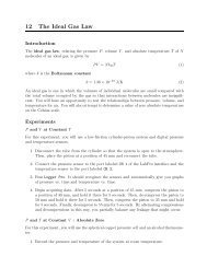
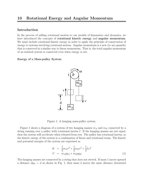
Figure 1: A hanging mass-pulley system.<br />
Figure 1 shows a diagram of a system of two hanging masses m A <strong>and</strong> m B connected by a<br />
string running over a pulley with rotational inertia I. If the hanging masses are not equal,<br />
then the system will accelerate when released from rest. The pulley has rotational inertia, so<br />
the kinetic energy of the system is a combination of linear <strong>and</strong> rotational terms. The kinetic<br />
<strong>and</strong> potential energies of the system are expressed as<br />
K = 1 2 m Av 2 + 1 2 m Bv 2 + 1 2 Iω2<br />
U = m A gy A +m B gy B (1)<br />
The hanging masses are connected by a string that does not stretch. If mass 1 moves upward<br />
a distance ∆y 1 = d as shown in Fig. 1, then mass 2 moves the same distance downward
∆y B = −d. A convenient coordinate system for describing changes in the vertical positions<br />
of the masses (for calculating potential energy, for example) is therefore<br />
y A = −y B (2)<br />
Furthermore, the string does not slip over the pulley, so the distance d is related to the<br />
angular position of the pulley in radians via<br />
<strong>and</strong> the angular <strong>and</strong> linear velocities are related via<br />
With Eq.’s 2-4, the energy expressions of Eq.’s 1 become<br />
d = Rθ (3)<br />
v = Rω (4)<br />
K = 1 (<br />
mA R 2 +m B R 2 +I ) ω 2<br />
2<br />
(5)<br />
U = (m A −m B )gRθ (6)<br />
If no work is done by forces other than gravity, <strong>and</strong> energy is conserved, then the total<br />
mechanical energy of the system E = K+U is constant. All of the quantities in Eq.’s 5 <strong>and</strong><br />
6 can be readily measured. You will have an opportunity to test conservation of energy for<br />
this system using a rotational motion detector <strong>and</strong> Logger Pro.<br />
A <strong>Rotational</strong> Collision<br />
Before<br />
After<br />
ω = 0 Β1<br />
ω Α1<br />
I B<br />
I A<br />
ω 2<br />
I A<br />
+<br />
I B<br />
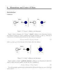
Figure 2: A perfectly inelastic rotational collision.<br />
Fig. 2 shows a perfectly inelastic (“sticky”) rotational collision in which an initially stationary<br />
object with rotational inertia I B is dropped onto another object with rotational<br />
inertia I A initially spinning with angular velocity ω A1 . After the collision, both objects spin<br />
together with angular velocity ω 2 .
The total angular momentum of an isolated system is conserved. The angular momentum<br />
of an object with rotational inertia I <strong>and</strong> angular velocity ω is given by<br />
L = Iω (7)<br />
Conservation of angular momentum for a two-body rotational collision is expressed<br />
L A1 +L B1 = L A2 +L B2 (8)<br />
For the perfectly inelastic rotational collision shown in Fig. 2, Eq. 8 becomes<br />
I A ω A1 = (I A +I B )ω 2 (9)<br />
You will test conservation of angular momentum for perfectly inelastic rotational collisions<br />
between the ring <strong>and</strong> disk you considered in <strong>Lab</strong> 9.<br />
Experiments<br />
Note : In order to analyze these measurements, you will need the rotational inertia of the<br />
aluminum disk <strong>and</strong> the heavy ring with uncertainties, which you measured as part of <strong>Lab</strong> 9.<br />
<strong>Energy</strong> of a Mass-pulley System<br />
1. Use the Vernier caliper to measure the diameter of the largest spool on the rotational<br />
motion sensor (RMS).<br />
2. Mount the RMS on the horizontal bar, away from the table so that the masses can<br />
hang freely from the pulley. The aluminum disk should be mounted on the RMS.<br />
3. Hang the two 50 g mass hangers over the largest spool of the RMS using the thread<br />
provided.<br />
4. Run Logger Pro <strong>and</strong> load the file <strong>Rotational</strong><strong>Energy</strong>.cmbl.<br />
5. Add a <strong>10</strong> g mass to one of the mass hangers, <strong>and</strong> measure the motion of the system as<br />
it accelerates. The system will slow down <strong>and</strong> stop on its own once the heavier mass<br />
hits the floor.<br />
6. Collectmeasurements offivecle<strong>and</strong>rops. (Rejectdropsduringwhichthemassescollide<br />
as they pass one another.)<br />
A <strong>Rotational</strong> Collision<br />
1. Mount the RMS on the vertical bar so that its rotational axis is aligned vertically.<br />
2. Measure the mass of the ring.<br />
3. Run Logger Pro <strong>and</strong> load the file <strong>Rotational</strong>Motion.cmbl.
4. Start acquiring RMS data with Logger Pro, <strong>and</strong> start the aluminum disk spinning at<br />
ω 1 ≈ 30 rad/s.<br />
5. Carefully hold the ring, smooth-side-down, centered over the disk. Gently drop the<br />
ring onto the disk from a height of no more than a few millimeters.<br />
CM of the Ring<br />
a<br />
h<br />
Axis of Rotation<br />
b<br />
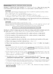
Figure 3: A typical collision in which the ring l<strong>and</strong>s a distance h off-center.<br />
6. It is very unlikely that the ring will be centered on the disk after the collision. Instead,<br />
it will usually end up with its center of mass some distance h from the axis of rotation<br />
of the system as shown in Fig. 3. You will need to correct the rotational inertia of<br />
the ring for this offset using the parallel axis theorem. The distance h is difficult to<br />
measure directly, but it isrelated tothe shortest <strong>and</strong>longest distances, a<strong>and</strong>bbetween<br />
the outside edges of the ring <strong>and</strong> disk by<br />
h = b−a<br />
2<br />
After you have your angular velocity data, <strong>and</strong> before you remove the ring from the<br />
disk, measure a <strong>and</strong> b as precisely as you can by using the metal rod that emerges from<br />
the end of the Vernier caliper.<br />
7. Collect data for at least five rotational collisions. Make sure that you have angular<br />
velocity data both before <strong>and</strong> after each collision.<br />
Analysis<br />
<strong>Energy</strong> of a Mass-pulley System<br />
Note : The aluminum disk provides rotational inertia, but does not act as the actual pulley,<br />
so in the analysis of your measurements, the radius R in Eq.’s 3-6 is the radius of the largest<br />
spool of the rotational motion detector, not the radius of the aluminum disk.<br />
1. Put your measured m A , m B , I, <strong>and</strong> R values into the calculation of the kinetic energy<br />
in Logger Pro. Click on Data -> Column Options -> Kinetic energy to bring up<br />
a Calculated Column Options widow. Choose the Column Definition tab. In the<br />
‘‘Equation’’ box, you should see<br />
(<strong>10</strong>)
1/2*((0.05+0.06)*0.02^2 + 0.0001)*"<strong>Angular</strong> Velocity"^2<br />
which follows the form of Eq. 5 with m A = 50 g, m B = 60 g, I = 0.0001 kgm 2 <strong>and</strong><br />
R = 2 cm. Replace the values of I <strong>and</strong> R with your measured values, <strong>and</strong> click Ok.<br />
2. Putyourmeasured m A , m B , I, <strong>and</strong>Rvaluesintothecalculationofthepotentialenergy<br />
in Logger Pro. Click on Data -> Column Options -> Potential energy to bring<br />
up a Calculated Column Options widow. Choose the Column Definition tab. In<br />
the ‘‘Equation’’ box, you should see<br />
(0.05-0.06)*9.8*0.02*abs("Angle")<br />
which follows the form of Eq. 6 with m A = 50 g, m B = 60 g, I = 0.0001 kgm 2 <strong>and</strong><br />
R = 2 cm. Replace the value of R with your measured value, <strong>and</strong> click Ok.<br />
3. Devise <strong>and</strong> carry out a strategy to determine whether or not your observations are<br />
compatible with the principle of conservation of mechanical energy within uncertainty.<br />
A <strong>Rotational</strong> Collision<br />
1. For each collision, devise <strong>and</strong> carry out a strategy for determining ω A1 <strong>and</strong> ω 2 from<br />
your measurements using Logger Pro.<br />
2. Use Excel to calculate L 1 <strong>and</strong> L 2 for all of your collision measurements. In calculating<br />
L 2 , we must use the parallel axis theorem to correct for the fact that the ring was<br />
off-center, so<br />
L 2 = (I A +I B +m ring h 2 )ω 2 (11)<br />
3. Don’tworryaboutevaluatingexperimentaluncertaintiesforthesemeasurements. These<br />
collisions are not repeatable, so it’s difficult to use a statistical approach here.<br />
Questions<br />
1. Discuss the compatiblility of your observations of the mass-pulley system with the<br />
principle of conservation of energy.<br />
2. Are your measurements of perfectly inelastic rotational collisions compatible with with<br />
the principle of conservation of angular momentum within <strong>10</strong>% In collisions where L<br />
was not conserved according to your analysis, what do you think may have happened