AT91SAM7A3-EK Evaluation Board User Guide - Atmel Corporation
AT91SAM7A3-EK Evaluation Board User Guide - Atmel Corporation
AT91SAM7A3-EK Evaluation Board User Guide - Atmel Corporation

You also want an ePaper? Increase the reach of your titles
YUMPU automatically turns print PDFs into web optimized ePapers that Google loves.
<strong>AT91SAM7A3</strong>-<strong>EK</strong> <strong>Evaluation</strong> <strong>Board</strong><br />
..............................................................................................<br />
<strong>User</strong> <strong>Guide</strong>
Table of Contents<br />
Section 1<br />
Overview............................................................................................... 1-1<br />
1.1 Scope........................................................................................................1-1<br />
1.2 Deliverables ..............................................................................................1-1<br />
1.3 The <strong>AT91SAM7A3</strong>-<strong>EK</strong> <strong>Evaluation</strong> <strong>Board</strong>..................................................1-1<br />
Section 2<br />
Setting Up the <strong>AT91SAM7A3</strong>-<strong>EK</strong> <strong>Evaluation</strong> <strong>Board</strong>............................. 2-1<br />
2.1 Electrostatic Warning ................................................................................2-1<br />
2.2 Requirements............................................................................................2-1<br />
2.3 Layout .......................................................................................................2-2<br />
2.4 Powering Up the <strong>Board</strong>.............................................................................2-3<br />
2.5 Backup Power Supply...............................................................................2-3<br />
2.6 Getting Started..........................................................................................2-3<br />
2.7 <strong>AT91SAM7A3</strong>-<strong>EK</strong> Block Diagram.............................................................2-4<br />
Section 3<br />
<strong>Board</strong> Description ................................................................................. 3-1<br />
3.1 <strong>AT91SAM7A3</strong> Microcontroller...................................................................3-1<br />
3.2 <strong>AT91SAM7A3</strong> Block Diagram...................................................................3-4<br />
3.3 Memory .....................................................................................................3-5<br />
3.4 Clock Circuitry...........................................................................................3-5<br />
3.5 Reset Circuitry ..........................................................................................3-5<br />
3.6 Shutdown Controller .................................................................................3-5<br />
3.7 Power Supply Circuitry..............................................................................3-5<br />
3.8 Remote Communication ...........................................................................3-5<br />
3.9 Analog Interface........................................................................................3-5<br />
3.10 <strong>User</strong> Interface ...........................................................................................3-5<br />
3.11 Debug Interface ........................................................................................3-6<br />
3.12 Expansion Slot ..........................................................................................3-6<br />
Section 4<br />
Configuration Straps ............................................................................. 4-1<br />
4.1 Configuration Straps .................................................................................4-1<br />
Section 5<br />
Schematics ........................................................................................... 5-1<br />
5.1 Schematics ...............................................................................................5-1<br />
Section 6<br />
Revision History.................................................................................... 6-1<br />
6.1 Revision History ........................................................................................6-1<br />
<strong>AT91SAM7A3</strong>-<strong>EK</strong> <strong>Evaluation</strong> <strong>Board</strong> <strong>User</strong> <strong>Guide</strong><br />
6165C–ATARM–26-Jun-06<br />
i
Section 1<br />
Overview<br />
1.1 Scope The <strong>AT91SAM7A3</strong>-<strong>EK</strong> evaluation kit enables evaluation capabilities and code development<br />
of applications running on an <strong>AT91SAM7A3</strong>.<br />
This guide focuses on the <strong>AT91SAM7A3</strong>-<strong>EK</strong> board as an evaluation platform.<br />
1.2 Deliverables The <strong>AT91SAM7A3</strong>-<strong>EK</strong> package contains the following items:<br />
! an <strong>AT91SAM7A3</strong>-<strong>EK</strong> board<br />
! one A/B-type USB cable<br />
! one serial RS232 cable<br />
! one DVD-ROM containing summary and full datasheets, datasheets with electrical<br />
and mechanical characteristics, application notes and getting started documents for<br />
all development boards and AT91 microcontrollers. An AT91 software package with C<br />
and assembly listings is also provided. This allows the user to begin evaluating the<br />
AT91 ARM ® Thumb ® 32-bit microcontroller quickly.<br />
1.3 The<br />
<strong>AT91SAM7A3</strong>-<strong>EK</strong><br />
<strong>Evaluation</strong> <strong>Board</strong><br />
The board is equipped with an <strong>AT91SAM7A3</strong> (100-pin LQFP Green package) together<br />
with the following:<br />
! USB device port interface<br />
! one DBGU serial communication port<br />
! JTAG/ICE debug interface connector<br />
! two serial CAN communication ports<br />
! one serial LIN communication port<br />
! one buffered analog input and PWM output<br />
! one Power LED and four general-purpose LEDs<br />
! one SD/MMC/DataFlash ® card slot<br />
! expansion connector<br />
! one <strong>Atmel</strong> ® serial DataFlash<br />
! one footprint for 3.6V lithium thionyl-chloride backup battery<br />
<strong>AT91SAM7A3</strong>-<strong>EK</strong> <strong>Evaluation</strong> <strong>Board</strong> <strong>User</strong> <strong>Guide</strong> 1-1<br />
6165C–ATARM–26-Jun-06
Overview<br />
1-2 <strong>AT91SAM7A3</strong>-<strong>EK</strong> <strong>Evaluation</strong> <strong>Board</strong> <strong>User</strong> <strong>Guide</strong><br />
6165C–ATARM–26-Jun-06
Section 2<br />
Setting Up the <strong>AT91SAM7A3</strong>-<strong>EK</strong><br />
<strong>Evaluation</strong> <strong>Board</strong><br />
2.1 Electrostatic<br />
Warning<br />
The <strong>AT91SAM7A3</strong>-<strong>EK</strong> evaluation board is shipped in a protective anti-static package.<br />
The board must not be subjected to high electrostatic potentials. A grounding strap or<br />
similar protective device should be worn when handling the board. Avoid touching the<br />
component pins or any other metallic element.<br />
2.2 Requirements In order to set up the <strong>AT91SAM7A3</strong>-<strong>EK</strong> evaluation board, the following items are<br />
required:<br />
! the <strong>AT91SAM7A3</strong>-<strong>EK</strong> evaluation board itself<br />
! an A/B-type USB cable<br />
or<br />
! a DC USB power adapter (5V at 0.5 A) with USB A/B cable<br />
Note:<br />
The <strong>AT91SAM7A3</strong>-<strong>EK</strong> is not delivered with a JTAG/ICE interface which is<br />
required to start evaluating the device.<br />
<strong>AT91SAM7A3</strong>-<strong>EK</strong> <strong>Evaluation</strong> <strong>Board</strong> <strong>User</strong> <strong>Guide</strong> 2-1<br />
6165C–ATARM–26-Jun-06
Setting Up the <strong>AT91SAM7A3</strong>-<strong>EK</strong> <strong>Evaluation</strong> <strong>Board</strong><br />
2.3 Layout<br />
Figure 2-1. Top Level Layout<br />
2-2 <strong>AT91SAM7A3</strong>-<strong>EK</strong> <strong>Evaluation</strong> <strong>Board</strong> <strong>User</strong> <strong>Guide</strong><br />
6165C–ATARM–26-Jun-06
Setting Up the <strong>AT91SAM7A3</strong>-<strong>EK</strong> <strong>Evaluation</strong> <strong>Board</strong><br />
2.4 Powering Up the<br />
<strong>Board</strong><br />
<strong>AT91SAM7A3</strong> is self-powered by the USB port or by a USB power adapter.<br />
2.5 Backup Power<br />
Supply<br />
The user may add a battery (SAFT LS14250 3.6V or equivalent) in order to permanently<br />
power the backup part of the device. In this case, the configuration of J16, S6 and S7<br />
must be changed.<br />
Refer to Table 4-1.<br />
2.6 Getting Started The <strong>AT91SAM7A3</strong>-<strong>EK</strong> evaluation board is delivered with a DVD-ROM containing all<br />
necessary information and step-by-step procedures for working with the most common<br />
development tool chains. Please refer to this DVD-ROM, or to the <strong>Atmel</strong> web site,<br />
http://www.atmel.com/products/AT91/, for the most up-to-date information on getting<br />
started with the <strong>AT91SAM7A3</strong>-<strong>EK</strong>.<br />
Note that the <strong>AT91SAM7A3</strong> microcontroller fitted on the evaluation board has been programmed<br />
with the SAM Boot Assistant (SAM-BA ) which provides an easy way to<br />
program the embedded Flash memory through the USB or DBGU communication<br />
channel.<br />
Programming through DBGU requires that the evaluation kit is powered using a Power<br />
Supply USB Adapter<br />
Note: The SAM-BA Boot Assistant resides in the embedded Flash memory and will be<br />
deleted when programming the Flash. A JTAG/ICE interface is required to recover<br />
SAM-BA Boot Assistant.<br />
<strong>AT91SAM7A3</strong>-<strong>EK</strong> <strong>Evaluation</strong> <strong>Board</strong> <strong>User</strong> <strong>Guide</strong> 2-3<br />
6165C–ATARM–26-Jun-06
Setting Up the <strong>AT91SAM7A3</strong>-<strong>EK</strong> <strong>Evaluation</strong> <strong>Board</strong><br />
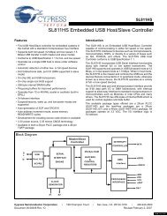
2.7 <strong>AT91SAM7A3</strong>-<strong>EK</strong><br />
Block Diagram<br />
Figure 2-2. Block Diagram<br />
J5 J4 J3<br />
VBUS<br />
CANL<br />
CANH<br />
1<br />
CANL<br />
CANH<br />
1<br />
LIN<br />
1<br />
DBGU<br />
RS232<br />
J2<br />
USB DEVICE<br />
J1<br />
VBUS<br />
SD/MMC<br />
DATAFLASH (NPCS03)<br />
CARD READER<br />
J7<br />
J9<br />
TXD<br />
RXD<br />
IN<br />
3.3V<br />
OUT<br />
3V3<br />
3V3<br />
5V<br />
3V3<br />
5V<br />
ATA6661<br />
MN18<br />
ADM3202A<br />
8 7 6 5 4 3 2 1 9<br />
S6<br />
nSHUTDOWN<br />
TJA1050<br />
RS<br />
TJA1050<br />
RS<br />
S7<br />
PIO<br />
YELLOW<br />
18.432 MHz<br />
VDDPLL<br />
EXT CLK INPUT<br />
POWER LED<br />
LIGHTED WHEN POWER ON<br />
J14<br />
J26<br />
VDD1V8<br />
XOUT<br />
XIN<br />
SHDN<br />
VDD3V3<br />
NRST<br />
SYSTEM CONTROLLER<br />
VDDBU<br />
J13<br />
FORCE WAKE-UP<br />
WAKE-UP1<br />
BP2<br />
NRST<br />
MANUAL RESET<br />
JTAG/ICE<br />
CAN0<br />
PIO<br />
VDDANA<br />
ADVREFP<br />
GNDANA<br />
ADC<br />
CAN1<br />
ADC0_AD3<br />
ADC0_AD2<br />
USART0<br />
DRXD - DTXD<br />
DBGU<br />
1K5<br />
PIO<br />
PWM0..PWM7<br />
DDP<br />
DDM<br />
USB<br />
<strong>AT91SAM7A3</strong>-LQFP100<br />
ATMEL<br />
SERIAL<br />
DATAFLASH<br />
CS<br />
SPI0<br />
PIO B<br />
MCI<br />
PIO A PIO B<br />
PIO A - PIO B EXPANSION CONNECTOR<br />
3V3<br />
R18 470R<br />
VDD BACKUP SELECT<br />
R20<br />
470R<br />
3<br />
1<br />
2<br />
J16<br />
3.3VANA<br />
3<br />
2<br />
1<br />
J17<br />
GNDANA<br />
PWM0<br />
PWM2<br />
PWM3<br />
PWM6<br />
PWM7<br />
3.6V 3V6 BP3<br />
NOT POPULATED<br />
BP4<br />
3.00V +- 0.2%<br />
EXTERNAL REF<br />
0 TO VREF<br />
EXTERNAL INPUT<br />
0 TO VREF<br />
PWM VOLTAGE GEN.<br />
DS1<br />
DS2<br />
DS3<br />
DS4<br />
1<br />
4<br />
2<br />
5<br />
3 6<br />
BP1<br />
J8<br />
JTAG/ICE CONNECTOR<br />
USER'S GREEN LED<br />
USER'S TACT SWITCH<br />
1<br />
J6<br />
ANALOG INPUT<br />
2-4 <strong>AT91SAM7A3</strong>-<strong>EK</strong> <strong>Evaluation</strong> <strong>Board</strong> <strong>User</strong> <strong>Guide</strong><br />
6165C–ATARM–26-Jun-06
Section 3<br />
<strong>Board</strong> Description<br />
3.1 <strong>AT91SAM7A3</strong><br />
Microcontroller<br />
! Incorporates the ARM7TDMI ® ARM ® Thumb ® Processor<br />
– High-performance 32-bit RISC Architecture<br />
– High-density 16-bit Instruction Set<br />
– Leader in MIPS/Watt<br />
! Embedded ICE In-circuit Emulation, Debug Communication Channel Support<br />
! 256 Kbytes of Internal High-speed Flash, Organized in 1024 Pages of 256 Bytes<br />
– Single Cycle Access at Up to 30 MHz in Worst Case Conditions<br />
– Prefetch Buffer Optimizing Thumb Instruction Execution at Maximum Speed<br />
– Page Programming Time: 6 ms, Including Page Auto-erase, Full Erase Time:<br />
15 ms<br />
– 10,000 Write Cycles, 10-year Data Retention Capability, Sector Lock<br />
Capabilities<br />
! 32K Bytes of Internal High-speed SRAM, Single-cycle Access at Maximum Speed<br />
! Memory Controller (MC)<br />
– Embedded Flash Controller, Abort Status and Misalignment Detection<br />
– Memory Protection Unit<br />
! Reset Controller (RSTC)<br />
– Based on Three Power-on Reset Cells<br />
– Provides External Reset Signal Shaping and Reset Sources Status<br />
! Clock Generator (CKGR)<br />
– Low-power RC Oscillator, 3 to 20 MHz On-chip Oscillator and One PLL<br />
! Power Management Controller (PMC)<br />
– Power Optimization Capabilities, including Slow Clock Mode (Down to 500<br />
Hz), Idle Mode, Standby Mode and Backup Mode<br />
– Four Programmable External Clock Signals<br />
! Advanced Interrupt Controller (AIC)<br />
– Individually Maskable, Eight-level Priority, Vectored Interrupt Sources<br />
<strong>AT91SAM7A3</strong>-<strong>EK</strong> <strong>Evaluation</strong> <strong>Board</strong> <strong>User</strong> <strong>Guide</strong> 3-1<br />
6165C–ATARM–26-Jun-06
<strong>Board</strong> Description<br />
– Four External Interrupt Sources and One Fast Interrupt Source, Spurious<br />
Interrupt Protected<br />
! Debug Unit (DBGU)<br />
– 2-wire UART and Support for Debug Communication Channel interrupt<br />
! Periodic Interval Timer (PIT)<br />
– 20-bit Programmable Counter plus 12-bit Interval Counter<br />
! Windowed Watchdog (WDT)<br />
– 12-bit key-protected Programmable Counter<br />
– Provides Reset or Interrupt Signal to the System<br />
– Counter May Be Stopped While the Processor is in Debug Mode or in Idle<br />
State<br />
! Real-time Timer (RTT)<br />
– 32-bit Free-running Counter with Alarm<br />
– Runs Off the Internal RC Oscillator<br />
! Two Parallel Input/Output Controllers (PIO)<br />
– Sixty-two Programmable I/O Lines Multiplexed with up to Two Peripheral I/Os<br />
– Input Change Interrupt Capability on Each I/O Line<br />
– Individually Programmable Open-drain, Pull-up resistor and Synchronous<br />
Output<br />
! Shutdown Controller (SHDWC)<br />
– Programmable Shutdown Pin and Wake-up Circuitry<br />
! Two 32-bit Battery Backup Registers for a Total of 8 Bytes<br />
! One 8-channel 20-bit PWM Controller (PMWC)<br />
! One USB 2.0 Full Speed (12 Mbits per Second) Device Port<br />
– On-chip Transceiver, 2-Kbyte Configurable Integrated FIFOs<br />
! Nineteen Peripheral Data Controller (PDC) Channels<br />
! Two CAN 2.0B Active Controllers, Supporting 11-bit Standard and 29-bit Extended<br />
Identifiers<br />
– 16 Fully Programmable Message Object Mailboxes, 16-bit Time Stamp<br />
Counter<br />
! Two 8-channel 10-bit Analog-to-Digital Converter<br />
! Three Universal Synchronous/Asynchronous Receiver Transmitters (USART)<br />
– Individual Baud Rate Generator, IrDA ® Infrared Modulation/Demodulation<br />
– Support for ISO7816 T0/T1 Smart Card, Hardware Handshaking, RS485<br />
Support<br />
! Two Master/Slave Serial Peripheral Interfaces (SPI)<br />
– 8- to 16-bit Programmable Data Length, Four External Peripheral Chip Selects<br />
! Three 3-channel 16-bit Timer/Counters (TC)<br />
– Three External Clock Inputs, Two Multi-purpose I/O Pins per Channel<br />
– Double PWM Generation, Capture/Waveform Mode, Up/Down Capability<br />
3-2 <strong>AT91SAM7A3</strong>-<strong>EK</strong> <strong>Evaluation</strong> <strong>Board</strong> <strong>User</strong> <strong>Guide</strong><br />
6165C–ATARM–26-Jun-06
<strong>Board</strong> Description<br />
! Two Synchronous Serial Controllers (SSC)<br />
– Independent Clock and Frame Sync Signals for Each Receiver and<br />
Transmitter<br />
– I²S Analog Interface Support, Time Division Multiplex Support<br />
– High-speed Continuous Data Stream Capabilities with 32-bit Data Transfer<br />
! One Two-wire Interface (TWI)<br />
– Master Mode Support Only, All Two-wire <strong>Atmel</strong> EEPROMs Supported<br />
! Multimedia Card Interface (MCI)<br />
– Compliant with Multimedia Cards and SD Cards<br />
– Automatic Protocol Control and Fast Automatic Data Transfers with PDC,<br />
MMC and SDCard Compliant<br />
! IEEE ® 1149.1 JTAG Boundary Scan on All Digital Pins<br />
! Required Power Supplies<br />
– Embedded 1.8V Regulator, Drawing up to 130 mA for the Core and the<br />
External Components, Enables 3.3V Single Supply Mode<br />
– 3.3V VDD3V3 Regulator, I/O Lines and Flash Power Supply<br />
– 1.8V VDD1V8 Output of the Voltage Regulator and Core Power Supply<br />
– 3V to 3.6V VDDANA ADC Power Supply<br />
– 3V to 3.6V VDDBU Backup Power Supply<br />
! 5V-tolerant I/Os<br />
! Fully Static Operation: 0 Hz to 60 MHz at 1.65V and 85°C Worst Case Conditions<br />
! Available in a 100-lead LQFP Green Package<br />
<strong>AT91SAM7A3</strong>-<strong>EK</strong> <strong>Evaluation</strong> <strong>Board</strong> <strong>User</strong> <strong>Guide</strong> 3-3<br />
6165C–ATARM–26-Jun-06
<strong>Board</strong> Description<br />
3-4 <strong>AT91SAM7A3</strong>-<strong>EK</strong> <strong>Evaluation</strong> <strong>Board</strong> <strong>User</strong> <strong>Guide</strong><br />
6165C–ATARM–26-Jun-06<br />
3.2 <strong>AT91SAM7A3</strong><br />
Block Diagram<br />
Figure 3-1. Block Diagram<br />
TF0<br />
TK0<br />
TD0<br />
RD0<br />
RK0<br />
RF0<br />
TCLK0<br />
TCLK1<br />
TCLK2<br />
TIOA0<br />
TIOB0<br />
TIOA1<br />
TIOB1<br />
TIOA2<br />
TIOB2<br />
CANRX0<br />
CANTX0<br />
CANRX1<br />
CANTX1<br />
TF1<br />
TK1<br />
TD1<br />
RD1<br />
RK1<br />
RF1<br />
TCLK3<br />
TCLK4<br />
TCLK5<br />
TIOA3<br />
TIOB3<br />
TIOA4<br />
TIOB4<br />
TIOA5<br />
TIOB5<br />
TCLK6<br />
TCLK7<br />
TCLK8<br />
TIOA6<br />
TIOB6<br />
TIOA7<br />
TIOB7<br />
TIOA8<br />
TIOB8<br />
TWD<br />
TWCK<br />
PWM0<br />
PWM1<br />
PWM2<br />
PWM3<br />
PWM4<br />
PWM5<br />
PWM6<br />
PWM7<br />
DDM<br />
DDP<br />
TDI<br />
TDO<br />
TMS<br />
TCK<br />
Peripheral Bridge<br />
Peripheral Data<br />
Controller<br />
SRAM<br />
32K Bytes<br />
ARM7TDMI<br />
Processor<br />
ICE<br />
JTAG<br />
SCAN<br />
JTAGSEL<br />
USART0<br />
SSC0<br />
Timer Counter<br />
RXD0<br />
TXD0<br />
SCK0<br />
RTS0<br />
CTS0<br />
SPI0_NPCS0<br />
SPI0_NPCS1<br />
SPI0_NPCS2<br />
SPI0_NPCS3<br />
SPI0_MISO<br />
SPI0_MOSI<br />
SPI0_SPCK<br />
FLASH<br />
256K Bytes<br />
Memory<br />
Controller<br />
Memory<br />
Protection<br />
Unit<br />
Abort<br />
Status<br />
Address<br />
Decoder<br />
Misalignment<br />
Detection<br />
PIO<br />
PIO<br />
APB<br />
Embedded<br />
Flash<br />
Controller<br />
ADC0_AD0<br />
ADC0_AD1<br />
ADC0_AD2<br />
ADC0_AD3<br />
ADC0_AD4<br />
ADC0_AD5<br />
ADC0_AD6<br />
ADC0_AD7<br />
CAN0<br />
ADC0_ADTRG<br />
19 channels<br />
PDC<br />
PDC<br />
USART1<br />
RXD1<br />
TXD1<br />
SCK1<br />
RTS1<br />
CTS1<br />
PDC<br />
PDC<br />
PDC<br />
PDC<br />
SPI0<br />
SPI1_NPCS0<br />
SPI1_NPCS1<br />
SPI1_NPCS2<br />
SPI1_NPCS3<br />
SPI1_MISO<br />
SPI1_MOSI<br />
SPI1_SPCK<br />
PDC<br />
PDC<br />
SPI1<br />
PDC<br />
ADC0<br />
GND<br />
VDDANA<br />
ADVREFP<br />
CAN1<br />
PDC<br />
PDC<br />
SSC1<br />
PDC<br />
PDC<br />
TC0<br />
TC1<br />
TC2<br />
Timer Counter<br />
TC3<br />
TC4<br />
TC5<br />
Timer Counter<br />
TC6<br />
TC7<br />
TC8<br />
TWI<br />
VDD3V3<br />
GND<br />
VDD1V8<br />
RXD2<br />
TXD2<br />
SCK2<br />
RTS2<br />
CTS2<br />
USART2<br />
PDC<br />
PDC<br />
ADC1<br />
PDC<br />
ADC1_ADTRG<br />
ADC1_AD0<br />
ADC1_AD1<br />
ADC1_AD2<br />
ADC1_AD3<br />
ADC1_AD4<br />
ADC1_AD5<br />
ADC1_AD6<br />
ADC1_AD7<br />
PWMC<br />
1.8 V<br />
Voltage<br />
Regulator<br />
MCCK<br />
MCCDA<br />
MCDA0-MCDA3<br />
MCI<br />
PDC<br />
USB Device<br />
FIFO<br />
Transceiver<br />
NRST<br />
FIQ<br />
IRQ0-IRQ3<br />
PCK0-PCK3<br />
PMC<br />
AIC<br />
PLL<br />
RCOSC<br />
PIOB<br />
Reset<br />
Controller<br />
DRXD<br />
DTXD<br />
POR<br />
PLLRC<br />
OSC<br />
XIN<br />
XOUT<br />
POR<br />
VDDBU<br />
TST<br />
DBGU<br />
PDC<br />
PDC<br />
PIO<br />
PIT<br />
WDT<br />
RTT<br />
System Controller<br />
VDD3V3<br />
PIOA<br />
VDD1V8 POR<br />
Shutdown<br />
Controller<br />
FWKUP<br />
WKUP0<br />
WKUP1<br />
SHDW<br />
GND<br />
VDDBU<br />
GPBR<br />
PDC
<strong>Board</strong> Description<br />
3.3 Memory ! 256 Kbytes of Internal High-speed Flash<br />
! 32 Kbytes of Internal High-speed SRAM<br />
! <strong>Atmel</strong> serial DataFlash<br />
3.4 Clock Circuitry ! 18.432 MHz standard crystal for the embedded oscillator<br />
! 32 KHz internal RC oscillator<br />
3.5 Reset Circuitry ! Internal reset controller with a bi-directional reset pin<br />
! External reset pushbutton<br />
3.6 Shutdown<br />
Controller<br />
! Programmable shutdown and Wake-Up<br />
! Force Wake-Up and Wake-up pushbutton<br />
3.7 Power Supply<br />
Circuitry<br />
! USB powered, the dynamic power consumption on VDD1V8 is less than 50 mA at full<br />
speed when running out of the Flash. The total current at power-up is less than 100<br />
mA.<br />
! External power can be applied via USB Power adapter 5V 0.5A with USB A/B cable<br />
! On-chip embedded VDDCORE 1.8V regulator<br />
! On-board 3.3V linear regulator with shutdown control<br />
3.8 Remote<br />
Communication<br />
! One Serial interface (DBGU COM Port) via RS-232 DB9 male socket<br />
! USB V2.0 Full-speed compliant, 12 Mbits per second (UDP)<br />
! Two CAN 2.0B communication ports via the 3-position printed circuit terminal block<br />
! One LIN communication port via the 3-position printed circuit terminal block<br />
3.9 Analog Interface ! One selectable 0.2% 3.00V Vref or 3.3V ANA<br />
! One 3-position printed circuit terminal block<br />
! Two analog up to Vref inputs. One external user input and one back-looped with<br />
buffered PWM0 output.<br />
! One buffered PWM0 analog output (up to Vref)<br />
3.10 <strong>User</strong> Interface ! One 5-way joystick (4 directions and push for confirmation)<br />
! Four general-purpose buffered green LEDs (PWM controlled)<br />
<strong>AT91SAM7A3</strong>-<strong>EK</strong> <strong>Evaluation</strong> <strong>Board</strong> <strong>User</strong> <strong>Guide</strong> 3-5<br />
6165C–ATARM–26-Jun-06
<strong>Board</strong> Description<br />
! One yellow power LED (can also be software controlled)<br />
3.11 Debug Interface ! 20-pin JTAG/ICE interface connector<br />
! DBGU serial RS232 COM Port<br />
3.12 Expansion Slot ! One SD/MMC/DataFlash card slot<br />
! All I/Os of the <strong>AT91SAM7A3</strong> are routed to peripheral extension connectors (J9). This<br />
allows the developer to check the integrity of the components and to extend the<br />
features of the board by adding external hardware components or boards.<br />
3-6 <strong>AT91SAM7A3</strong>-<strong>EK</strong> <strong>Evaluation</strong> <strong>Board</strong> <strong>User</strong> <strong>Guide</strong><br />
6165C–ATARM–26-Jun-06
Section 4<br />
Configuration Straps<br />
4.1 Configuration<br />
Straps<br />
Table 4-1. Configuration Jumpers and Straps<br />
Default<br />
Designation Setting<br />
J13 Closed VDD3V3 Jumper (1)<br />
J14 Closed VDDPLL Jumper (1)<br />
J15 Closed VDDANA Jumper (1)<br />
Feature<br />
J16 2-3 VDDBU Jumper select (1)<br />
1-2 : Optional Lithium Thionyl Chloride 3.6V Backup<br />
Battery<br />
2-3 : 3.3V power<br />
J17 1-2 ADVREFP Jumper select (1)<br />
1-2 : 3.00V Voltage reference<br />
2-3 : VDDANA<br />
J18 Closed Enables 120 ohms CAN bus resistance termination<br />
(CAN0)<br />
J19 Closed Enables 5V power supply for TJA1050 Transceiver. It is<br />
closed by wire on solder side. J19 and J20 should not be<br />
closed at the same time.<br />
J20 Open Disables 3.3V power supply for TJA1050 Transceiver. J20<br />
and J19 should not be closed at the same time.<br />
J21 Closed Enables 120 ohms CAN bus resistance termination<br />
(CAN1)<br />
J22 Closed Enables 5V power supply for TJA1050 Transceiver. It is<br />
closed by wire on solder side. J22 and J23 should not be<br />
closed at the same time.<br />
J23 Opened Disables 3.3V power supply for TJA1050 Transceiver. J23<br />
and J22 should not be closed at the same time.<br />
J24 Opened Do not use: Factory test mode<br />
J25 Opened Select ICE mode or JTAG mode (Closed)<br />
J26 Opened External XIN clock input. S8 and S9 must be open.<br />
<strong>AT91SAM7A3</strong>-<strong>EK</strong> <strong>Evaluation</strong> <strong>Board</strong> <strong>User</strong> <strong>Guide</strong> 4-1<br />
6165C–ATARM–26-Jun-06
Configuration Straps<br />
Table 4-1. Configuration Jumpers and Straps (Continued)<br />
Designation<br />
S1 Opened Solder it, enables permanent pull up on USB DP. S3 must<br />
be open.<br />
S2 Closed The System Reset signal (NRST) is connected to the<br />
ICE/JTAG socket (J8, pin 15).<br />
S3 Closed Enables the use of the USB DP PUP (PB1)<br />
S4 Closed Enables the use of the USB CNX detection (PB0)<br />
S5 Closed Digital Analog GND planes separation. Do not cut it<br />
S6<br />
S7<br />
Default<br />
Setting<br />
Closed<br />
Opened<br />
Opened<br />
Closed<br />
Disables shutdown control and forces Power on.<br />
Do not close at same time as S7.<br />
Enables shutdown control<br />
Disables shut down control<br />
Enables shutdown control<br />
Do not close at same time as S6.<br />
S8 - S9 Closed Enables the use of 18.432 MHz crystal. Must be open if<br />
external clock used.<br />
S10 Closed Enables the Power LED control<br />
S11 Closed Enables the use of the NPCS13<br />
S12 Opened Disable Serial DataFlash write protect<br />
S13 Closed Enables the use of the TXD CAN0 transceiver (PA27)<br />
S14 Closed Enables the use of the RXD CAN0 transceiver (PA26)<br />
S15 Closed Enables control of the Standby/Normal mode for CAN0<br />
and CAN1 transceivers (PA23)<br />
S16 Closed Enables the use of the TXD CAN1 transceiver (PA29)<br />
S17 Closed Enables the use of the RXD CAN1 transceiver (PA28)<br />
S18 Opened Enables control of the Standby/Normal mode for CAN0<br />
and CAN1 transceivers (PA23).<br />
If S18 is closed, S15 must be open.<br />
S19 Closed Enables the use of PWM0 Analog Output (PA18)<br />
S20 Closed Enables the use of AD02 Analog Input (PB16)<br />
S21 Closed Enables the use of AD03 Analog Input (PB17)<br />
S22 Closed Enables the use of the TXD LIN transceiver (PA3)<br />
S23 Closed Enables the use of the RXD LIN transceiver (PA2)<br />
S24 Closed Enables the control of the EN LIN transceiver (PA5)<br />
S25 Closed Enables the control of the INH LIN transceiver (PA6)<br />
S26 Opened Do not use<br />
Feature<br />
S27 Closed Enables the use of the <strong>User</strong> LED DS4 (PA25)<br />
S28 Closed Enables the use of the <strong>User</strong> LED DS3 (PA24)<br />
S29 Closed Enables the use of the <strong>User</strong> LED DS2 (PA21)<br />
S30 Closed Enables the use of the <strong>User</strong> LED DS1 (PA20)<br />
4-2 <strong>AT91SAM7A3</strong>-<strong>EK</strong> <strong>Evaluation</strong> <strong>Board</strong> <strong>User</strong> <strong>Guide</strong><br />
6165C–ATARM–26-Jun-06
Configuration Straps<br />
Table 4-1. Configuration Jumpers and Straps (Continued)<br />
Designation<br />
Default<br />
Setting<br />
S31 Closed Enables the use of the DBGU TXD signal (PA31)<br />
S32 Closed Enables the use of the DBGU RXD signal (PA30)<br />
S33 Opened Disable VUSB power supply on J9 extension connector.<br />
TP1 N.A GND Test point<br />
TP2 N.A GND Test point<br />
TP3 N.A GND_ADC Test point<br />
Feature<br />
Note: 1. These jumpers are provided for measuring power consumption. By default, they are<br />
closed. To use this feature, the user has to open the strap and insert an anmeter.<br />
<strong>AT91SAM7A3</strong>-<strong>EK</strong> <strong>Evaluation</strong> <strong>Board</strong> <strong>User</strong> <strong>Guide</strong> 4-3<br />
6165C–ATARM–26-Jun-06
Configuration Straps<br />
4-4 <strong>AT91SAM7A3</strong>-<strong>EK</strong> <strong>Evaluation</strong> <strong>Board</strong> <strong>User</strong> <strong>Guide</strong><br />
6165C–ATARM–26-Jun-06
Section 5<br />
Schematics<br />
5.1 Schematics This section contains the following schematics:<br />
! Processor<br />
! I/O<br />
<strong>AT91SAM7A3</strong>-<strong>EK</strong> <strong>Evaluation</strong> <strong>Board</strong> <strong>User</strong> <strong>Guide</strong> 5-1<br />
6165C–ATARM–26-Jun-06
D<br />
C<br />
B<br />
A<br />
8<br />
USB DEVICE INTERFACE<br />
IN<br />
1<br />
OUT<br />
2<br />
G 6<br />
GND<br />
3<br />
NR<br />
4<br />
EN<br />
5<br />
3V3<br />
S1<br />
7<br />
MN2<br />
USBUF02W6<br />
3V3<br />
6<br />
5<br />
DDP 98<br />
DDM 97<br />
NRST<br />
TST<br />
PA0/TWD/ADC0_ADTRG<br />
PA1/TWCK/ADC1_ADTRG<br />
PA2/RXD0<br />
PA3/TXD0<br />
PA4/SCK0/SPI1_NPCS0<br />
PA5/RTS0/SPI1_NPCS1<br />
PA6/CTS0/SPI1_NPCS2<br />
PA7/RXD1/SPI1_NPCS3<br />
PA8/TXD1/SPI1_MISO<br />
PA9/RXD2/SPI1_MOSI<br />
PA10/TXD2/SPI1_SPCK<br />
PA11/SPI0_NPCS0<br />
PA12/SPI0_NPCS1/MCDA1<br />
PA13/SPI0_NPCS2/MCDA2<br />
PA14/SPI0_NPCS3/MCDA3<br />
PA15/SPI0_MISO/MCDA0<br />
PA16/SPI0_MOSI/MCCDA<br />
PA17/SPI0_SPCK/MCCK<br />
PA18/PWM0/PCK0<br />
PA19/PWM1/PCK1<br />
PA20/PWM2/PCK2<br />
PA21/PWM3/PCK3<br />
PA22/PWM4/IRQ0<br />
PA23/PWM5/IRQ1<br />
PA24/PWM6/TCLK4<br />
PA25/PWM7/TCLK5<br />
PA26/CANRX0<br />
PA27/CANTX0<br />
PA28/CANRX1/TCLK3<br />
PA29/CANTX1/TCLK6<br />
PA30/DRXD/TCLK7<br />
PA31/DTXD/TCLK8<br />
21<br />
22<br />
23<br />
24<br />
32<br />
33<br />
34<br />
35<br />
36<br />
37<br />
41<br />
42<br />
43<br />
44<br />
45<br />
46<br />
47<br />
48<br />
49<br />
50<br />
51<br />
52<br />
53<br />
54<br />
55<br />
56<br />
57<br />
58<br />
62<br />
63<br />
64<br />
65<br />
PA0<br />
PA1<br />
PA2<br />
PA3<br />
PA4<br />
PA5<br />
PA6<br />
PA7<br />
PA8<br />
PA9<br />
PA10<br />
PA11<br />
PA12<br />
PA13<br />
PA14<br />
PA15<br />
PA16<br />
PA17<br />
PA18<br />
PA19<br />
PA20<br />
PA21<br />
PA22<br />
PA23<br />
PA24<br />
PA25<br />
PA26<br />
PA27<br />
PA28<br />
PA29<br />
PA30<br />
PA31<br />
2<br />
3<br />
4<br />
JTAGSEL<br />
66<br />
TDO 70<br />
TCK 69<br />
TMS 68<br />
TDI<br />
67<br />
MANUAL RESET<br />
3<br />
3<br />
2<br />
1<br />
JTAG INTERFACE<br />
J1<br />
BP2<br />
RR1<br />
USB B<br />
6 1<br />
100K<br />
J8<br />
1<br />
2<br />
3V3<br />
3V3<br />
1 2<br />
5<br />
3V3<br />
2<br />
3 4<br />
4<br />
3<br />
5 6<br />
J24<br />
J25<br />
7 8<br />
4<br />
3<br />
9 10<br />
6 5<br />
3V3<br />
DNP DNP<br />
11 12<br />
13 14<br />
15 16<br />
17 18<br />
R1<br />
S2 19 20<br />
3 2<br />
3V3<br />
10K<br />
NRST<br />
3V3<br />
Q5<br />
R2<br />
3V3_ADC<br />
J15<br />
L1<br />
4.7µH<br />
Si2301BDS<br />
100K<br />
S3<br />
USB_DP_PUP<br />
PB1<br />
C1<br />
10 uF 10V<br />
Q1<br />
5V<br />
Si2301BDS<br />
TP3<br />
VUSB<br />
S5<br />
2<br />
3<br />
ANALOG GND<br />
MN1<br />
GND_ADC<br />
J17<br />
VDD1V8<br />
C4 10 uF 99<br />
MN4<br />
VDD1V8<br />
3.00V +- 0.2%<br />
MN3<br />
R4<br />
C7<br />
100NF<br />
17<br />
VDD1V8<br />
VDDANA 77<br />
5<br />
TPS73633<br />
C8<br />
100NF<br />
REF<br />
1<br />
100K<br />
VOUT<br />
40<br />
VDD1V8<br />
C5<br />
C3<br />
C10<br />
100NF<br />
59<br />
3V3_ADC<br />
VDD1V8<br />
100NF<br />
C6<br />
GND_ADC<br />
S6<br />
100NF<br />
22NF<br />
GND 2<br />
3<br />
3V3 CURRENT<br />
J13<br />
3V3<br />
MEASURE<br />
C11<br />
4<br />
VIN EN 3<br />
100<br />
Q2<br />
C2<br />
10 uF<br />
VDD3V3<br />
ADVREFP 78<br />
22NF<br />
15<br />
C9<br />
Si2302BDS<br />
C12<br />
100NF<br />
VDD3V3<br />
38<br />
GND_ADC<br />
10 uF<br />
LM4120AIM5-3.0<br />
VDD3V3<br />
GND_ADC<br />
1<br />
C13<br />
100NF<br />
61<br />
10V<br />
VREF<br />
C14<br />
100NF<br />
VDD3V3<br />
88<br />
3V3<br />
C18<br />
100NF<br />
VDD3V3<br />
PB29<br />
ADC1_AD7/SCK2/TIOB8/PB29<br />
96<br />
2 PB28<br />
ADC1_AD6/CTS2/TIOA8/PB28<br />
95<br />
S33<br />
S7<br />
1<br />
PB27<br />
VUSB<br />
GND<br />
ADC1_AD5/RTS2/TIOB7/PB27<br />
94<br />
16<br />
PB26<br />
GND<br />
ADC1_AD4/SCK1/TIOA7/PB26<br />
93<br />
25<br />
PB25<br />
GND<br />
ADC1_AD3/CTS1/TIOB6/PB25<br />
92<br />
31<br />
PB24<br />
TWD PA0<br />
PB0<br />
GND<br />
ADC1_AD2/RTS1/TIOA6/PB24<br />
91<br />
A1<br />
B1<br />
C1<br />
39<br />
PB23<br />
TWCK PA1<br />
PB1<br />
GND<br />
ADC1_AD1/TIOB5/PB23<br />
90<br />
A2<br />
B2<br />
C2<br />
60<br />
PB22<br />
RXD0 PA2<br />
TF0 PB2<br />
RXD0<br />
GND<br />
ADC1_AD0/TIOA5/PB22<br />
89<br />
A3<br />
B3<br />
C3<br />
C15<br />
C16<br />
C17<br />
71<br />
PB21<br />
TXD0 PA3<br />
TK0 PB3<br />
TXD0<br />
GND<br />
<strong>AT91SAM7A3</strong> ADC0_AD7/NPCS13/TIOB4/PB21<br />
87<br />
A4<br />
B4<br />
C4<br />
1µF<br />
1µF<br />
10NF<br />
75<br />
PB20<br />
SCK0 PA4<br />
TD0 PB4<br />
SCK0<br />
GND<br />
ADC0_AD6/NPCS12/TIOA4/PB20<br />
86<br />
A5<br />
B5<br />
C5<br />
USART<br />
79<br />
PB19<br />
RTS0 PA5<br />
RD0 PB5<br />
RTS0<br />
TP1<br />
GND<br />
ADC0_AD5/NPCS11/TIOB3/PB19<br />
85<br />
A6<br />
B6<br />
C6<br />
PB18<br />
CTS0 PA6<br />
RK0 PB6<br />
CTS0<br />
S8<br />
ADC0_AD4/PWM4/TIOA3/PB18<br />
84<br />
A7<br />
B7<br />
C7<br />
73<br />
PB17<br />
PA7<br />
RF0 PB7<br />
SPI0_MISO<br />
XOUT<br />
ADC0_AD3/PWM3/TIOB2/PB17<br />
83<br />
A8<br />
B8<br />
C8<br />
C19 10pF<br />
PB16<br />
PA8<br />
PB8<br />
SPI0_MOSI<br />
ADHESIVE FEET<br />
ADC0_AD2/PWM2/TIOA2/PB16<br />
82<br />
A9<br />
B9<br />
C9<br />
Y1<br />
PB15<br />
PA9<br />
PB9<br />
SPI0_SPCK<br />
ADC0_AD1/PWM1/TIOB1/PB15<br />
81<br />
A10<br />
B10<br />
C10<br />
SPI<br />
18.432MHz<br />
PB14<br />
PA10<br />
PB10<br />
SPI0_NPCS0<br />
Z8<br />
Z9<br />
Z10<br />
Z11<br />
ADC0_AD0/PWM0/TIOA1/PB14<br />
80<br />
C20 10pF<br />
S9<br />
A11<br />
B11<br />
C11<br />
74<br />
PB13<br />
SPI0_NPCS0 PA11<br />
PB11<br />
SPI0_NPCS1<br />
XIN<br />
RD1/TIOB0/PB13<br />
4<br />
A12<br />
B12<br />
C12<br />
J26<br />
PB12<br />
SPI0_NPCS1 PA12<br />
PB12<br />
TWD<br />
11.1<br />
11.1<br />
11.1<br />
11.1<br />
TD1/TIOA0/PB12<br />
5<br />
A13<br />
B13<br />
C13<br />
PB11<br />
PA13<br />
PB13<br />
TWCK<br />
TWI<br />
RF1/TCLK2/PB11<br />
6<br />
A14<br />
B14<br />
C14<br />
PB10<br />
PA14<br />
PB14<br />
TF0<br />
VDD1V8<br />
RK1/TCLK1/PB10<br />
7<br />
A15<br />
B15<br />
C15<br />
72<br />
PB9<br />
SPI0_MISO PA15<br />
PB15<br />
TK0<br />
VDDPLL<br />
TK1/TCLK0/PB9<br />
8<br />
A16<br />
B16<br />
C16<br />
J14<br />
PB8<br />
SPI0_MOSI PA16<br />
PB16<br />
TD0<br />
TF1/FIQ/PB8<br />
9<br />
A17<br />
B17<br />
C17<br />
C21<br />
PB7<br />
SPI0_SPCK PA17<br />
PB17<br />
RD0<br />
SCC<br />
CANTX1/RF0/PB7<br />
10<br />
A18<br />
B18<br />
C18<br />
100NF<br />
PB6<br />
PA18<br />
PWM4 PB18<br />
RK0<br />
PCK3/RK0/PB6<br />
11<br />
A19<br />
B19<br />
C19<br />
PB5<br />
PCK1 PA19<br />
PB19<br />
RF0<br />
PCK2/RD0/PB5<br />
12<br />
A20<br />
B20<br />
C20<br />
R5<br />
470R<br />
C22<br />
1NF<br />
PB4<br />
PA20<br />
TIOA4 PB20<br />
TIOA4<br />
PCK1/TD0/PB4<br />
13<br />
A21<br />
B21<br />
C21<br />
3V3<br />
76<br />
PB3<br />
PA21<br />
TIOB4 PB21<br />
TIOB4<br />
TIMER<br />
R6 1.5K<br />
PLLRC<br />
PCK0/TK0/PB3<br />
14<br />
A22<br />
B22<br />
C22<br />
PB2<br />
IRQ0 PA22<br />
PB22<br />
PCK1<br />
PWM7/TF0/PB2<br />
18<br />
A23<br />
B23<br />
C23<br />
PCK<br />
J16 3<br />
C23<br />
10NF<br />
PB1<br />
PA23<br />
PB23<br />
IRQ0<br />
IRQ<br />
VDDBU<br />
PWM6/IRQ3/PB1<br />
19<br />
A24<br />
B24<br />
C24<br />
2<br />
26<br />
PB0<br />
PA24<br />
PB24<br />
PWM4<br />
VDDBU<br />
PWM5/IRQ2/PB0<br />
20<br />
A25<br />
B25<br />
C25<br />
1<br />
PWM7 PA25<br />
PB25<br />
PWM7<br />
PWM<br />
C24<br />
A26<br />
B26<br />
C26<br />
R7<br />
470R<br />
100NF<br />
PA26 A27<br />
PB26 B27<br />
C27<br />
RESERVED<br />
PA27 A28<br />
PB27 B28 GND_ADC C28<br />
PA28 A29 ADC1_AD6 PB28 B29<br />
ADC1_AD6 C29<br />
ADC<br />
5 4<br />
PA29 A30 ADC1_AD7 PB29 B30<br />
ADC1_AD7 C30<br />
+ 3.6V Primary<br />
6 3 FORCEWUP 27<br />
PA30<br />
3V3<br />
lithium-thionyl<br />
WUP0<br />
FWKUP<br />
A31<br />
B31<br />
C31<br />
RR2 7 2<br />
28<br />
PA31<br />
DNP chloride<br />
WUP1<br />
WKUP0<br />
A32<br />
B32<br />
C32<br />
-<br />
100K 8 1<br />
29<br />
Z18<br />
SHDN<br />
WKUP1<br />
30<br />
J9A<br />
J9B<br />
TP2<br />
J9C<br />
SHDN<br />
R8 3.3M<br />
PB[0..29]<br />
3V3<br />
3V3<br />
J10<br />
FORCE WAKE-UP<br />
C25<br />
8 3V3<br />
100NF<br />
7<br />
BP3<br />
6 FORCEWUP<br />
5 WUP0<br />
14<br />
R9<br />
4 WUP1<br />
PA[0..31]<br />
120R<br />
3 SHDN WAKE-UP1<br />
VCC<br />
2 VDDBU<br />
74ALVC04<br />
1<br />
BP4<br />
GND<br />
3V3<br />
MN5G<br />
7<br />
3V3<br />
MN6<br />
PA8<br />
SPI1_MISO 8<br />
POWER LED<br />
R10<br />
PA9<br />
SPI1_MOSI<br />
SO VCC 6<br />
1<br />
C26<br />
Friday, June 09, 2006<br />
PA10<br />
SPI1_SPCK<br />
SI<br />
100K<br />
2<br />
100NF<br />
DS5<br />
PA7<br />
SPI1_NPCS3<br />
SCK<br />
4<br />
CS GND 7<br />
MN5F<br />
YELLOW<br />
S11<br />
C JPG 13/09/05<br />
12<br />
13<br />
10<br />
11<br />
PB15<br />
3V3<br />
3<br />
B<br />
JPG<br />
10/03/05<br />
RESET WP<br />
5 S10<br />
R11<br />
100K<br />
A<br />
INIT EDIT<br />
JPG<br />
08/12/04<br />
MN5E<br />
S12<br />
REV<br />
MODIF. DES. DATE VER.<br />
DATE<br />
74ALVC04<br />
74ALVC04<br />
WRITE PROTECT<br />
NRST<br />
<strong>AT91SAM7A3</strong>-<strong>EK</strong><br />
SCALE REV.<br />
SHEET<br />
NORMALLY OPEN<br />
1/1<br />
1<br />
1<br />
8<br />
7<br />
6<br />
5<br />
1<br />
2<br />
3<br />
4<br />
3V3<br />
2<br />
PROCESSOR BOARD<br />
1<br />
C<br />
1 2<br />
D<br />
C<br />
B<br />
A<br />
This agreement is our property. Reproduction and publication without our written authorization shall expose offender to legal proceedings.<br />
8<br />
7<br />
6<br />
5<br />
4<br />
3<br />
2<br />
1
8<br />
7<br />
6<br />
5<br />
4<br />
3<br />
2<br />
1<br />
PA[0..31]<br />
3V3<br />
D<br />
C<br />
CAN0<br />
J5<br />
1<br />
2<br />
3<br />
CAN1<br />
J4<br />
1<br />
2<br />
3<br />
LIN0<br />
J3<br />
1<br />
2<br />
3<br />
CR1<br />
GF1B<br />
CR2<br />
GF1B<br />
R22<br />
1K<br />
C38<br />
220pF<br />
R13<br />
120<br />
J18<br />
R16<br />
120<br />
J21<br />
+<br />
C37<br />
47uF<br />
50V<br />
7<br />
6<br />
7<br />
6<br />
7<br />
6<br />
5<br />
MN7<br />
CANH<br />
CANL<br />
TJA1050T<br />
MN8<br />
CANH<br />
CANL<br />
TJA1050T<br />
MN10<br />
VS<br />
LIN<br />
GND<br />
ATA6661<br />
TXD 1<br />
RXD 4<br />
PA27<br />
PA26<br />
8 S15<br />
PA23 PA17<br />
SPI0_SPCK MCCK<br />
RS<br />
VREF<br />
5<br />
3V3<br />
J19 DNP 5V<br />
PA16<br />
SPI0_MOSI MCCDA<br />
VCC 3<br />
3V3<br />
PA13<br />
MCDA2<br />
PA14<br />
SPI0_NPCS3 MCDA3<br />
GND 2<br />
J20 DNP<br />
C36 1µF<br />
VREF<br />
C28<br />
C29<br />
100NF<br />
10 uF<br />
C27<br />
10V<br />
1<br />
GND_ADC<br />
100NF DO NOT CONNECT<br />
Q3<br />
J19 AND J20 AT THE<br />
Si2301BDS<br />
SAME TIME<br />
S16<br />
PA29<br />
TXD 1<br />
R14<br />
10K<br />
S17<br />
S19<br />
PA28 PA18<br />
PWM 0<br />
R15<br />
82K<br />
RXD 4<br />
VREF<br />
5<br />
J22 DNP 5V<br />
RTS0<br />
EN 2 CTS0<br />
VCC 3<br />
3V3<br />
S18<br />
GND 2<br />
J23 DNP<br />
C32<br />
10 uF<br />
C31<br />
10V<br />
100NF<br />
DO NOT CONNECT<br />
3V3 J22 AND J23 AT THE<br />
SAME TIME<br />
10K<br />
3.3K<br />
R19<br />
R20<br />
TXD 4<br />
TXD0<br />
RXD 1<br />
RXD0<br />
INH 8<br />
WAKE 3<br />
S26<br />
3V3<br />
C39<br />
100NF<br />
USART0<br />
S13<br />
S14<br />
S22<br />
S23<br />
S24<br />
S25<br />
PA3<br />
PA2<br />
PA5<br />
PA6<br />
PA12<br />
PA15<br />
3V3<br />
PB16<br />
3V3<br />
PB17<br />
PA25<br />
R18<br />
S20<br />
3<br />
S21<br />
S27<br />
100K<br />
2<br />
1<br />
1<br />
CR3<br />
BAT54<br />
R28<br />
1K<br />
3 2<br />
3<br />
R17<br />
2<br />
GND_ADC<br />
7<br />
R12<br />
10K<br />
MCDA1<br />
SPI0_MISO MCDA0<br />
10K<br />
Q4<br />
Si2302BDS<br />
5V<br />
MN9B 8<br />
TLC2272A<br />
+<br />
-<br />
4<br />
GND_ADC<br />
MN5A<br />
1 2<br />
SD CARD / MMC CARD<br />
DATAFLASH CARD<br />
INTERFACE<br />
GND_ADC<br />
C33 100NF<br />
C34<br />
5<br />
6<br />
10 uF<br />
10V<br />
GND_ADC<br />
R23<br />
R21<br />
1K<br />
C35<br />
100NF<br />
C30<br />
100NF<br />
GND_ADC<br />
DS4<br />
120R<br />
J7<br />
8<br />
7<br />
6<br />
5<br />
4<br />
3<br />
2<br />
1<br />
9<br />
GREEN<br />
FPS009<br />
MN9A<br />
3<br />
+<br />
1<br />
2<br />
-<br />
TLC2272A<br />
1<br />
2<br />
3<br />
GND_ADC<br />
J6<br />
PB[0..29]<br />
D<br />
C<br />
74ALVC04<br />
B<br />
SERIAL DEBUG PORT<br />
1<br />
6<br />
2<br />
7<br />
3<br />
8<br />
4<br />
9<br />
5<br />
3V3<br />
C40<br />
100NF<br />
C42<br />
100NF<br />
C44<br />
100NF<br />
16<br />
15<br />
2<br />
6<br />
14<br />
7<br />
13<br />
VCC<br />
GND<br />
V+<br />
V-<br />
T<br />
T<br />
R<br />
MN11<br />
C1+<br />
1<br />
C1-<br />
3<br />
C2+<br />
4<br />
C2-<br />
5<br />
11<br />
10<br />
12<br />
C41<br />
100NF<br />
C43<br />
100NF<br />
3V3<br />
R25<br />
100K<br />
DBGU_TXD<br />
DBGU_RXD<br />
RS 8 S30<br />
S31<br />
PA31<br />
PA24<br />
100K<br />
RR3<br />
PA21<br />
S28<br />
S29<br />
3V3<br />
8<br />
7<br />
6<br />
5<br />
MN5B<br />
3 4<br />
74ALVC04<br />
MN5C<br />
5 6<br />
74ALVC04<br />
MN5D<br />
S32 S30<br />
R27<br />
120R<br />
PA30 PA20<br />
9 8<br />
1<br />
2<br />
3<br />
4<br />
R24<br />
R26<br />
120R<br />
120R<br />
DS3<br />
DS2<br />
DS1<br />
GREEN<br />
GREEN<br />
GREEN<br />
PB13<br />
PB8<br />
PB12<br />
PB14<br />
PB9<br />
BP1<br />
1<br />
4<br />
2<br />
5<br />
3 6<br />
UP<br />
DOWN<br />
LEFT<br />
RIGHT<br />
PUSH<br />
=<br />
=<br />
=<br />
=<br />
=<br />
PB8<br />
PB9<br />
PB12<br />
PB13<br />
PB14<br />
B<br />
11<br />
10<br />
A<br />
J2<br />
MALE RIGHT ANGLED<br />
8<br />
R<br />
ADM3202ARN<br />
9<br />
USER INTERFACE<br />
74ALVC04<br />
A<br />
Friday, June 09, 2006<br />
<strong>AT91SAM7A3</strong>-<strong>EK</strong><br />
I/O<br />
C JPG 13/09/05<br />
B<br />
JPG<br />
10/03/05<br />
A<br />
INIT EDIT<br />
JPG<br />
08/12/04<br />
REV<br />
MODIF. DES. DATE VER.<br />
SCALE 1/1<br />
REV.<br />
C<br />
DATE<br />
SHEET<br />
2 2<br />
This agreement is our property. Reproduction and publication without our written authorization shall expose offender to legal proceedings.<br />
8<br />
7<br />
6<br />
5<br />
4<br />
3<br />
2<br />
1
Schematics<br />
5-2 <strong>AT91SAM7A3</strong>-<strong>EK</strong> <strong>Evaluation</strong> <strong>Board</strong> <strong>User</strong> <strong>Guide</strong><br />
6165C–ATARM–26-Jun-06
Section 6<br />
Revision History<br />
6.1 Revision History<br />
Table 6-1.<br />
Document<br />
6165A<br />
Comments<br />
First issue.<br />
6165B Added information on SAM-BA in Section 2.6. 05-415<br />
6165C Removed references to 32 Mbit serial DataFlash (AT45DB321C-CNC) in Section 1.3<br />
and in Section 3.3. Inserted new Figure 2-2 and new schematics in Section 5.<br />
Change Request<br />
Ref.<br />
2846<br />
<strong>AT91SAM7A3</strong>-<strong>EK</strong> <strong>Evaluation</strong> <strong>Board</strong> <strong>User</strong> <strong>Guide</strong> 6-1<br />
6165C–ATARM–26-Jun-06
Revision History<br />
6-2 <strong>AT91SAM7A3</strong>-<strong>EK</strong> <strong>Evaluation</strong> <strong>Board</strong> <strong>User</strong> <strong>Guide</strong><br />
6165C–ATARM–26-Jun-06
<strong>Atmel</strong> <strong>Corporation</strong><br />
2325 Orchard Parkway<br />
San Jose, CA 95131, USA<br />
Tel: 1(408) 441-0311<br />
Fax: 1(408) 487-2600<br />
Regional Headquarters<br />
Europe<br />
<strong>Atmel</strong> Sarl<br />
Route des Arsenaux 41<br />
Case Postale 80<br />
CH-1705 Fribourg<br />
Switzerland<br />
Tel: (41) 26-426-5555<br />
Fax: (41) 26-426-5500<br />
Asia<br />
Room 1219<br />
Chinachem Golden Plaza<br />
77 Mody Road Tsimshatsui<br />
East Kowloon<br />
Hong Kong<br />
Tel: (852) 2721-9778<br />
Fax: (852) 2722-1369<br />
Japan<br />
9F, Tonetsu Shinkawa Bldg.<br />
1-24-8 Shinkawa<br />
Chuo-ku, Tokyo 104-0033<br />
Japan<br />
Tel: (81) 3-3523-3551<br />
Fax: (81) 3-3523-7581<br />
<strong>Atmel</strong> Operations<br />
Memory<br />
2325 Orchard Parkway<br />
San Jose, CA 95131, USA<br />
Tel: 1(408) 441-0311<br />
Fax: 1(408) 436-4314<br />
Microcontrollers<br />
2325 Orchard Parkway<br />
San Jose, CA 95131, USA<br />
Tel: 1(408) 441-0311<br />
Fax: 1(408) 436-4314<br />
La Chantrerie<br />
BP 70602<br />
44306 Nantes Cedex 3, France<br />
Tel: (33) 2-40-18-18-18<br />
Fax: (33) 2-40-18-19-60<br />
ASIC/ASSP/Smart Cards<br />
Zone Industrielle<br />
13106 Rousset Cedex, France<br />
Tel: (33) 4-42-53-60-00<br />
Fax: (33) 4-42-53-60-01<br />
1150 East Cheyenne Mtn. Blvd.<br />
Colorado Springs, CO 80906, USA<br />
Tel: 1(719) 576-3300<br />
Fax: 1(719) 540-1759<br />
Scottish Enterprise Technology Park<br />
Maxwell Building<br />
East Kilbride G75 0QR, Scotland<br />
Tel: (44) 1355-803-000<br />
Fax: (44) 1355-242-743<br />
RF/Automotive<br />
Theresienstrasse 2<br />
Postfach 3535<br />
74025 Heilbronn, Germany<br />
Tel: (49) 71-31-67-0<br />
Fax: (49) 71-31-67-2340<br />
1150 East Cheyenne Mtn. Blvd.<br />
Colorado Springs, CO 80906, USA<br />
Tel: 1(719) 576-3300<br />
Fax: 1(719) 540-1759<br />
Biometrics/Imaging/Hi-Rel MPU/<br />
High Speed Converters/RF Datacom<br />
Avenue de Rochepleine<br />
BP 123<br />
38521 Saint-Egreve Cedex, France<br />
Tel: (33) 4-76-58-30-00<br />
Fax: (33) 4-76-58-34-80<br />
Literature Requests<br />
www.atmel.com/literature<br />
Disclaimer: The information in this document is provided in connection with <strong>Atmel</strong> products. No license, express or implied, by estoppel or otherwise, to any<br />
intellectual property right is granted by this document or in connection with the sale of <strong>Atmel</strong> products. EXCEPT AS SET FORTH IN ATMEL’S TERMS AND CONDI-<br />
TIONS OF SALE LOCATED ON ATMEL’S WEB SITE, ATMEL ASSUMES NO LIABILITY WHATSOEVER AND DISCLAIMS ANY EXPRESS, IMPLIED OR STATUTORY<br />
WARRANTY RELATING TO ITS PRODUCTS INCLUDING, BUT NOT LIMITED TO, THE IMPLIED WARRANTY OF MERCHANTABILITY, FITNESS FOR A PARTICULAR<br />
PURPOSE, OR NON-INFRINGEMENT. IN NO EVENT SHALL ATMEL BE LIABLE FOR ANY DIRECT, INDIRECT, CONSEQUENTIAL, PUNITIVE, SPECIAL OR INCIDEN-<br />
TAL DAMAGES (INCLUDING, WITHOUT LIMITATION, DAMAGES FOR LOSS OF PROFITS, BUSINESS INTERRUPTION, OR LOSS OF INFORMATION) ARISING OUT<br />
OF THE USE OR INABILITY TO USE THIS DOCUMENT, EVEN IF ATMEL HAS BEEN ADVISED OF THE POSSIBILITY OF SUCH DAMAGES. <strong>Atmel</strong> makes no<br />
representations or warranties with respect to the accuracy or completeness of the contents of this document and reserves the right to make changes to specifications<br />
and product descriptions at any time without notice. <strong>Atmel</strong> does not make any commitment to update the information contained herein. Unless specifically provided<br />
otherwise, <strong>Atmel</strong> products are not suitable for, and shall not be used in, automotive applications. <strong>Atmel</strong>’s products are not intended, authorized, or warranted for use<br />
as components in applications intended to support or sustain life.<br />
© 2006 <strong>Atmel</strong> <strong>Corporation</strong>. All rights reserved. <strong>Atmel</strong> ® , logo and combinations thereof, and Everywhere You Are ® , DataFlash ® and others are<br />
registered trademarks, SAM-BA and othrs are trademarks of <strong>Atmel</strong> <strong>Corporation</strong> or its subsidiaries. ARM ® , the ARMPowered ® logo and others<br />
are the registered trademarks or the trademarks of ARM Ltd. Other terms and product names may be trademarks of others.<br />
Printed on recycled paper.<br />
6165C–ATARM–26-Jun-06