5 Newton's Second Law II : Uniform Circular Motion
5 Newton's Second Law II : Uniform Circular Motion
5 Newton's Second Law II : Uniform Circular Motion

You also want an ePaper? Increase the reach of your titles
YUMPU automatically turns print PDFs into web optimized ePapers that Google loves.
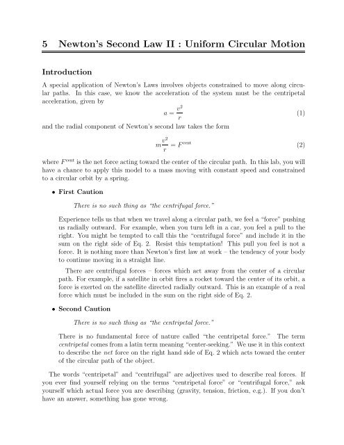
5 Newton’s <strong>Second</strong> <strong>Law</strong> <strong>II</strong> : <strong>Uniform</strong> <strong>Circular</strong> <strong>Motion</strong><br />
Introduction<br />
A special application of Newton’s <strong>Law</strong>s involves objects constrained to move along circular<br />
paths. In this case, we know the acceleration of the system must be the centripetal<br />
acceleration, given by<br />
a = v2<br />
r<br />
and the radial component of Newton’s second law takes the form<br />
(1)<br />
m v2<br />
r = Fcent (2)<br />
where F cent is the net force acting toward the center of the circular path. In this lab, you will<br />
have a chance to apply this model to a mass moving with constant speed and constrained<br />
to a circular orbit by a spring.<br />
• First Caution<br />
There is no such thing as “the centrifugal force.”<br />
Experience tells us that when we travel along a circular path, we feel a “force” pushing<br />
us radially outward. For example, when you turn left in a car, you feel a pull to the<br />
right. You might be tempted to call this the “centrifugal force” and include it in the<br />
sum on the right side of Eq. 2. Resist this temptation! This pull you feel is not a<br />
force. It is nothing more than Newton’s first law at work – the tendency of your body<br />
to continue moving in a straight line.<br />
There are centrifugal forces – forces which act away from the center of a circular<br />
path. For example, if a satellite in orbit fires a rocket toward the center of its orbit, a<br />
force is exerted on the satellite directed radially outward. This is an example of a real<br />
force which must be included in the sum on the right side of Eq. 2.<br />
• <strong>Second</strong> Caution<br />
There is no such thing as “the centripetal force.”<br />
There is no fundamental force of nature called “the centripetal force.” The term<br />
centripetal comes fromalatinterm meaning “center-seeking.” We use it inthiscontext<br />
to describe the net force on the right hand side of Eq. 2 which acts toward the center<br />
of the circular path of the object.<br />
The words “centripetal” and “centrifugal” are adjectives used to describe real forces. If<br />
you ever find yourself relying on the terms “centripetal force” or “centrifugal force,” ask<br />
yourself which actual force you are describing (gravity, tension, friction, e.g.). If you don’t<br />
have an answer, something has gone wrong.
Experiment<br />
The apparatus for this experiment allows you to measure all of the important characteristics<br />
of an object moving on a circular path at constant speed.<br />
1. Level the apparatus with a bubble level by adjusting the heights of the legs.<br />
2. Disconnect the spring from the mass and position the vertical metal pointer at the<br />
horizontal position at which the mass hangs at rest. Measure the distance of the mass<br />
(and the pointer) from the center of rotation of the apparatus. This is the radius of<br />
the circular path on which you would like the mass to travel during the experiment.<br />
3. Reconnect the spring, and use the string, pulley and mass hanger to measure the force<br />
exerted by the spring on the mass when it is at the position of the pointer. Think<br />
carefully about how to assign an uncertainty to this measurement. Hint : You may<br />
assume the numbers stamped on the masses are accurate to within 1 gram, but the<br />
uncertainty in the spring force is much larger than (1 g)(9.8 m/s 2 ) = 0.0098 N !<br />
4. Measure the mass of the “mass” itself.<br />
5. Spin the apparatus (by hand) up to the speed at which the mass hangs at the same<br />
radial distance from the axle as the pointer. Practice maintaining this speed.<br />
6. Now, measure the speed of the mass. You have been provided with a stopwatch for<br />
this measurement. Hint : If you measure the time it takes for the mass to complete<br />
several orbits, the relative uncertainty in your time measurement is smaller than if you<br />
only time a single orbit.<br />
7. The radius of the circular orbit is adjustable. Change the radius, adjust the counterweight<br />
to balance the apparatus, and make another measurement. Repeat until you<br />
have 5 measurements covering the available range of radii.<br />
Analysis<br />
1. Use Excel to create a graph of v2 vs. r Fcent . According to the model, the slope should<br />
be consistent with 1 within uncertainty.<br />
m<br />
2. If your data appears to be compatible with a linear model, then use the linest()<br />
function to perform a linear fit to the line (see Appendix B).<br />
3. Add the fit line to your graph.<br />
4. Calculate the uncertainty in one of your v2 values following the rules for the propagation<br />
of uncertainties (see Appendix A). (Ask for help if you need<br />
r<br />
it.)<br />
5. Compare the uncertainty you found in step 4 with the standard deviation in the y<br />
estimate (σ y ) from your linear fit. Add error bars to your graph corresponding to<br />
whichever uncertainty is larger.
Questions<br />
Show your spreadsheet including the graph showing the best fit line and error bars on the<br />
values to your instructor/TA and answer the following questions.<br />
v 2<br />
r<br />
1. Describehowyouestablishedtheuncertaintiesinyourspring-forcemeasurements(with<br />
the pulley and mass hanger).<br />
2. Describe how you determined the size of the error bars on the graph – both the error<br />
propagation and σ y approaches, and which one you chose.<br />
3. Comment on the agreement of the model with your measurements. Was your graph<br />
compatible with a linear model Was the slope consistent with the predicted value