SignaLink SL-1+ Installation & Operation Manual - Tigertronics
SignaLink SL-1+ Installation & Operation Manual - Tigertronics
SignaLink SL-1+ Installation & Operation Manual - Tigertronics

You also want an ePaper? Increase the reach of your titles
YUMPU automatically turns print PDFs into web optimized ePapers that Google loves.
• Verify Pin-out – This step is Extremely Important<br />
since not all manufacturers use the same numbering<br />
convention for their connectors. This is especially true<br />
of radios using RJ-45 mic connectors. This brief<br />
verification process could ward off a major disaster<br />
when you turn on the power! This procedure verifies<br />
that the pin numbers, which you just identified in the<br />
Operators <strong>Manual</strong>, do in fact match the numbers<br />
identified on the Programming Socket. The easiest way<br />
to do this is to use a multimeter to verify some of the<br />
more important lines. Before you start, you will need to<br />
make sure that the radio power is OFF, that there are<br />
NO JUMPERS are installed in JP-1, and that the<br />
supplied cable is connected between the <strong>SignaLink</strong> and<br />
the radio.<br />
Note that you should not find the lines “scrambled”.<br />
They will either be in the correct order or they will be<br />
completely reversed (pin 1=8, 2=7, 3=6, etc).<br />
First check the Ground pin (or pins) recorded earlier.<br />
You can do this by checking for continuity between the<br />
radio chassis and the pins numbered on the<br />
Programming Socket (JP-1). JP-1 is a very convenient<br />
place to probe since it is wired 1:1 to every pin on the<br />
radio connector. You will be checking against the<br />
numbers you recorded earlier from the Operators<br />
<strong>Manual</strong>. Note that if your radio has a separate mic<br />
ground it may have a slight resistance to chassis ground.<br />
Any other ground pin should test very close to zero<br />
ohms. If you do not get the expected continuity in this<br />
test, try checking against the numbers in the reverse<br />
order (1=8, 2=7, 3=6, etc). It would probably be very<br />
helpful to make a new table using the reversed number<br />
sequence to avoid mistakes! This step should establish<br />
whether or not the radio connector is “reverse ordered”<br />
and allow you to correct the numbers on your table.<br />
Once you are confident about the ground lines you can<br />
move on to other pins. If your radio had Accessory<br />
Power you should be able to turn ON the radio and use<br />
your multimeter (volts scale) to test for power on the<br />
appropriate pin of JP-1.<br />
There is no easy way to test the mic line but there will<br />
be little doubt about it if the other lines are correct. The<br />
main thing you are looking for here is to determine<br />
whether or not the connector numbers are reversed on<br />
your radio. If you have any unresolved errors, then you<br />
should double check your numbering in the Operators<br />
<strong>Manual</strong> again.<br />
G<br />
G<br />
G<br />
- - -<br />
PWR<br />
PTT<br />
MIC<br />
SPKR<br />
JP1<br />
Radio Connector<br />
8_______________________<br />
7_______________________<br />
6_______________________<br />
5_______________________<br />
4_______________________<br />
3_______________________<br />
2_______________________<br />
1_______________________<br />
Figure 2 – Jumper Wiring Diagram<br />
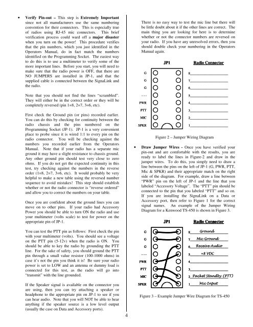
• Draw Jumper Wires - Once you have verified your<br />
pin-out and are comfortable with the results, you are<br />
ready to label the lines in Figure-2 and draw in the<br />
jumper wires. To do this, you simply need to draw a<br />
line between the pins on the left of JP-1 (G, PWR, PTT,<br />
Mic & SPKR) and their appropriate match on the right<br />
side of the diagram. For example, draw a line between<br />
“PWR” pin on the left of JP-1 and the line that you<br />
labeled “Accessory Voltage”. The “PTT” pin should be<br />
connected to the pin that you labeled “PTT” and so on.<br />
If you are installing the <strong>SignaLink</strong> on a Data or<br />
Accessory port, then refer to Figure 1 for the correct<br />
signal names. An example of the Jumper Wiring<br />
Diagram for a Kenwood TS-450 is shown in Figure 3.<br />
JP1<br />
Radio Connector<br />
You can test the PTT pin as follows: First check the pin<br />
with your multimeter (volts). You should see a voltage<br />
on the PTT pin (5-12v) when the radio is ON. You<br />
should be able to key the radio by grounding the PTT<br />
line. For the sake of safety, you should ground the PTT<br />
pin through a small value resistor (100-1000 ohms) in<br />
case it’s not the pin you think it is! Be sure your radio<br />
power is set to LOW and an antenna or dummy load is<br />
connected for this test, as the radio will go into<br />
“transmit” with the line grounded.<br />
G<br />
G<br />
G<br />
- - -<br />
PWR<br />
PTT<br />
MIC<br />
8_______________________<br />
Ground<br />
7_______________________<br />
Mic Ground<br />
6_______________________<br />
Receive Audio<br />
5_______________________<br />
+8 VDC<br />
4_______________________<br />
3_______________________<br />
2_______________________<br />
Packet Standby (PTT)<br />
If the Speaker signal is available on the connector you<br />
are using, then you can try attaching a speaker or<br />
headphone to the appropriate pin on JP-1 to see if you<br />
can hear audio. Note that you will NOT be able to hear<br />
anything if the speaker source is a low level output<br />
(usually the case on Data and Accessory ports).<br />
4<br />
SPKR<br />
1_______________________<br />
Mic Input<br />
Figure 3 – Example Jumper Wire Diagram for TS-450