SignaLink SL-1+ Installation & Operation Manual - Tigertronics
SignaLink SL-1+ Installation & Operation Manual - Tigertronics
SignaLink SL-1+ Installation & Operation Manual - Tigertronics

You also want an ePaper? Increase the reach of your titles
YUMPU automatically turns print PDFs into web optimized ePapers that Google loves.
<strong>SignaLink</strong> TM <strong>SL</strong>-<strong>1+</strong> Sound Card - Radio Interface<br />
Grants Pass, Oregon<br />
154 Hillview Drive Grants Pass, Oregon 97527<br />
(541) 474-6700 Fax: (541) 474-6703 Internet: http://www.tigertronics.com<br />
<strong>Installation</strong> & <strong>Operation</strong><br />
this manual. It covers most of the common problems that<br />
you might run into. Technical Support for the <strong>SignaLink</strong> is<br />
also available if you need it. Please see the “Technical<br />
Support” section of this manual for more information.<br />
- WHAT YOU WILL NEED -<br />
- INTRODUCTION -<br />
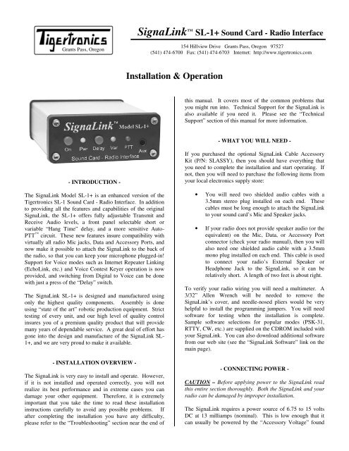
The <strong>SignaLink</strong> Model <strong>SL</strong>-<strong>1+</strong> is an enhanced version of the<br />
<strong>Tigertronics</strong> <strong>SL</strong>-1 Sound Card - Radio Interface. In addition<br />
to providing all the features and capabilities of the original<br />
<strong>SignaLink</strong>, the <strong>SL</strong>-<strong>1+</strong> offers fully adjustable Transmit and<br />
Receive Audio levels, a front panel selectable short or<br />
variable “Hang Time” delay, and a more sensitive Auto-<br />
PTT circuit. These new features insure compatibility with<br />
virtually all radio Mic jacks, Data and Accessory Ports, and<br />
now make it possible to attach the <strong>SignaLink</strong> to the back of<br />
the radio, so that you can keep your microphone plugged-in!<br />
Support for Voice modes such as Internet Repeater Linking<br />
(EchoLink, etc.) and Voice Contest Keyer operation is now<br />
provided, and switching from Digital to Voice can be done<br />
with just a press of the “Delay” switch.<br />
The <strong>SignaLink</strong> <strong>SL</strong>-<strong>1+</strong> is designed and manufactured using<br />
only the highest quality components. Assembly is done<br />
using “state of the art” robotic production equipment. Strict<br />
testing of every unit, and our high level of quality control<br />
insures you of a premium quality product that will provide<br />
many years of dependable service. A great deal of effort has<br />
gone into the design and manufacture of the <strong>SignaLink</strong> <strong>SL</strong>-<br />
<strong>1+</strong>, and we are very proud to make it available.<br />
- INSTALLATION OVERVIEW -<br />
The <strong>SignaLink</strong> is very easy to install and operate. However,<br />
if it is not installed and operated correctly, you will not<br />
realize its best performance and in extreme cases you can<br />
damage your other equipment. Therefore, it is extremely<br />
important that you take the time to read these installation<br />
instructions carefully to avoid any possible problems. If<br />
after completing the installation you have any difficulty,<br />
please refer to the “Troubleshooting” section near the end of<br />
If you purchased the optional <strong>SignaLink</strong> Cable Accessory<br />
Kit (P/N: <strong>SL</strong>ASSY), then you should have everything that<br />
you need to complete the installation and start operating. If<br />
not, then you will need to purchase the following items from<br />
your local electronics supply store:<br />
• You will need two shielded audio cables with a<br />
3.5mm stereo plug installed on each end. These<br />
cables must be long enough to attach the <strong>SignaLink</strong><br />
to your sound card’s Mic and Speaker jacks.<br />
• If your radio does not provide speaker audio (or the<br />
equivalent) on the Mic, Data, or Accessory Port<br />
connector (check your radio manual), then you will<br />
also need one shielded audio cable with a 3.5mm<br />
mono plug installed on each end. This cable is used<br />
to connect your radio’s External Speaker or<br />
Headphone Jack to the <strong>SignaLink</strong>, so it can be<br />
relatively short. A length of two feet is about right.<br />
To verify your radio wiring you will need a multimeter. A<br />
3/32” Allen Wrench will be needed to remove the<br />
<strong>SignaLink</strong>’s cover, and needle-nosed pliers would be very<br />
helpful to install the programming jumpers. You will need<br />
software for testing when the installation is complete.<br />
Sample software selections for popular modes (PSK-31,<br />
RTTY, CW, etc.) are supplied on the CDROM included with<br />
your <strong>SignaLink</strong>. You can also download additional software<br />
from our web site (see the “<strong>SignaLink</strong> Software” link on the<br />
main page).<br />
- CONNECTING POWER -<br />
CAUTION – Before applying power to the <strong>SignaLink</strong> read<br />
this entire section thoroughly. Both the <strong>SignaLink</strong> and your<br />
radio can be damaged by improper installation.<br />
The <strong>SignaLink</strong> requires a power source of 6.75 to 15 volts<br />
DC at 13 milliamps (nominal). This is low enough that it<br />
can usually be powered by the “Accessory Voltage” found
on the microphone or Accessory Port connector of most<br />
radios. If Accessory Voltage is not available from the radio,<br />
then power can be supplied through a 2.1mm power jack on<br />
the rear of the unit.<br />
Powering From Your Radio – To determine if the<br />
<strong>SignaLink</strong> can be powered from your radio, you will need to<br />
check the “pin-out” of the radio connector that you are going<br />
to attach the <strong>SignaLink</strong> to (Mic, Data, Accessory, etc.). This<br />
information can be found in your radio Operators <strong>Manual</strong>.<br />
Most radios have a small amount of power available on the<br />
mic jack (typically 8v @ 10ma) for microphone accessories<br />
(DTMF pad, LEDs, etc.). Power is also sometimes available<br />
on the Data or Accessory port. If your manual shows that<br />
this voltage is available, then you can skip now to the<br />
“Connecting The Radio” section of this manual. That<br />
section will cover making the actual power connection.<br />
If power is not available on the radio connector you are<br />
using, then you have a couple of other easy options for<br />
powering the <strong>SignaLink</strong>. The first option would be to obtain<br />
power from whatever 12 volt supply powers your radio. To<br />
do this you will need to make a short cable from that power<br />
supply to the external power jack on the back of the<br />
<strong>SignaLink</strong>. Note that you might also be able to obtain 12-<br />
volt power from an Accessory Voltage connector on the back<br />
of the radio (check your radio manual). The external power<br />
jack on the <strong>SignaLink</strong> requires a standard 2.1mm/5.5mm<br />
power plug. This plug has been included with the <strong>SignaLink</strong><br />
for your convenience. You will need to wire the plug to your<br />
power supply in the appropriate manner. The polarity of the<br />
plug should be center positive. Be sure to wire the plug<br />
with the correct polarity and be sure to install a fuse in the<br />
line for safety. For maximum protection, we recommend<br />
that you fuse BOTH the positive and negative power lines<br />
with a low current (250 ma or less) “fast blow” fuse.<br />
The second option for powering the <strong>SignaLink</strong> is to use a<br />
Wall Transformer. This is the quick and easy solution but it<br />
does require an outlet. If you choose this option, you will<br />
need to select a transformer with an appropriate rating. A<br />
common problem in selecting wall transformers is that they<br />
almost always put out more voltage than you expect. This is<br />
because they are rated for output voltage at a specific load<br />
current. If the load on the transformer is below the rated<br />
load, then the voltage output will be higher than the rated<br />
output. Under a light load, it is not uncommon for wall<br />
transformers to provide twice their rated output voltage!<br />
This means that a typical 12 volt transformer might put out<br />
as much as 25 volts under little or no load, which would<br />
exceed the <strong>SignaLink</strong> input voltage ratings. Because of the<br />
very light load (13ma) provided by the <strong>SignaLink</strong>, you will<br />
need to select a transformer with a rated voltage well under<br />
12 volts. We would recommend a 6 volt transformer with a<br />
low current rating. Below are some transformer sources that<br />
are appropriate.<br />
Radio Shack P/N 273-1758 (6v 300ma). You will also need<br />
the 2.1mm (5.5mm OD) adapter plug P/N 273-1716.<br />
Mouser Electronics (1-800-346-6873): P/N 412-106054.<br />
(6v 500ma). Mouser also has a 9 Volt 200ma wall<br />
transformer (P/N: 412-109024) that will work.<br />
Digikey (1-800-344-4539): P/N DPD090020-P-5 or<br />
DPD090020-P5-TC. These are both 9 Volt 200 ma units<br />
that will work fine.<br />
- CONNECTING THE SOUND CARD -<br />
The <strong>SignaLink</strong> connects to the sound card through two<br />
shielded audio cables with 3.5mm stereo connectors.<br />
Connect one cable from the jack labeled “Computer –<br />
SPKR” on the <strong>SignaLink</strong> to the jack labeled “Speaker<br />
Output” on your sound card. The Speaker Output jack will<br />
be Green if color-coded. Connect the other cable from the<br />
jack labeled “Computer – MIC” on the <strong>SignaLink</strong> to the<br />
“Microphone Input” jack on the sound card. This jack will<br />
be Pink or Red if color-coded.<br />
Note that if you normally have speakers connected to your<br />
sound card and want to keep them connected while the<br />
<strong>SignaLink</strong> is installed, then you will need to use a stereo “Y”<br />
adapter cable on the sound card output. We have supplied a<br />
“Y” adapter in our optional Cable Accessory Kit for your<br />
convenience. We do NOT recommend the use of a “Y”<br />
adapter unless you are using “amplified” (powered)<br />
speakers. Conventional speakers often times cause slight<br />
overloading of the sound card output, which can reduce the<br />
signal level available to the <strong>SignaLink</strong> and produce minor<br />
distortion. This distortion is generally not noticeable to your<br />
ear but can greatly impact the quality of some digital<br />
modulation signals like PSK-31. It is generally preferred not<br />
to leave the speakers connected unless they can be switched<br />
OFF when not in use. You will find most of the digital<br />
modulation schemes very loud and very annoying anyway!<br />
- CONNECTING THE RADIO -<br />
CAUTION – Before connecting the <strong>SignaLink</strong> to your radio,<br />
read this entire section thoroughly. Both the <strong>SignaLink</strong> and<br />
your radio can be damaged by improper installation.<br />
The <strong>SignaLink</strong> attaches to the radio through an 8-pin RJ-45<br />
connector located on the rear of the unit. A radio cable with<br />
the appropriate connector for your radio was supplied with<br />
the <strong>SignaLink</strong> for this purpose. One end of this cable plugs<br />
into the <strong>SignaLink</strong>’s “RADIO” connector, and the other end<br />
plugs into the radio’s Mic, Data, or Accessory Port<br />
connector. This cable brings all of the radio’s signal lines<br />
into the <strong>SignaLink</strong>, so that you can connect to any line that is<br />
required (see note below on connectors with more than eight<br />
pins). The <strong>SignaLink</strong> uses the radio’s Ground, PTT, Speaker<br />
Output, Mic Input, and Accessory Voltage lines. These are<br />
the signal names that you will find on a typical Mic<br />
connector. These signals are also available on most Data<br />
and Accessory ports, but they are often labeled differently.<br />
This will be covered in more detail below.<br />
2
Because the location of these signals on the radio connector<br />
varies from radio to radio, we have provided a<br />
“Programming Socket” inside the <strong>SignaLink</strong> (see JP-1 in<br />
Figure-4). The Programming Socket provides a convenient<br />
way to route the various signals to the correct pin on the<br />
radio connector. This is accomplished with “press-in”<br />
jumper wires so no soldering is required.<br />
Since the Programming Socket is a standard DIP-16 format,<br />
you can also use a Dip Header Module for programming<br />
rather than wires. This “module” approach requires<br />
soldering but does have the advantage that the resulting<br />
“module” can be quickly changed to re-configure for<br />
different radios. The Dip Headers are available from<br />
<strong>Tigertronics</strong> as part number “<strong>SL</strong>HEAD”, and from electronic<br />
suppliers like DigiKey (P/N A103-ND) and Mouser (P/N<br />
544-16PT-02).<br />
Signal Lines – Every installation requires connecting to at<br />
least three pins on the radio’s Mic, Data, or Accessory<br />
connector. On the Mic connector these are “Mic Input”,<br />
“PTT”, and “Ground”. On the Data or Accessory Port, these<br />
same basic signals are used, but they are usually labeled<br />
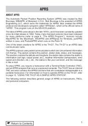
differently. The table in Figure 1 shows the common mic<br />
signals and their Data / Accessory port equivalents. Please<br />
refer to this table if you are installing the <strong>SignaLink</strong> on your<br />
radio’s Data or Accessory port.<br />
Mic Signal<br />
PTT (Push-To-Talk)<br />
Mic / Mic Input<br />
AF Out / Speaker<br />
PTT GND<br />
Mic GND<br />
Data/Accessory Port Signal<br />
Standby, PKS, or Packet Standby<br />
TX Data, Data Input, PKD, or<br />
Mod In<br />
RX Data, Data Out, RXD, or<br />
RX Audio<br />
PTT Ground, Chassis Ground<br />
Signal GND, Mic GND<br />
Figure 1 - Data / Accessory Port Signal Names<br />
Note that many radios actually have multiple ground<br />
connections (Mic Ground, PTT Ground, etc.). The<br />
Programming Socket has multiple ground (G) connections<br />
for this reason.<br />
On many radios the Mic, Data, and Accessory connectors<br />
also provide access to Supply Voltage and Speaker Audio.<br />
Supply Voltage has already been discussed in the section on<br />
“Connecting Power”. If your radio has power available on<br />
the connector then you will be instructed to connect it later in<br />
this section. If Speaker Audio (or the equivalent Data /<br />
Accessory Port signal) is not available from the connector on<br />
your radio, then you will need to install a short (mono)<br />
jumper cable from the External Speaker or Headphone jack<br />
on your radio to the SPKR jack on the rear panel of the<br />
<strong>SignaLink</strong>. If this signal is available on the connector, then<br />
you will connect it later in this section.<br />
Before proceeding with jumper installation you should verify<br />
in your radio manual that the radio PTT requirements do not<br />
exceed the specifications of the <strong>SignaLink</strong> keying circuit.<br />
3<br />
Verify that the PTT is “Grounded” to make the radio<br />
transmit and the PTT signal does not exceed 15 volts @<br />
75ma. This is well within the ratings of all modern radios<br />
but could be a problem on some older rigs. If your radio<br />
exceeds these specifications or requires some other keying<br />
arrangement, then you will need to key the radio using a low<br />
voltage/low current relay. Please feel free to contact<br />
Technical Support if you need assistance with this.<br />
Connectors With More Than Eight Pins – The jumper<br />
installation procedure in this manual is for use with radio<br />
connectors that have 8 pins or less. If you are installing the<br />
<strong>SignaLink</strong> on a 13-pin Accessory port (currently the only<br />
radio connector with more than eight pins), then you will<br />
either be using a fully assembled cable that we provided, or<br />
you will be attaching your own 13-pin connector to our unterminated<br />
cable. In either case, jumper settings and/or<br />
special instructions for installing the connector and jumpers<br />
were included with the radio cable. Please follow those<br />
instructions instead of the procedures in this manual.<br />
Jumper Settings – If printed jumper settings were supplied<br />
with your radio cable, then please skip to the “Install Jumper<br />
Wires” section, and install the jumpers as shown on the<br />
document. If you did not receive printed jumper settings<br />
with your radio cable, then please check the “Jumper<br />
Settings” section of the <strong>SignaLink</strong> CD to see if information<br />
for your radio is available. Jumper settings for the most<br />
common radios are included on the CD. If you do not find<br />
the jumpers settings for your radio, then you will need to<br />
follow the procedure below to install the jumpers.<br />
Identifying Jumper Locations - Identifying the jumper<br />
locations for your radio is a two-step process. First we will<br />
identify the pin-out for the radio connector, and then we will<br />
verify that it is correct. The verification process is very<br />
important since incorrect wiring could damage your<br />
equipment. The final steps will be to draw a wiring diagram<br />
using Figure-2 and actually install the jumpers.<br />
• Lookup Pin-out – In your radio Operators <strong>Manual</strong>, find<br />
the page that identifies the pin-out of the Mic, Data, or<br />
Accessory connector that you are going to use. Using<br />
the manual, identify the pin numbers assigned to the<br />
following signals, and record them below. Note that the<br />
signals found on radio Data and Accessory ports will<br />
likely be labeled differently from those shown. Please<br />
refer to the table in Figure 1 for the equivalent Data /<br />
Accessory Port signals.<br />
____ PTT<br />
____ Mic Input<br />
____ Speaker Audio<br />
____ Accessory Voltage<br />
____ Mic Ground**<br />
____ PTT Ground**<br />
____ Chassis Ground**<br />
** Note that some radios only have one ground pin.<br />
** Speaker and Accy Power are not always available.
• Verify Pin-out – This step is Extremely Important<br />
since not all manufacturers use the same numbering<br />
convention for their connectors. This is especially true<br />
of radios using RJ-45 mic connectors. This brief<br />
verification process could ward off a major disaster<br />
when you turn on the power! This procedure verifies<br />
that the pin numbers, which you just identified in the<br />
Operators <strong>Manual</strong>, do in fact match the numbers<br />
identified on the Programming Socket. The easiest way<br />
to do this is to use a multimeter to verify some of the<br />
more important lines. Before you start, you will need to<br />
make sure that the radio power is OFF, that there are<br />
NO JUMPERS are installed in JP-1, and that the<br />
supplied cable is connected between the <strong>SignaLink</strong> and<br />
the radio.<br />
Note that you should not find the lines “scrambled”.<br />
They will either be in the correct order or they will be<br />
completely reversed (pin 1=8, 2=7, 3=6, etc).<br />
First check the Ground pin (or pins) recorded earlier.<br />
You can do this by checking for continuity between the<br />
radio chassis and the pins numbered on the<br />
Programming Socket (JP-1). JP-1 is a very convenient<br />
place to probe since it is wired 1:1 to every pin on the<br />
radio connector. You will be checking against the<br />
numbers you recorded earlier from the Operators<br />
<strong>Manual</strong>. Note that if your radio has a separate mic<br />
ground it may have a slight resistance to chassis ground.<br />
Any other ground pin should test very close to zero<br />
ohms. If you do not get the expected continuity in this<br />
test, try checking against the numbers in the reverse<br />
order (1=8, 2=7, 3=6, etc). It would probably be very<br />
helpful to make a new table using the reversed number<br />
sequence to avoid mistakes! This step should establish<br />
whether or not the radio connector is “reverse ordered”<br />
and allow you to correct the numbers on your table.<br />
Once you are confident about the ground lines you can<br />
move on to other pins. If your radio had Accessory<br />
Power you should be able to turn ON the radio and use<br />
your multimeter (volts scale) to test for power on the<br />
appropriate pin of JP-1.<br />
There is no easy way to test the mic line but there will<br />
be little doubt about it if the other lines are correct. The<br />
main thing you are looking for here is to determine<br />
whether or not the connector numbers are reversed on<br />
your radio. If you have any unresolved errors, then you<br />
should double check your numbering in the Operators<br />
<strong>Manual</strong> again.<br />
G<br />
G<br />
G<br />
- - -<br />
PWR<br />
PTT<br />
MIC<br />
SPKR<br />
JP1<br />
Radio Connector<br />
8_______________________<br />
7_______________________<br />
6_______________________<br />
5_______________________<br />
4_______________________<br />
3_______________________<br />
2_______________________<br />
1_______________________<br />
Figure 2 – Jumper Wiring Diagram<br />
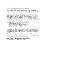
• Draw Jumper Wires - Once you have verified your<br />
pin-out and are comfortable with the results, you are<br />
ready to label the lines in Figure-2 and draw in the<br />
jumper wires. To do this, you simply need to draw a<br />
line between the pins on the left of JP-1 (G, PWR, PTT,<br />
Mic & SPKR) and their appropriate match on the right<br />
side of the diagram. For example, draw a line between<br />
“PWR” pin on the left of JP-1 and the line that you<br />
labeled “Accessory Voltage”. The “PTT” pin should be<br />
connected to the pin that you labeled “PTT” and so on.<br />
If you are installing the <strong>SignaLink</strong> on a Data or<br />
Accessory port, then refer to Figure 1 for the correct<br />
signal names. An example of the Jumper Wiring<br />
Diagram for a Kenwood TS-450 is shown in Figure 3.<br />
JP1<br />
Radio Connector<br />
You can test the PTT pin as follows: First check the pin<br />
with your multimeter (volts). You should see a voltage<br />
on the PTT pin (5-12v) when the radio is ON. You<br />
should be able to key the radio by grounding the PTT<br />
line. For the sake of safety, you should ground the PTT<br />
pin through a small value resistor (100-1000 ohms) in<br />
case it’s not the pin you think it is! Be sure your radio<br />
power is set to LOW and an antenna or dummy load is<br />
connected for this test, as the radio will go into<br />
“transmit” with the line grounded.<br />
G<br />
G<br />
G<br />
- - -<br />
PWR<br />
PTT<br />
MIC<br />
8_______________________<br />
Ground<br />
7_______________________<br />
Mic Ground<br />
6_______________________<br />
Receive Audio<br />
5_______________________<br />
+8 VDC<br />
4_______________________<br />
3_______________________<br />
2_______________________<br />
Packet Standby (PTT)<br />
If the Speaker signal is available on the connector you<br />
are using, then you can try attaching a speaker or<br />
headphone to the appropriate pin on JP-1 to see if you<br />
can hear audio. Note that you will NOT be able to hear<br />
anything if the speaker source is a low level output<br />
(usually the case on Data and Accessory ports).<br />
4<br />
SPKR<br />
1_______________________<br />
Mic Input<br />
Figure 3 – Example Jumper Wire Diagram for TS-450
VERY IMPORTANT NOTE! – You are about to install<br />
the jumper wires. The wires must be 24ga AWG or you<br />
will damage the socket! It would be best to use the<br />
wires that we provided for this purpose to avoid<br />
damage.<br />
• Install Jumper Wires – Now that you know where the<br />
jumper wires go, all you need to do is install them! This<br />
is best done by gripping them close to the end with<br />
needle-nosed pliers. When pushing the wires into the<br />
socket, be very careful not to bend them back and forth<br />
or they might break. If you break a wire off in the<br />
socket, there is no way to remove it. You will have to<br />
have a new socket installed! This should not be an issue<br />
if you are just a little bit careful. If you plan to change<br />
the socket configuration often for different radios, you<br />
might prefer to use a Dip Header for programming,<br />
rather than wires. The Dip Header is a small terminal<br />
block that you can solder the wires onto and then simply<br />
plug into JP-1 when it’s finished. This is by far the best<br />
method if you need to switch radios often. The Dip<br />
Headers are available from <strong>Tigertronics</strong> as part number<br />
“<strong>SL</strong>HEAD”, and from electronic suppliers like DigiKey<br />
(P/N A103-ND) and Mouser (P/N 544-16PT-02).<br />
Once you have all of the jumpers installed, take a minute<br />
to look them over. You might want to compare your<br />
jumper settings to the sample settings shown in the<br />
“Jumper Settings” section of the <strong>SignaLink</strong> CDROM.<br />
NOTE: If you are using the external “SPKR” or<br />
“PWR” input jacks on the rear of the <strong>SignaLink</strong>, then<br />
you should NOT have any jumpers going to the “SPKR”<br />
or “PWR” pins on JP-1.<br />
• Measure Accessory Voltage – This step is normally<br />
not necessary. But, if you have wired the accessory<br />
power from your radio and are not sure if it is adequate<br />
to power the <strong>SignaLink</strong>, then you can easily verify the<br />
voltage. First make sure the pc board is on an insolated<br />
surface (no metal or wire clippings under board!). Turn<br />
on the radio and press the Power switch on the<br />
<strong>SignaLink</strong>. The green Power led should illuminate.<br />
Using your multimeter (volts) verify the voltage between<br />
chassis ground and test point TP-1 near the left rear<br />
corner of the <strong>SignaLink</strong> pc board (Figure-4). The<br />
voltage should be at least 6.75 volts for proper<br />
operation. If the voltage is not adequate, then you will<br />
need to remove the Power jumper on JP-1 and power the<br />
unit externally (see “Connecting Power”).<br />
JP2 JP1 TP1<br />
Delay Ctrl RX Level Ctrl TX Level Ctrl<br />
Figure 4 – Location of TP1, JP1, JP2 and the TX, RX, and<br />
Level controls.<br />
- AUXILIARY AUDIO OUTPUT –<br />
The <strong>SignaLink</strong> has an Auxiliary Audio Output jack on the<br />
front panel that can be used to attach an external radio<br />
speaker or headphones for monitoring receiver audio. Inside<br />
the <strong>SignaLink</strong> we have provided jumper JP-2 to allow you to<br />
select when the external audio jack is active. By default we<br />
have jumpered both positions on JP-2 which makes the audio<br />
available all of the time. However, you can move the<br />
jumpers to allow the jack to be active only when the<br />
<strong>SignaLink</strong> is ON or OFF. To make the jack active when the<br />
unit is ON, jumper pins 1 & 2. To make the jack active<br />
when the unit is OFF, jumper pins 3 & 4. For example, if<br />
you only install the jumper on pins 3 & 4, the audio jack will<br />
only be active when the <strong>SignaLink</strong> is OFF. This is a nice<br />
way to mute the speaker when you are working the digital<br />
modes! Note that if your radio has audio on the mic<br />
connector, you can also use the rear panel SPKR connector<br />
for an external speaker. This jack is wired directly to the<br />
SPKR pin on JP-1.<br />
NOTE: Attaching or removing an external speaker while<br />
you are using the <strong>SignaLink</strong> will change the loading on the<br />
radio’s speaker circuit. This will probably cause a change in<br />
the level of audio going to the sound card, and may require<br />
you to re-adjust the audio level to compensate.<br />
- SETTING THE AUDIO LEVELS -<br />
(QUICK PROCEDURE!)<br />
5<br />
Before you operate your <strong>SignaLink</strong> on the air, you will need<br />
to adjust your soundcard and radio Receive and Transmit<br />
Audio levels. Incorrect adjustment of these levels can cause<br />
poor performance or unreliable operation. This procedure<br />
tells you how the levels should be set. It assumes you<br />
already know how to use your computer to set sound card
levels. If you are not familiar with setting the sound card<br />
levels, then please refer to the “Detailed Procedure” for<br />
doing this in the back of this manual.<br />
Before you can adjust the audio levels, the <strong>SignaLink</strong> must<br />
be connected to the sound card and radio. Both the<br />
<strong>SignaLink</strong> and the radio should be powered ON and a<br />
communications program that you have selected should<br />
already be installed on your computer. Note that you will be<br />
using the communications program to generate the audio<br />
tones that are used to adjust the level controls, so CW<br />
programs should NOT be used unless they have a continuous<br />
"Tune" mode. A PSK-31 program like DigiPan is ideal for<br />
making these adjustments.<br />
Transmit Audio Adjustment<br />
• If the <strong>SignaLink</strong> is connected to your radio’s Mic jack,<br />
then set your radio to USB. If the <strong>SignaLink</strong> is<br />
connected to a Data or Accessory Port, then you will<br />
need to set your radio to the appropriate mode for this<br />
type of connection. USB will work on some radios, but<br />
you may need to select a special mode such as “Data”,<br />
“User”, or “D-USB”. If you are not sure which mode to<br />
use, then consult your radio manual.<br />
• If the <strong>SignaLink</strong> is connected to your radio’s Mic jack,<br />
then turn the radio’s Mic Gain control all the way down<br />
so that there will not be any transmit power. If the<br />
<strong>SignaLink</strong> is connected to a Data or Accessory Port,<br />
then the Mic Gain control may not have any effect on<br />
the power output (consult your radio manual). If this is<br />
the case with your radio, then you will need to turn<br />
down the radio’s “Forward Power” control instead.<br />
Otherwise, you should set this control to provide<br />
maximum power. Note that the “Forward Power”<br />
control might be labeled “RF Power” or “Carrier<br />
Power” on your radio.<br />
• Your radio’s Speech Processor / Compressor and VOX<br />
features should be turned OFF.<br />
• Select “TUNE” in your communications program. Open<br />
the Windows “Volume Control Panel” and select<br />
“Playback” controls. Make sure that the “Master<br />
Volume” (far left volume control) and “Wave Volume”<br />
controls are NOT muted. The “Microphone” control<br />
(under Playback ONLY!) MUST be muted.<br />
• Adjust the “Master Volume” control for 75% of full<br />
volume. Next, set the “Wave Volume” control to zero<br />
and then advance it slowly noting the point where the<br />
<strong>SignaLink</strong>’s PTT LED turns ON. This “ON” point is<br />
the absolute minimum level needed to switch the<br />
<strong>SignaLink</strong> into Transmit, so we will need to increase the<br />
level further to insure reliable operation. Increase the<br />
Wave control to a point about 50% higher than the point<br />
where PTT activates.<br />
• If the <strong>SignaLink</strong> is connected to your radio’s Mic jack,<br />
then you should now be able to adjust the radio’s Mic<br />
Gain control for the desired transmit power level (see<br />
important note below BEFORE making final<br />
6<br />
adjustments to your transmit power!). If you cannot<br />
get adequate power by adjusting the Mic Gain control,<br />
then you may need to set both the Master and Wave<br />
volume controls higher (if possible), or adjust the<br />
<strong>SignaLink</strong>’s internal “TX Level” control for more output<br />
(see “TX Level and RX Level Controls” at the end of<br />
this section).<br />
• If the <strong>SignaLink</strong> is connected to a Data or Accessory<br />
Port, then the Mic Gain control may not affect power<br />
output. In this case, you will need to adjust the radio’s<br />
transmit power output by setting both the Master and<br />
Wave volume controls higher, or by adjusting the<br />
<strong>SignaLink</strong>’s internal “TX Level” control for more output<br />
(see “TX Level and RX Level Controls” at the end of<br />
this section). Your radio might also have a Data or<br />
Accessory Port gain control that can be increased to<br />
provide more power out (usually through a radio menu<br />
setting – check your radio manual). Be sure to read the<br />
important note below BEFORE making final<br />
adjustments to your transmit power!<br />
• Be sure to turn your program’s “TUNE” function OFF<br />
when you are finished making adjustments. If the PTT<br />
LED never turns ON, then you need to set your Master<br />
and Wave controls higher. If it still fails to turn ON, or<br />
if you cannot reach the desired transmit power level,<br />
then see the Troubleshooting section of this manual for<br />
possible causes.<br />
• IMPORTANT - Before you set your transmit power<br />
level, you need to check your radio manual and find out<br />
what the recommended maximum transmit level and<br />
duty cycle are. Most digital modes are similar to RTTY<br />
(100% duty cycle) and cannot be run at full power<br />
without damaging your radio. Also, some modes (like<br />
PSK-31) typically only require 25 watts or less for<br />
reliable communication. You can actually “swamp” out<br />
other users if you use too much power.<br />
Receive Audio Adjustment<br />
• Open the Windows “Volume Control Panel” and select<br />
“Recording Controls”. The “Master Volume” (if<br />
available) and “Microphone Volume” controls should be<br />
“Selected” (check box). Set the “Master Volume” (if<br />
available) and the “Microphone Volume” controls to<br />
50%. These settings should be adequate for normal<br />
operation.<br />
• If the <strong>SignaLink</strong> is attached your radio’s Mic jack, then<br />
all further adjustment of the Receive Audio level should<br />
be done with the radio’s Volume control. If you are not<br />
able to get an adequate amount of Receive Audio with<br />
these settings, then you can set the sound card Mic<br />
volume control higher, or adjust the <strong>SignaLink</strong>’s internal<br />
“RX Level” control for more output (see “TX Level and<br />
RX Level Controls” at the end of this section).<br />
• If the <strong>SignaLink</strong> is attached your radio’s Data or<br />
Accessory Port, then all further adjustment of the<br />
Receive Audio level should be done with the sound<br />
card’s Mic volume control, or the <strong>SignaLink</strong>’s internal
“RX Level” control (see “TX Level and RX Level<br />
Controls” at the end of this section).<br />
• If you are unable to get an adequate Receive Audio<br />
level, then please see the Troubleshooting section of this<br />
manual.<br />
- TX LEVEL AND RX LEVEL CONTROLS -<br />
IMPORTANT - Do not attempt to adjust these controls until<br />
after you have completed either the “Quick” audio level<br />
setting procedure, or the more detailed procedure in the<br />
back of this manual. The TX Level and RX Level controls do<br />
NOT need to be adjusted for most installations.<br />
The <strong>SignaLink</strong>’s TX Level and RX Level controls allow you<br />
to adjust the Transmit Audio level going to the radio, and the<br />
Receive Audio level going to the sound card. The factory<br />
default setting for both of these controls is fully counterclockwise<br />
(minimum) and is ideal for most installations.<br />
However, some equipment combinations may require more<br />
audio than the factory settings provide. If you have<br />
completed the audio level setting procedure, and cannot get<br />
adequate Transmit power or Receive Audio, then you can<br />
adjust these controls to provide the correct level for your<br />
installation. The location of these controls is shown in<br />
Figure 4. To increase the level, simply turn the control<br />
clockwise. We recommend that you use the proper trimmer<br />
adjustment tool to do this, but a small jewelers type<br />
screwdriver can be used instead.<br />
NOTE: The “TX Level” control does NOT affect the<br />
operation of the <strong>SignaLink</strong>’s PTT circuit. If you cannot get<br />
the PTT LED to turn ON, it has nothing to do with the TX<br />
Level adjustment. You should NOT adjust the TX Level<br />
control until the sound card levels have been set properly and<br />
the <strong>SignaLink</strong> is switching to Transmit. See the<br />
Troubleshooting section of this manual if you need<br />
assistance with this problem.<br />
- GENERAL RADIO SETTINGS -<br />
Virtually all digital modes require that you TURN OFF any<br />
Speech Processing or Compression features in your radio.<br />
This is to insure RF linearity. You must also TURN OFF<br />
your VOX circuit when using the <strong>SignaLink</strong>. As mentioned<br />
in the sound card level settings procedure, you can usually<br />
use your radio’s USB mode for digital operation (LSB for<br />
some bands). However, if the <strong>SignaLink</strong> is connected to a<br />
Data or Accessory Port, then you may need to select a<br />
special mode such as “Data”, “User”, “D-USB” or “D-LSB”<br />
(to name a few). If you are not sure which mode to use, then<br />
consult your radio manual.<br />
- SIGNALINK OPERATION -<br />
<strong>Operation</strong> of the <strong>SignaLink</strong> is very simple. The <strong>SignaLink</strong>’s<br />
“receive” circuitry is active at all times, so you do not need<br />
to turn it ON to receive signals through it. The “transmit”<br />
circuitry is only active when the unit is turned “ON”. When<br />
active, the <strong>SignaLink</strong> will trigger your radio’s PTT whenever<br />
it sees sound card activity, so it is important to keep it turned<br />
“OFF” when it is not in use to prevent accidental<br />
transmissions. If you are using your computer solely for<br />
Digital operation, you might want to consider disabling your<br />
Windows sounds.<br />
Delay Switch - The front panel “Delay” switch is used to<br />
control the Transmit “Hang Time” for the <strong>SignaLink</strong>’s Auto-<br />
PTT circuit. With the Delay switch OUT, the radio will<br />
remain keyed for approximately 30 milliseconds after<br />
Transmit Audio from the sound card has stopped. This<br />
setting is suitable for CW QSK operation, and other modes<br />
that require fast turn-around times like Packet. It is also the<br />
best position for many other digital modes like PSK-31 and<br />
MT63.<br />
With the Delay switch pressed IN, the “Var” LED on the<br />
<strong>SignaLink</strong>’s front panel will turn ON to indicate that the<br />
variable Hang Time delay is selected. In this position, the<br />
Hang Time delay can be adjusted from approximately 300ms<br />
to 3 seconds, by means of an internal “Delay” control (see<br />
Figure 4 for location). The factory default setting for this<br />
control is approximately two seconds, which is adequate for<br />
most Voice modes such as Internet Repeater Linking,<br />
Remote Base operation, and Voice Contest Keyers. For<br />
slow AFSK CW, you will probably want to decrease the<br />
Hang Time delay to between 500 ms and 1 second.<br />
- VISIT US ON THE INTERNET -<br />
If you have Internet access, please visit our web site at:<br />
http://www.tigertronics.com<br />
Our site contains the latest news about <strong>Tigertronics</strong>’<br />
products, support information, and other information of<br />
interest to all Hams and SWLs. This is also the best source<br />
for downloadable programs that work with our products. We<br />
also have all of our distribution software and documentation<br />
available for download as well. The site is updated often, so<br />
stop in on a regular basis and get the latest news and updates.<br />
- YOUR COMMENTS WELCOME -<br />
We have made every effort to make the <strong>SignaLink</strong> the best<br />
product possible. We welcome any comments or<br />
suggestions that you would like to make. Please drop us a<br />
note to let us know about your experiences, tips you would<br />
like to share with other users, or how we might do a better<br />
job for you.<br />
7
- LIMITED WARRANTY -<br />
<strong>Tigertronics</strong> warrants the <strong>SignaLink</strong> to be free of defects in<br />
material and workmanship for a period of 90 days from the<br />
date of shipment. <strong>Tigertronics</strong> will repair or replace, at its<br />
option, any parts found to be defective during the warranty<br />
period. This warranty does not include any unit that has<br />
been subject to misuse, neglect, improper installation or<br />
operation. This warranty is in lieu of all others, express or<br />
implied, and no person or representative is authorized to<br />
assume for <strong>Tigertronics</strong> any other liability in connection with<br />
the sale or use of this product. <strong>Tigertronics</strong> will not be<br />
responsible for any expense or loss of revenue or property<br />
incurred by the user due to operation or malfunction of this<br />
equipment. <strong>Tigertronics</strong> reserves the right to make circuit or<br />
component changes, or to incorporate new features, at any<br />
time, without obligation.<br />
more expensive, but more can be accomplished in a few<br />
minutes on the phone than can be done in hours of writing!<br />
Power Supply:<br />
Freq Response:<br />
In / Out Impedance:<br />
Attenuation:<br />
Auto-PTT Delay:<br />
- GENERAL SPECIFICATIONS -<br />
6.75 - 15 VDC @ 13 ma (nom)<br />
100Hz - 30KHz<br />
600 ohm<br />
Radio To Sound Card: Variable<br />
Sound Card to Radio: Variable<br />
Fast (OUT) – 30 ms<br />
Variable (IN) – 300 ms to 3 sec<br />
- RETURN POLICY -<br />
PTT Circuit:<br />
MOSFET Transistor<br />
Rating - 15v @ 75 ma (Max)<br />
A Return Material Authorization Number (RMA#) must be<br />
obtained before any product will be accepted for return or<br />
repair. Items received without an RMA# clearly marked on<br />
the OUTSIDE of the package WILL BE REFUSED. Items<br />
being returned must be sent prepaid. Returned items should<br />
have a note attached showing the RMA#, customer name,<br />
return address, phone number, and action requested. Units<br />
being returned for warranty repair must be accompanied by a<br />
copy of the original sales invoice showing the date of<br />
purchase.<br />
Customers wishing to return a product for REFUND, for<br />
ANY REASON, must receive an RMA# within 15 days from<br />
the shipping date shown on the original sales invoice.<br />
Customers returning products for refund will be charged a<br />
Restocking Fee equal to 20% of the purchase price, to cover<br />
the cost of re-testing and re-stocking. Products that have<br />
been damaged or modified in any way may not be returned.<br />
Contact our Technical Support department for the RMA#.<br />
Radio Connector:<br />
Sound Card Conn:<br />
Other Connectors:<br />
Case:<br />
Mic, Spkr, Pwr, PTT - RJ-45<br />
Spkr - 3.5mm Mono<br />
Mic/Spkr - 3.5mm Stereo<br />
Aux. Spkr - 3.5mm Mono<br />
Aux. Power - 2.1mm Coaxial<br />
Extruded Aluminum - 6061T4<br />
Dimensions: 1.1” x 2.7” x 3.2”<br />
Operating Temp: -30C to +60C<br />
- TECHNICAL SUPPORT -<br />
BEFORE YOU CALL – The vast majority of technical<br />
issues can be resolved with the information that is available<br />
in this manual and on the <strong>Tigertronics</strong> web site. If you<br />
thoroughly investigate these resources, you will probably<br />
never need to call. Please take some time to read through<br />
this manual, and then check the online support resources to<br />
be sure that you have the most current software and<br />
documentation available. Thank you.<br />
If you encounter a problem that you cannot resolve with the<br />
<strong>SignaLink</strong> (not software), please contact our Technical<br />
Support Staff at (541) 862-2639. They are available every<br />
Monday, Wednesday, and Friday, from 1:00 PM to 5:00<br />
PM Pacific Time. Be sure to have your equipment available<br />
for testing when you call. Please DO NOT mail, email, or<br />
fax your technical inquiries. We realize that calling is a little<br />
8
Troubleshooting and Detailed Adjustment Procedures<br />
- TROUBLESHOOTING -<br />
These are the most common problems as reported by our<br />
Technical Support Staff. If you do not find your problem<br />
listed here, or if you are unable to resolve the problem, then<br />
please refer to the Technical Support section of this manual<br />
for instructions on contacting Technical Support.<br />
Radio doesn’t transmit AND the <strong>SignaLink</strong>'s PTT LED<br />
is OFF - It is important to remember that the <strong>SignaLink</strong> keys<br />
the radio automatically when it detects transmit audio. If the<br />
PTT LED on the <strong>SignaLink</strong> is OFF, then it is most likely<br />
because the signal from the soundcard’s speaker output is not<br />
getting to the <strong>SignaLink</strong>, or because the signal level is too<br />
low. Please check the following:<br />
• Sound card not functioning properly - If you are not<br />
sure that your sound card is functioning correctly, then<br />
you should perform the soundcard test following this<br />
section.<br />
• Sound card levels set too low – Repeat the procedure<br />
for setting the sound card audio levels. If this does not<br />
resolve the problem, then set the Master Volume control<br />
to 90-95% of full volume (instead of 75%), and try<br />
again. If a higher volume setting works, then you should<br />
find the lowest setting that works reliably, and then have<br />
a friend verify that your transmitted signal is<br />
undistorted.<br />
• Soundcards with Digital outputs – If your soundcard<br />
has digital outputs, then you will need to disable them<br />
for the <strong>SignaLink</strong> to work properly. Most digital<br />
outputs can be disabled by running the software that was<br />
supplied with the sound card, and selecting “Disable<br />
Digital Outputs”. If you are not sure how to do this,<br />
then please consult the instruction book that came with<br />
your soundcard or PC.<br />
• Sound card cables reversed – Make sure you have not<br />
reversed the mic/spkr cables to the sound card, and that<br />
they are plugged into the correct sound card jacks. The<br />
Speaker Output jack will be Green if color-coded, and<br />
the Mic Input jack will be Red or Pink. Most sound<br />
cards are poorly marked so you may need to refer to<br />
your computer’s manual to verify the correct jack<br />
location.<br />
Radio doesn’t transmit even though the <strong>SignaLink</strong>'s PTT<br />
LED is ON - If the <strong>SignaLink</strong>'s PTT LED turns ON but the<br />
radio doesn't switch to transmit, then you have jumpered the<br />
PTT signal incorrectly on JP-1. This should not be an issue<br />
if you tested the PTT line as outlined in the jumper section.<br />
If you find ANY jumper connected wrong then we<br />
recommend that you go through the entire jumper installation<br />
procedure again.<br />
9<br />
Radio transmits but there is no power output, or it is too<br />
low – Verify that your radio’s “Forward Power” (sometimes<br />
called “RF Power” or “Carrier Power”) control is set to<br />
maximum. If the <strong>SignaLink</strong> is attached to your radio’s Mic<br />
jack, then power is normally adjusted using the radios Mic<br />
Gain control. If this control is set to maximum and you are<br />
not able to obtain the desired transmit power level, then you<br />
may need to set the computer’s Master and Wave Playback<br />
controls higher, and/or adjust the <strong>SignaLink</strong>’s internal “TX<br />
Level” control for more output. If the <strong>SignaLink</strong> is attached<br />
to your radio’s Data or Accessory Port, then the Mic Gain<br />
control may not have any effect on the power output. If this<br />
is the case with your radio, then you will need to set the<br />
computer’s Master and Wave Playback controls higher (if<br />
possible), and/or adjust the <strong>SignaLink</strong>’s internal “TX Level”<br />
control for more output. You may also need to increase the<br />
Data/Accy Port gain on your radio. If available, this can be<br />
adjusted via a menu setting on most newer radios.<br />
My Transmit signal is “wide” or distorted – This is<br />
generally the result of over-driving your radio. Verify that<br />
your radio’s speech processor/compressor is turned OFF.<br />
Your radio’s “Forward Power” control (sometimes called<br />
“RF Power” or “Carrier Power”) should be set to maximum.<br />
If you have lowered this control to decrease your transmit<br />
power, then you more than likely have not set the audio<br />
levels correctly, and are overdriving your radio. Follow the<br />
“Setting The Audio Levels” procedure to correct this<br />
problem. If the above mentioned radio controls are set<br />
correctly, then try turning the mic gain down and see if that<br />
improves the quality of your signal. If the mic gain has no<br />
effect (this may be the case with a Data or Accessory Port<br />
connection), then you may have the software PlayBack<br />
volume controls, or the <strong>SignaLink</strong>’s TX Level control set to<br />
high. See the “Set Audio Levels” procedure to correct this.<br />
The <strong>SignaLink</strong> transmits when the radio volume is<br />
turned up (or tuned to a strong signal), or the <strong>SignaLink</strong><br />
flutters between Transmit and Receive – This problem is<br />
caused by an incorrect sound card mixer setting. To fix this<br />
problem, open the Windows Volume Control Panel. Select<br />
PlayBack Controls, and check the “Mute” check-box under<br />
the Microphone control. Be sure that you disable the Mic in<br />
PLAYBACK CONTROLS ONLY, or you will not be able to<br />
receive!<br />
I can't seem to receive - There are several possible causes<br />
for this problem:<br />
• Sound card not functioning properly - If you are not<br />
sure that your sound card is functioning correctly, then<br />
you should perform the Sound Card Test following this<br />
section.<br />
• The Microphone volume control is not selected - The<br />
“Select” check box for the Mic control (under<br />
RECORDING CONTROLS ONLY) should be checked.
• Sound card or radio level controls set too low -<br />
Because there are multiple controls that effect audio<br />
levels, it is very easy to have one set wrong. See the<br />
"Setting The Audio Levels" section of this manual to<br />
correct the problem.<br />
• Sound card cables reversed – Make sure you have not<br />
reversed the mic/spkr cables to the sound card, and that<br />
they are plugged into the correct sound card jacks. The<br />
Speaker Output jack will be Green if color-coded, and<br />
the Mic Input jack will be Red or Pink. Most sound<br />
cards are poorly marked so you may need to refer to<br />
your computer’s manual to verify the correct jack<br />
location.<br />
• Computer too slow or incompatible with software.<br />
Software not configured properly - Check the<br />
documentation for the program that you are using and<br />
verify that your computer meets the minimum<br />
requirements. Verify that the program is configured<br />
correctly and be sure that you are using it correctly. If<br />
all else fails, try using a different program.<br />
Why Can't I Receive Some Stations - No matter how good<br />
your antenna and radio are, there will always be some<br />
stations that you cannot copy (even with strong signals!).<br />
While the reason for this may be because of operator error<br />
(wrong mode or baud rate, off frequency, etc.), radio wave<br />
propagation problems can often prevent you from receiving.<br />
Some modes are more susceptible to this than others. For<br />
example, even though PSK31 usually works very well with<br />
weak signals, sometimes even strong PSK31 signals cannot<br />
be copied at all because of multipath and Doppler Shift<br />
propagation problems. Other modes like HF Packet and<br />
RTTY do not work well with weak signals and are<br />
susceptible to multipath and Doppler Shift.<br />
Microphone input. We will use your radios external speaker<br />
output for this purpose. Disconnect ALL CABLES from the<br />
<strong>SignaLink</strong> before you start this test.<br />
• Using a mono cable, connect the Speaker or Headphone<br />
output of your radio to the “SPKR” jack on the rear of<br />
the <strong>SignaLink</strong>. Be sure to use the jack that’s labeled<br />
“SPKR” (not the one labeled “Computer - SPKR”).<br />
• Using a stereo cable, connect the <strong>SignaLink</strong>’s<br />
“Computer - MIC” jack to your sound card’s<br />
Microphone input jack (not the Line Input). This jack<br />
will be Red or Pink if color-coded. Make sure no other<br />
cables are connected.<br />
Before we can record a signal, we need to adjust the radio<br />
and computer volume controls. Please note that the volume<br />
settings used here are for test purposes only. The controls<br />
will need to be re-adjusted later using the procedure found in<br />
the “Set Audio Levels” section of this manual. For now,<br />
adjust the audio level controls as follows:<br />
• Set your radio’s volume control to half of full volume.<br />
• Open the Windows Volume Control Panel by clicking<br />
on the Start Button and selecting Programs (or “All<br />
Programs”), Accessories, Multimedia (or<br />
“Entertainment”) and then Volume Control. The<br />
Volume Control panel should look similar to the one<br />
shown below:<br />
Windows "System Sounds" cause the <strong>SignaLink</strong> to<br />
transmit – Because the <strong>SignaLink</strong> is activated by sound card<br />
output, it is important that it is turned OFF when not in use.<br />
The sounds that are generated by Windows during different<br />
system events (Startup, Shutdown, File Close, etc.) can be<br />
transmitted if they are inadvertently sent to the <strong>SignaLink</strong>.<br />
Turn the <strong>SignaLink</strong> OFF when you’re done using it, or<br />
disable your Windows system sounds to avoid this issue.<br />
- TESTING YOUR SOUND CARD -<br />
If you are having unexplainable problems or are simply not<br />
sure if your sound card is working at all, you can use the<br />
following test procedure to verify sound card operation.<br />
This test uses the Sound Recorder program that comes with<br />
Windows to test your sound card’s record and playback<br />
functions. Before you begin the test, you need to verify that<br />
your computer speakers are plugged into the sound card and<br />
that all programs that use the sound card are closed.<br />
Figure 1 – Volume Control Panel<br />
• From the Options menu, select Properties to display the<br />
Properties page. In the “Adjust Volume For” window,<br />
select Playback.<br />
• In the “Show the following volume controls” window,<br />
verify that the Master Volume and Wave controls are<br />
selected. The Properties Page should look like the one<br />
shown in Figure-2. Note that the Master Volume<br />
control may be labeled “Volume Control”.<br />
To test the record function of the sound card, we need to<br />
have an audio source connected to the sound card's<br />
10
controls, and should look similar to the picture shown<br />
below.<br />
Figure 2 – Sample Properties Page<br />
• Click OK to close the properties page. The Playback<br />
volume controls should now be displayed.<br />
• Set the Master Volume and Wave controls to 1/2 of full<br />
volume. Verify that the Master Volume and Wave<br />
Level controls are NOT muted. The Balance controls<br />
should be left in their center position.<br />
• From the Options menu, select Properties to display the<br />
Properties page. In the “Adjust Volume For” window,<br />
select Recording.<br />
• In the “Show the following volume controls” window,<br />
verify that the Microphone box is checked. When you<br />
are done, the Properties Page should look similar to the<br />
one shown below.<br />
Figure 4 – Record Level Controls<br />
• Set the Sound Card’s Master Volume and Microphone<br />
Level controls to mid range. Verify that these controls<br />
are “Selected” by the Select check box below each<br />
control. If only one level control can be selected at a<br />
time, then select the Microphone input.<br />
NOTE: The Master Volume control may not be<br />
available on some computers.<br />
• Click on the X in the upper right-hand corner to close<br />
the Volume Control. Your new settings will be saved<br />
automatically.<br />
Now that the recording and playback controls are set to a<br />
usable level, we are ready to record and playback a test<br />
sound.<br />
• Start the Sound Recorder program by clicking on the<br />
Start Button and selecting Programs (or “All<br />
Programs”), Accessories, Multimedia (or<br />
“Entertainment”) and then Sound Recorder. The Sound<br />
Recorder program should look like the picture below.<br />
Note the location of the Record, Stop and Play buttons.<br />
Figure 3 – Record Properties<br />
• Click OK to close the properties page. The Volume<br />
Control panel should now show only the Recording<br />
Figure 5 – Sound Recorder Screen Shot<br />
11
• To begin recording, click the Record button. If<br />
everything is working correctly, you will see the position<br />
slider moving from left to right and the Position display<br />
incrementing. You should also see the scope display in<br />
the center of the program window track the audio<br />
signal. If nothing happens, or if you get an error<br />
message, then see the "Sound Card Problems" section<br />
below.<br />
• If everything appears to be working, then let the<br />
program record for a few seconds and then click the<br />
Stop button. We now have a test sound recorded that<br />
we can play back through the speakers.<br />
• To play the sound, click the Play button. You should<br />
hear the sound through your computer speakers. If you<br />
do, then you can close the Sound Recorder program.<br />
Your sound card is functioning correctly. If you don’t<br />
hear the sound playback, then you need to proceed to the<br />
"Sound Card Problems" section below.<br />
Sound Card Problems<br />
While <strong>Tigertronics</strong> does NOT provide support for sound<br />
card problems, we have listed a few troubleshooting tips here<br />
to help you with some of the most common problems. If you<br />
are unable to resolve a problem with your sound card, then<br />
you will need to contact your computer’s manufacturer or a<br />
computer repair shop for help.<br />
• If the record and playback features of the Sound<br />
Recorder program seem to work, but no sound is ever<br />
heard (or seen on the scope display), then check the<br />
level controls. You might have one of the volume<br />
controls muted, de-selected or set too low. If the<br />
volume controls look ok, then check your cabling.<br />
Verify that the cables have the right type of connector<br />
installed (3.5mm stereo) and are plugged into the right<br />
jacks. If you are using amplified speakers, verify that<br />
they are turned ON.<br />
buttons to be disabled until after you have recorded a<br />
sound.<br />
- SETTING THE AUDIO LEVELS -<br />
(DETAILED PROCEDURE)<br />
This is a “Step-By-Step” procedure to assist those who are<br />
not already familiar with setting sound card levels using the<br />
Windows Volume Control Panel. Before you operate your<br />
<strong>SignaLink</strong> on the air, you will need to adjust the Receive and<br />
Transmit Audio levels. Incorrect adjustment of these levels<br />
can cause poor reception, over-modulation, or improper<br />
operation. This procedure will show you how to adjust your<br />
sound card and radio audio levels for optimum performance.<br />
Before you can adjust the audio levels, the <strong>SignaLink</strong> must<br />
be connected to the sound card and radio. Both the<br />
<strong>SignaLink</strong> and the radio should be powered ON and a<br />
communications program that you have selected should<br />
already be installed on your computer. Note that we will be<br />
using the communications program to generate the audio<br />
tones that are used to adjust the level controls, so CW<br />
programs should NOT be used unless they have a continuous<br />
"Tune" mode. A program like DigiPan is ideal.<br />
Transmit Audio<br />
Follow the steps below to set your transmit audio level.<br />
• Start the communication program and leave it in<br />
Receive mode.<br />
• Open the Windows Volume Control Panel by clicking<br />
on the Start Button and selecting Programs (or “All<br />
Programs”), Accessories, Multimedia (or<br />
“Entertainment”) and then Volume Control. The<br />
Volume Control panel should look similar to the one<br />
shown in Figure-6.<br />
• If you receive an error message when you click the<br />
Record or Play button, then you need to verify that all<br />
other programs that use the sound card are closed.<br />
Problems can occur if more than one program tries to<br />
access the sound card at one time. If all of the other<br />
sound card programs are closed and you still receive an<br />
error message when you click the Record or Play button,<br />
then your sound card or its drivers may not be installed<br />
correctly. Refer to the instructions that came with your<br />
sound card (or computer) to re-install the card and / or<br />
drivers.<br />
• If all of the Sound Recorder control buttons (Record,<br />
Play, etc.) are disabled, then your sound card drivers are<br />
probably not installed correctly. Refer to the<br />
instructions that came with your sound card (or<br />
computer) to re-install the card and /or drivers. Note<br />
that it is normal for the Play, Rewind and Fast Forward<br />
12<br />
Figure 6 – Volume Control Panel<br />
• From the Options menu, select Properties to display the<br />
Properties page. In the “Adjust Volume For” window,<br />
select Playback.
• In the “Show the following volume controls” window,<br />
verify that the Master Volume and Wave level controls<br />
are selected. When you are done, the Properties Page<br />
should look like the one shown in Figure-7.<br />
NOTE: The Master Volume control may be simply<br />
labeled “Volume Control”.<br />
Figure 7 – Playback Properties<br />
• Click OK to close the Properties page.<br />
• Set the sound card’s Master Volume control to<br />
approximately 75% of full volume. Set the sound card’s<br />
Wave level control to minimum.<br />
• The Balance controls should be left at their center<br />
position.<br />
• Verify that the Master Volume and Wave level controls<br />
are NOT muted (check box).<br />
• Verify that the Microphone control is muted. This<br />
control MUST be muted. Any other controls that you<br />
are not using can be muted to reduce the amount of<br />
noise picked up by the sound card, but they do not have<br />
to be.<br />
• Verify that all special audio processing features are<br />
turned OFF. This includes features like, “Bass Boost”,<br />
“Audio Expander”, etc. These features must be turned<br />
OFF or they will distort your transmit audio. If<br />
available, these features can usually be accessed through<br />
an “Advanced” button on the volume control panel.<br />
• Put your communications program into Transmit mode.<br />
If the program has a “Tune” mode, then select it instead.<br />
13<br />
• The <strong>SignaLink</strong>’s PTT LED should be OFF at this point.<br />
Now, slowly slide the sound card’s Wave level control<br />
up until the PTT LED turns ON. This “ON” point is the<br />
absolute minimum level needed to switch the <strong>SignaLink</strong><br />
into Transmit, so we will need to increase the level<br />
further to insure reliable operation. Increase the Wave<br />
control to a point about 50% higher than the point where<br />
PTT activates.<br />
• If this <strong>SignaLink</strong> is connected to your radio’s Mic jack<br />
(see below for Data/Accy Port connections), then you<br />
should now be able to adjust the radio’s Mic Gain<br />
control for the desired transmit power level. If you<br />
cannot get adequate power by adjusting the Mic Gain<br />
control, then you may need to set both the Master and<br />
Wave volume controls higher, or adjust the <strong>SignaLink</strong>’s<br />
internal “TX Level” control for more output (see the<br />
“TX Level and RX Level Controls” section of this<br />
manual). Be sure to see the IMPORTANT NOTE<br />
below BEFORE making final adjustments to your<br />
transmit power level.<br />
• If the <strong>SignaLink</strong> is connected to a Data or Accessory<br />
Port, then the Mic Gain control may not affect power<br />
output. In this case, you will need to adjust the radio’s<br />
transmit power output by setting both the Master and<br />
Wave volume controls higher, or by adjusting the<br />
<strong>SignaLink</strong>’s internal “TX Level” control for more output<br />
(see “TX Level and RX Level Controls” at the end of<br />
this section). Your radio might also have a Data or<br />
Accessory Port gain control that can be increased<br />
(usually through a radio menu setting – check your radio<br />
manual). Be sure to see the IMPORTANT NOTE<br />
below BEFORE making final adjustments to your<br />
transmit power level.<br />
• IMPORTANT NOTE: Before you set your transmit<br />
power level, you need to check your radio manual and<br />
find out what the recommended maximum transmit level<br />
and duty cycle are. Most digital modes are similar to<br />
RTTY (100% duty cycle) and cannot be run at full<br />
power without damaging your radio. Also, some modes<br />
(like PSK-31) typically only require 25 watts or less for<br />
reliable communication. You can actually “swamp” out<br />
other users if you use too much power.<br />
Receive Audio<br />
Follow the steps below to set your receive audio level.<br />
• Set your radio’s volume control to about 25% of full<br />
volume.<br />
• If it's not already running, start the Windows Volume<br />
Control program again by clicking on the Start Button<br />
and selecting Programs (or “All Programs”),<br />
Accessories, Multimedia (or “Entertainment”) and then<br />
Volume Control.<br />
• From the Options menu, select Properties to display the<br />
Properties page. In the “Adjust Volume For” window,<br />
select Recording.
• In the “Show the following volume controls” window,<br />
verify that the Microphone box is checked. When you<br />
are done, the Properties window should look similar to<br />
the one shown in Figure-8.<br />
• The sound card’s volume levels are now properly set.<br />
• If the <strong>SignaLink</strong> is attached your radio’s Mic jack, then<br />
all further adjustment of the Receive Audio level should<br />
be done with the radio’s Volume control. If you are not<br />
able to get an adequate amount of Receive Audio with<br />
these settings, then you can set the sound card Mic<br />
volume control higher, or adjust the <strong>SignaLink</strong>’s internal<br />
“RX Level” control for more output (see the “TX Level<br />
and RX Level Controls” section of this manual).<br />
• If the <strong>SignaLink</strong> is attached your radio’s Data or<br />
Accessory Port, then all further adjustment of the<br />
Receive Audio level should be done with the sound<br />
card’s Mic volume control, or the <strong>SignaLink</strong>’s internal<br />
“RX Level” control (see the “TX Level and RX Level<br />
Controls” section of this manual).<br />
• Click the “X” in the upper right hand corner of the<br />
Volume Control window to close it and save your<br />
settings.<br />
NOTE: If you are unable to get an adequate Receive Audio<br />
level, then please see the Troubleshooting section of this<br />
manual for possible causes.<br />
Figure 8 – Recording Properties<br />
• Click OK to close the Properties window.<br />
• The Volume Control panel should now show only the<br />
Recording controls. It should look similar to the picture<br />
shown in Figure-9.<br />
Figure 9 – Record Level Controls<br />
• Set the sound card’s Master Volume and Microphone<br />
Level controls to mid range. Verify that these controls<br />
are selected by the “Select” check box below each<br />
control. If only one level control can be selected at a<br />
time, then select the Microphone input.<br />
NOTE: The Master Volume control may not be shown.<br />
14<br />
<strong>SignaLink</strong> and AutoPTT are trademarks of <strong>Tigertronics</strong><br />
Copyright © 2001-2005 <strong>Tigertronics</strong> - All Rights Reserved<br />
(10/01/05 Rev-B)