SW40-RH OpGuide 100206-010.pdf - All Pro Sound
SW40-RH OpGuide 100206-010.pdf - All Pro Sound
SW40-RH OpGuide 100206-010.pdf - All Pro Sound

You also want an ePaper? Increase the reach of your titles
YUMPU automatically turns print PDFs into web optimized ePapers that Google loves.
Operating Guide<br />
SWM4000 Series
Quick Start Guide ........................................................................................................... 2<br />
Components .................................................................................................................. 3<br />
Receiver ......................................................................................................................... 4-5<br />
Handheld Transmitter .................................................................................................... 6<br />
Beltpack Transmitter ....................................................................................................... 7<br />
Operating Instructions ................................................................................................... 8<br />
Setting up your System .................................................................................................. 9<br />
Appendix A Manual <strong>Pro</strong>gramming ................................................................................. 10<br />
Appendix B Frequencies and Groups ............................................................................ 11<br />
Appendix C Rack-Mounting Receivers ........................................................................... 11<br />
Appendix D Tips for Improving System Performance .................................................... 12<br />
Appendix D Troubleshooting .......................................................................................... 12<br />
Appendix E Specifications .............................................................................................. 13<br />
© 2010 Sabine, Inc.<br />
1 Sabine SWM4000 Smart Spectrum ® Wireless<br />
LIT-SWM4000-OG-EN-100205.indd
<strong>SW40</strong>-T<br />
Quick Start Guide for SWM4000 WIRELESS SYSTEMS<br />
Setting up the SWM4000 Receivers.<br />
1. Plug the PSU power supply into the wall socket and receiver and power on the unit.<br />
2. Push the MENU button until the words “Auto Select” appear in the LCD (<strong>SW40</strong>-<strong>RH</strong>). Or, the word “SCAN” for the <strong>SW40</strong>-RF<br />
3. Push the SET button. The <strong>SW40</strong>-<strong>RH</strong> or <strong>SW40</strong>-RF will set itself to a clear channel and display the channel on the receiver LCD.<br />
4. Turn on a transmitter (leave the other transmitters turned off). Aim the transmitter’s IR sensor about 8 inches from the receiver’s IR<br />
scanner and press the receiver’s S.O. (SYNC) button for several seconds while the receiver programs the transmitter. When the group<br />
and channel numbers on the transmitter matches the receiver, the system is ready to operate. The RF LED should be fully lit when you<br />
are standing close.<br />
Expose the IR port to the receiver, press S.O. (SYNC)<br />
<strong>SW40</strong>-RF<br />
<strong>SW40</strong>-<strong>RH</strong><br />
5. Speak, sing or play into the transmitter to adjust the volume control so that the A.F. LEDs generally light under normal performance<br />
conditions. The volume should be adjusted so that the top A.F. LED only lights momentarily with the loudest inputs. You will hear a<br />
harsh clipping sound if the top LED stays lit under normal levels.<br />
6. Adjusting the squelch. The squelch controls the maximum distance between the transmitter and receiver. It is set to maximum range<br />
at the factory and should be kept there in most cases.<br />
For Multiple Systems<br />
• Repeat steps 1 – 6 if you wish to add more systems. IMPORTANT: Make sure to keep the transmitters that have been set up<br />
turned on so that new receivers will know those channels are busy.<br />
• See Appendix A for manually selecting the frequencies of your system.<br />
• Be sure that only one transmitter’s IR port is exposed when setting up a system.<br />
© 2010 Sabine, Inc.<br />
Sabine SWM4000 Smart Spectrum ® Wireless<br />
2
SCALE 6.000<br />
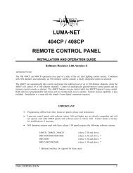
Components<br />
<strong>SW40</strong>-<strong>RH</strong> Half-Rack receivers include:<br />
• Power Supply<br />
• Dipole antennas (1 pair)<br />
• Rack Mount kit:<br />
Short rack ear<br />
Long rack ear<br />
Link bar to mount a second <strong>SW40</strong>-<strong>RH</strong> receiver<br />
8 rack screws<br />
4 rack mount screws<br />
• Extension cables and connectors for front-mounting antennas<br />
• 1/4 inch patch cable (not shown)<br />
• operating guide<br />
<strong>SW40</strong>-R modular receivers include:<br />
• Module Frame with 1, 2, 3 or 4 modules<br />
• Dipole antennas (1 pair)<br />
• Power Supply<br />
• Operating guide<br />
<strong>SW40</strong>-H Handheld transmitters include:<br />
• Microphone and transmitter<br />
• Mic holder<br />
• AA batteries (1 pair)<br />
<strong>SW40</strong>-T Beltpack transmitters include:<br />
• Beltpack transmitter<br />
• AA batteries (1 pair)<br />
<strong>SW40</strong>-T<br />
© 2010 Sabine, Inc.<br />
SWASS-EXT 3 SWT31L-TA4 SWT74W-OSB-TA4 SWT74W-ODB-TA4<br />
Optional:<br />
• Extention antennas.<br />
• lavalier microphone<br />
• single-ear microphone<br />
• double-ear microphone<br />
See www.Sabine.com for details.<br />
3 Sabine SWM4000 Smart Spectrum ® Wireless<br />
LIT-SWM4000-OG-EN-100205.indd
<strong>SW40</strong>-RF-Module Receiver Details<br />
Front Panel<br />
R1<br />
Power on/off<br />
<strong>SW40</strong>-RF<br />
POWER<br />
SCALE 1.000<br />
R1<br />
Module A Module B Module C Module D<br />
Module Front<br />
R2<br />
R5<br />
R6<br />
R9<br />
R10<br />
R12<br />
R2<br />
R3<br />
R4<br />
R5<br />
R6<br />
R7<br />
Volume (Gain)<br />
Squelch<br />
RF signal<br />
Active antenna<br />
I.R. sensor<br />
Group selection<br />
R8<br />
R9<br />
R10<br />
R11<br />
R12<br />
R13<br />
Channel number<br />
Lock all controls<br />
Set<br />
Menu<br />
Sync<br />
Audio signal<br />
VOL<br />
S.Q.<br />
A<br />
ANT<br />
B<br />
RF<br />
I.R.<br />
TRUE DIVERSITY<br />
RECEIVER UHF<br />
GROUP<br />
CHANNEL<br />
02 04<br />
<strong>SW40</strong>-RM<br />
SET<br />
MENU<br />
SYNC<br />
AF<br />
R3<br />
R4<br />
R7 R8 R11 R13<br />
Back Panel<br />
R14<br />
R15<br />
R16<br />
R15<br />
R16<br />
R15<br />
Antenna B<br />
XLR output jack for module D (balanced)<br />
1/4” jack output for module D (unbalanced)<br />
XLR output jack for module C (balanced)<br />
1/4” jack output for module C (unbalanced)<br />
XLR output jack for module B (balanced)<br />
R16<br />
R15<br />
R16<br />
R17<br />
R18<br />
R19<br />
1/4” jack output for module B (unbalanced)<br />
XLR output jack for module A (balanced)<br />
1/4” jack output for module A (unbalanced)<br />
Mixed output for all modules (unbalanced)<br />
PSU power jack<br />
Antenna A<br />
© 2010 Sabine, Inc.<br />
R14 R15 R16 R15 R16 R15 R16 R15 R16 R17 R18 R19<br />
Sabine SWM4000 Smart Spectrum ® Wireless<br />
4
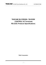
<strong>SW40</strong>-<strong>RH</strong> 1/2-Rack Receiver Details<br />
R1<br />
R2<br />
R4<br />
R6<br />
R10<br />
R11<br />
R12<br />
R13<br />
R20<br />
Power On/Off switch - Push up to turn on, push down to turn off.<br />
Volume control. The volume control dial should generally be left in the clockwise position.<br />
Turning the dial counter-clockwise decreases receiver output level.<br />
RF LED - Indicates strength of incoming RF signal.<br />
Smart option - Press to initiate IR connection between receiver and transmitter.<br />
Set switch - Press to select the currently displayed menu option.<br />
Menu switch - Press to scroll through menu options.<br />
Infrared (IR) port - Broadcasts IR signal to transmitter to synchronize frequencies..<br />
Audio LED - Indicates strength of incoming audio signal.<br />
LCD display<br />
<strong>SW40</strong>-<strong>RH</strong><br />
SET<br />
MENU<br />
R4<br />
R13 R20 R10 R11 R2 R12<br />
R6<br />
R1<br />
LCD display<br />
R5<br />
R7<br />
R8<br />
R9<br />
R21<br />
R22<br />
R23<br />
R24<br />
Antenna status<br />
Group selection<br />
Manual channel selection<br />
Lock/unlock receiver settings<br />
Transmitter Battery status<br />
Automatic frequency selection<br />
Display frequency<br />
Incompatable frequency<br />
R5<br />
R24<br />
INCOMPATIBLE<br />
R21 R22 R7<br />
R8<br />
R23<br />
R9<br />
© 2010 Sabine, Inc.<br />
R3<br />
R14<br />
R15<br />
R16<br />
R18<br />
R19<br />
R27<br />
Squelch<br />
Antenna jack B<br />
XLR output jack<br />
1/4 jack output jack<br />
AC adapter jack<br />
Antenna jack A<br />
Adapter cord tie-off<br />
<strong>SW40</strong>-<strong>RH</strong><br />
R14 R16 R15 R3<br />
R27 R18 R19<br />
5 Sabine SWM4000 Smart Spectrum ® Wireless<br />
LIT-SWM4000-OG-EN-100205.indd
Handheld Transmitter<br />
Controls<br />
To Open: Unscrew lower portion of microphone.<br />
Pull down as you continue to turn the housing.<br />
To Close: Turn the housing and push up until it<br />
meets the threads, then screw on.<br />
C<br />
D<br />
H5<br />
H6<br />
H1<br />
H2<br />
H3<br />
H4<br />
H5<br />
H6<br />
H7<br />
H8<br />
Select Button<br />
Up Button<br />
Down Button<br />
<strong>Pro</strong>grammable Control of External Switch<br />
Infrared Port<br />
Transmitter LCD Screen<br />
External Switch<br />
Transmitter controls and battery compartments<br />
A<br />
B<br />
E<br />
Transmitter LCD screen<br />
H8<br />
DTM2<br />
H7<br />
A<br />
B<br />
C<br />
D<br />
E<br />
Group Number<br />
Channel Number<br />
Antenna Indicator - Low output<br />
Antenna Indicator - High output<br />
Battery life Indicator<br />
H4<br />
H2<br />
H1<br />
H3<br />
Transmitter Controls<br />
<strong>Pro</strong>gramming the Handheld Transmitter<br />
SCALE 1.000<br />
A<br />
Group/Channel: Press the Select button to enter Edit Mode, and repeat until the<br />
GROUP indicator flashes. In this mode, the Up/Down buttons will adjust Group selection.<br />
Choose your group, then press the select button until the CHANNEL indicator<br />
flashes. In this mode, the Up/Down buttons will adjust Transmission Channel.<br />
C<br />
D<br />
RF Output: Press the Select button to enter Edit Mode, and repeat until the antenna<br />
indicators flashes. The small antenna symbol indicates low output (useful if there are<br />
many transmitters clustered together) and the large antenna symbol indicates high<br />
output (good for larger spaces). Press the up or down buttons to add or subtract the<br />
high-level output symbol.<br />
H4<br />
Internal Control of External Switch: The recessed transmitter controls include a<br />
3-position switch, which in turn determines how the transmitter’s external two-position<br />
switch behaves. From left-to-right, the 3 positions of the internal switch correspond<br />
to the following external switch operations. NOTE: The antenna symbol blinks when<br />
the transmitter is not muted.<br />
- ON-OFF: In the off position the transmitter is turned off. When you turn it on<br />
there is a short boot-up period before the mic turns on.<br />
- ON-MUTE: In the off position the audio is muted, but the transmitter is still<br />
on. Use this when you need the audio to come on instantly when turning on the<br />
microphone.<br />
- ON-ON: In both switch positions the mic is on. In essence you are disabling<br />
the external switch, and leaving the mic on at all times. This is useful if you are<br />
working with talent that might accidentally turn off the mic.<br />
© 2010 Sabine, Inc.<br />
Sabine SWM4000 Smart Spectrum ® Wireless<br />
E<br />
Battery Life Indicator: The battery symbol shows the battery level. Typical battery<br />
life is 8 hours.<br />
6
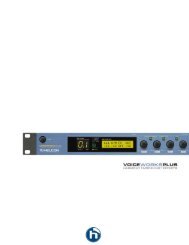
Beltpack Transmitter<br />
B1<br />
B2<br />
B3<br />
B4<br />
Controls<br />
B1<br />
B2<br />
B3<br />
B4<br />
B5<br />
B6<br />
B7<br />
B8<br />
B9<br />
Antenna (replaceable)<br />
LCD screen<br />
On-off/mute switch<br />
Press and hold to turn on or off. Press and release to mute or un-mute.<br />
Set switch<br />
Battery cover<br />
IR port - Receives infrared beam to synchronize frequencies.<br />
When using multiple systems, only one transmitter IR port should be exposed at a time.<br />
Gain adjustment switch<br />
Mute indicator - Red: mute on<br />
TA4-F microphone input jack<br />
B5<br />
<strong>SW40</strong>-T<br />
B6<br />
B7<br />
Wearing the Beltpack Transmitter<br />
Clip the transmitter to a belt until the belt is pressed<br />
against the base of the clip.<br />
B8<br />
B9<br />
Changing Batteries<br />
Expected life for an Alkaline battery is approximately 8 hours.<br />
Change batteries when the battery bar in LCD display is empty, as shown below:<br />
<strong>Pro</strong>gramming the Beltpack Transmitter<br />
1. With the power on, press and hold the set button until the GROUP and CHANNEL<br />
displays begin to alternate.<br />
2. To change the group setting, release the set button while GROUP is flashing. While<br />
GROUP is flashing, pressing set increases the group setting by one.<br />
3. Press power button to switch between GROUP and CHANNEL settings.<br />
Remember to press power and set button to confirm when the setting is completed.<br />
Press the power and set buttons simultaneously to lock or unlock the transmitter settings.<br />
When locked, the current settings cannot be changed manually.<br />
Indicates charge remaining in transmitter batteries.<br />
© 2010 Sabine, Inc.<br />
7 Sabine SWM4000 Smart Spectrum ® Wireless<br />
LIT-SWM4000-OG-EN-100205.indd
Operating Instructions<br />
Congratulations on purchasing your Sabine SWM4000 Series Wireless Microphone System. This system<br />
is specially designed to provide you with excellent audio quality, ease of use, and reliability.<br />
Frequency Bands The <strong>SW40</strong>00 series is available in several frequency bands to accommodate various<br />
local governmental regulations throughout the world. The frequency band of your system is represented<br />
by the numbers appended to the part number. For example, the <strong>SW40</strong>-RM3-U-915 operates in the 915<br />
MHz band while the <strong>SW40</strong>-RM3-E-860 operates in the 860 MHz band.<br />
The band recommended for the US and Canada, along with Central and South American is the 915 Mhz<br />
band. This band is immune to interference from analog and digital TV, mobile or smart phones, and most<br />
WIFI devices. It operates with up to 8 concurrent users in the same location.<br />
Contact your local distributor to determine the best band for your location outside of the Americas. Or, visit<br />
www.sabine.com for the most current information.<br />
Installing the <strong>SW40</strong>00 system in your sound system.<br />
Antennas. Antennas pick up the signal from the transmitters and transfers it to the receiver where it converted<br />
to an audio signal. A pair of SWAANT dipole antennas are included with your system. Antennas are<br />
like the “eyes” of the system. You will hear dropouts if the antennas cannot “see” the transmitter. Antennas<br />
cannot “see” through steel or concrete. If your antennas are mounted on the back of the receiver, rotate<br />
the receiver body around so that the antennas are in the line of sight of the transmitter.<br />
A receiver mounted in a rack must use the back-to-front cables and have the antennas mounted in the line<br />
of sight of the transmitter on the front of the rack. Also, dipole antennas should be orientated to the 11:00<br />
and 2:00 positions for the best reception.<br />
If the antennas are blocked or shadowed, you should replace the SWAANT antennas with Sabine’s<br />
SWASS-EXT-3 external antennas. Make sure you specify the frequency band of your system when<br />
you order.<br />
Audio Connections Your receiver has both a balanced XLR and unbalanced ¼-inch audio jacks on the<br />
back panel to connect the receiver to your mixer or powered speaker. Use the balanced jack whenever<br />
possible.<br />
Channel Selection Follow the steps on the next page to quickly find interference-free channels.<br />
Note: transmitting devices such as cellular phones and two-way radios may interfere with<br />
wireless audio transmissions. Keep your transmitters and receivers away from these and<br />
other potential sources of interference.<br />
© 2010 Sabine, Inc.<br />
Sabine SWM4000 Smart Spectrum ® Wireless<br />
8
<strong>SW40</strong>-T<br />
Setting up your Wireless Systems<br />
1. Plug the PSU power supply into the wall socket and receiver.<br />
2. (<strong>SW40</strong>-<strong>RH</strong>) Push the MENU button until the words Auto Select appear in the LCD. (<strong>SW40</strong>-RF) Push the MENU button until the words<br />
scan appear in the LCD.<br />
3. Push the SET button. The <strong>SW40</strong>-<strong>RH</strong> or SW-40-RF will set itself to a clear channel and display the channel on the receiver LCD.<br />
4. Turn on a transmitter (leave the other transmitters turned off). Aim the transmitter’s IR sensor about 8 inches from the receiver’s IR<br />
scanner and press the receiver’s S.O. (SYNC) button for several seconds while the receiver programs the transmitter. When the group<br />
and channel numbers on the transmitter matches the receiver, the system is ready to operate. When you are standing close, the RF<br />
LED ladder on the <strong>SW40</strong>-<strong>RH</strong> should be fully lit or, on the <strong>SW40</strong>-RF, the RF LED bar will be lit.<br />
Expose the IR port to the receiver (within 8 inches), press S.O. (SYNC)<br />
<strong>SW40</strong>-R<br />
<strong>SW40</strong>-<strong>RH</strong><br />
5. Speak, sing or play into the transmitter to adjust the volume control so that the A.F. LEDs generally light under normal performance<br />
conditions. The volume should be adjusted so that the top A.F. LED only lights momentarily with the loudest inputs. You will hear a<br />
harsh clipping sound if the top LED stays lit under normal levels.<br />
6. Adjusting the squelch. The squelch controls the maximum distance between the transmitter and receiver. It is set to maximum range<br />
at the factory and should be kept there in most cases.<br />
© 2010 Sabine, Inc.<br />
For Multiple Systems<br />
• Repeat steps 1 – 6 if you wish to add more systems. IMPORTANT: Make sure to keep the transmitters that have been set up<br />
turned on so that new receivers will know those channel are busy.<br />
• See Appendix A (pg.10) for manually selecting the frequencies of your system.<br />
• Be sure that only one transmitter’s IR port is exposed when setting up a system.<br />
9 Sabine SWM4000 Smart Spectrum ® Wireless<br />
LIT-SWM4000-OG-EN-100205.indd
Appendix A<br />
Manual <strong>Pro</strong>gramming<br />
R7<br />
R8<br />
R23<br />
R9<br />
R5<br />
R21<br />
R26<br />
<strong>All</strong>ows manual selection of a frequency group. Pressing SET increases the group number by one. When the correct<br />
frequency is displayed press S.O. (SYNC). For best results when operating multiple systems, set all systems to a single<br />
group; then set each system to a unique channel within that group.<br />
<strong>All</strong>ows manual selection of a frequency channel. Pressing SET increases the channel number by one. When the<br />
correct frequency is displayed press S.O. (SYNC).<br />
*<br />
Display the current frequency in MHz. Press again to display group and channel.<br />
Hold down the SET key and press MENU to lock or unlock the receiver. Locking prevent the current receiver settings<br />
from changing.<br />
Indicates RF activity. Only one antenna is active at any one time.<br />
Indicates a low transmitter battery charge.<br />
The INCOMPATIBLE warning indicates that the receiver and transmitter are set to incompatible frequency bands.<br />
Contact your retailer for assistance.<br />
Any option displayed on screen will generally time out after five seconds<br />
<strong>SW40</strong>-RF Module Front<br />
R2<br />
R5<br />
R6<br />
R9<br />
R10<br />
R12<br />
R2<br />
R3<br />
R4<br />
R5<br />
R6<br />
R7<br />
Volume (Gain)<br />
Squelch<br />
RF signal<br />
Active antenna<br />
I.R. sensor<br />
Group selection<br />
R8<br />
R9<br />
R10<br />
R11<br />
R12<br />
R13<br />
Channel number<br />
Lock all controls<br />
Set<br />
Menu<br />
Sync<br />
Audio signal<br />
VOL<br />
S.Q.<br />
A<br />
ANT<br />
B<br />
RF<br />
I.R.<br />
TRUE DIVERSITY<br />
RECEIVER UHF<br />
GROUP<br />
CHANNEL<br />
02 04<br />
<strong>SW40</strong>-RM<br />
SET<br />
MENU<br />
SYNC<br />
AF<br />
<strong>SW40</strong>-<strong>RH</strong> LCD display<br />
R5 Antenna status<br />
R7 Group selection<br />
R8 Manual channel selection<br />
R9 Lock/unlock receiver settings<br />
R21<br />
Transmitter Battery status<br />
R22 Automatic frequency selection<br />
R23 Display frequency<br />
R24<br />
Incompatable frequency<br />
R5<br />
R3<br />
R4<br />
R7 R8 R11 R13<br />
R24<br />
INCOMPATIBLE<br />
© 2010 Sabine, Inc.<br />
* Available only on the <strong>SW40</strong>-<strong>RH</strong><br />
Sabine SWM4000 Smart Spectrum ® Wireless<br />
R21 R22 R7<br />
R8<br />
R23<br />
10<br />
R9
Appendix B<br />
Frequencies and Groups<br />
FREQUENCY BAND SELECTION<br />
Most countries closely regulate radio frequency devices to limit RF (radio frequency) interference. Many countries are in<br />
the process of changing their regulations in order to accomodate requirements for DTV braodcasts and smart phones.<br />
SWM4000 systems are available in several frequency ranges. Contact your local retailer to determine the bands that<br />
are suitable in your area. Sabine is making new frequency bands available as the regulations evolve. The most current<br />
information can be found at www.Sabine.com.<br />
The following bands are available at the time this manual was printed:<br />
902-928 Mhz - For the Americas, Australia and New Zealand (These frequencies are expected to remain license free and<br />
relatively free of interference for the foreseable future.)<br />
790-819 MHz - For China<br />
790-865 MHz - for The Pacific Rim and some European countries.<br />
850-865 MHz - Some European countries.<br />
SWM4000 systems typically provide predefined frequency groups and channels. <strong>All</strong> microphones in a system should be<br />
set individual channels within a sinlge group to reduce the chance of interference. DO NOT SET TWO TRANSMITTERS<br />
TO THE SAME GROUP AND CHANNEL.<br />
Up to 8 individual transmitter/receiver systems may be used simultaniously in the same venue. It is possible to operate<br />
up to 20 systems simultaneously.<br />
Appendix C<br />
Rack-Mounting <strong>SW40</strong>-<strong>RH</strong> Receivers<br />
© 2010 Sabine, Inc.<br />
11 Sabine SWM4000 Smart Spectrum ® Wireless<br />
LIT-SWM4000-OG-EN-100205.indd
Appendix D<br />
© 2010 Sabine, Inc.<br />
Sabine SWM4000 Smart Spectrum ® Wireless<br />
12
Appendix E<br />
Specifications<br />
<strong>SW40</strong> Receiver<br />
Operating Range Under Typical Conditions<br />
100m (300 ft)<br />
Note: actual range depends on RF signal absorption,<br />
reflection, and interference<br />
Audio Frequency Response (+/- 2 dB)<br />
Maximum: 20 kHz<br />
Minimum: 50 Hz<br />
(Overall system frequency depends on microphone element.)<br />
Total Harmonic Distortion (ref. +/- 30 kHz deviation, 400Hz tone)<br />
0.5%, typical<br />
Dynamic Range<br />
>100 dB A-weighted<br />
Operating Temperature Range<br />
-18ºC (0~F) to +57ºC (+135ºF)<br />
Note: battery characteristics may limit this range<br />
Dimensions<br />
205 mmH x 160mmW x 39 mmD<br />
Weight<br />
960 g<br />
Housing<br />
Galvanized steel<br />
Audio Output Level(ref.+/- 30kHz deviation<br />
with 400Hz tone)<br />
XLR connector (into 600 Q load): -30dBV<br />
1/4 inch connector (into 3000 Q Ioad):-9dBV<br />
Output Impedance<br />
XLR connector: 200<br />
1/4 inch connector: 1k<br />
XLR output<br />
Impedance balanced<br />
Pin 1: Ground (cable shield)<br />
Pin 2: Audio<br />
Pin 3: No Audio<br />
Sensitivity<br />
-105 dBm for 12 dB SINAD, typical<br />
Image Rejection<br />
>70 dB, typical<br />
Power Requirements<br />
22V dc at 400mA, supplied by external<br />
power supply<br />
<strong>SW40</strong>-H Handheld Transmitter<br />
RF Transmitter Output<br />
30 mW maximum (dependent on applicable<br />
country regulations)<br />
Dimensions (including EM-l1S cartridge)<br />
270 mm x 52 mm dia.<br />
Weight<br />
250 g without batteries<br />
Housing<br />
Molded ABS handle and battery cup<br />
Power Requirements<br />
2 “AA” size alkaline or rechargeable batteries<br />
Battery Life<br />
>8 hours (alkaline)<br />
<strong>SW40</strong>-T Beltpack Transmitter<br />
Gain Adjustment Range<br />
30 dB<br />
Input Impedance<br />
500 K<br />
RF Transmitter Output<br />
30 mW maximum (dependent on applicable country<br />
regulations)<br />
Dimensions<br />
85 mm H x 70 mm W x 20 min D<br />
Weight<br />
97 g without batteries<br />
Housing<br />
Molded ABS case<br />
Power Requirements<br />
2”AA’ size alkaline or rechargeable batteries<br />
Battery Life<br />
>8 hours (alkaline)<br />
© 2010 Sabine, Inc.<br />
13 Sabine SWM4000 Smart Spectrum ® Wireless<br />
LIT-SWM4000-OG-EN-100205.indd
NOTES:<br />
© 2010 Sabine, Inc.<br />
Sabine SWM4000 Smart Spectrum ® Wireless<br />
14
NOTES:<br />
© 2010 Sabine, Inc.<br />
15 Sabine SWM4000 Smart Spectrum ® Wireless<br />
LIT-SWM4000-OG-EN-100205.indd
03/01/2010<br />
WIRELESS SYSTEMS<br />
Sabine, Inc.<br />
13301 NW US Highway 441<br />
Alachua, Florida 32615-8544 USA<br />
Phone: (386) 418-2000<br />
Fax: (386) 418-2001<br />
www.Sabine.com