Differential Protection for Power Transformers With Non-Standard ...
Differential Protection for Power Transformers With Non-Standard ...
Differential Protection for Power Transformers With Non-Standard ...

You also want an ePaper? Increase the reach of your titles
YUMPU automatically turns print PDFs into web optimized ePapers that Google loves.
equals 313.7 Amps, the selected CT primary should not be less<br />
than 400 A. Another factor <strong>for</strong> CT selection is the capability of<br />
the CT to replicate high fault currents without significant<br />
saturation. Hence the mismatch between the currents measured<br />
by the relay and the currents needed <strong>for</strong> providing the<br />
differential protection is evident. To make it simple, the user<br />
selects a magnitude reference winding with meaning of<br />
winding phase-phase voltage and winding CT primary, and the<br />
algorithm computes the magnitude compensation coefficients,<br />
by which the non-reference winding currents are scaled. If<br />
winding 1 is selected as a reference winding, the magnitude<br />
compensation coefficient <strong>for</strong> winding 2 would be:<br />
M 1 - magnitude reference winding<br />
1 ( w1)<br />
=<br />
kV ( w2)*<br />
CTprim<br />
( w 2)<br />
M2(<br />
w 2) = (2)<br />
kV ( w1)*<br />
CTprim<br />
( w1)<br />
For the above example, with winding 1 CT (500:5), and<br />
winding 2 CT (2000:5), the currents from winding 2 CTs<br />
would be multiplied by magnitude compensation factor of 0.8.<br />
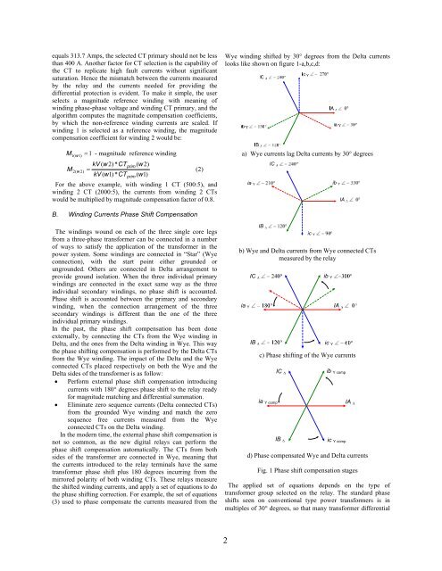
Wye winding shifted by 30° degrees from the Delta currents<br />
looks like shown on figure 1-a,b,c,d:<br />
a) Wye currents lag Delta currents by 30° degrees<br />
ia Y<br />
IC<br />
ib Y<br />
IA<br />
B. Winding Currents Phase Shift Compensation<br />
The windings wound on each of the three single core legs<br />
from a three-phase trans<strong>for</strong>mer can be connected in a number<br />
of ways to satisfy the application of the trans<strong>for</strong>mer in the<br />
power system. Some windings are connected in “Star” (Wye<br />
connection), with the start point either grounded or<br />
ungrounded. Others are connected in Delta arrangement to<br />
provide ground isolation. When the three individual primary<br />
windings are connected in the exact same way as the three<br />
individual secondary windings, no phase shift is accounted.<br />
Phase shift is accounted between the primary and secondary<br />
winding, when the connection arrangement of the three<br />
secondary windings is different than the one of the three<br />
individual primary windings.<br />
In the past, the phase shift compensation has been done<br />
externally, by connecting the CTs from the Wye winding in<br />
Delta, and the ones from the Delta winding in Wye. This way<br />
the phase shifting compensation is per<strong>for</strong>med by the Delta CTs<br />
from the Wye winding. The impact of the Delta and the Wye<br />
connected CTs placed respectively on both the Wye and the<br />
Delta sides of the trans<strong>for</strong>mer is as follow:<br />
• Per<strong>for</strong>m external phase shift compensation introducing<br />
currents with 180° degrees phase shift to the relay ready<br />
<strong>for</strong> magnitude matching and differential summation.<br />
• Eliminate zero sequence currents (Delta connected CTs)<br />
from the grounded Wye winding and match the zero<br />
sequence free currents measured from the Wye<br />
connected CTs on the Delta winding.<br />
In the modern time, the external phase shift compensation is<br />
not so common, as the new digital relays can per<strong>for</strong>m the<br />
phase shift compensation automatically. The CTs from both<br />
sides of the trans<strong>for</strong>mer are connected in Wye, meaning that<br />
the currents introduced to the relay terminals have the same<br />
trans<strong>for</strong>mer phase shift plus 180 degrees incurring from the<br />
mirrored polarity of both winding CTs. These relays measure<br />
the shifted winding currents, and apply a set of equations to do<br />
the phase shifting correction. For example, the set of equations<br />
(3) used to phase compensate the currents measured from the<br />
b) Wye and Delta currents from Wye connected CTs<br />
measured by the relay<br />
ia Y<br />
IC<br />
IB<br />
IB<br />
c) Phase shifting of the Wye currents<br />
ia Y comp<br />
IC Δ<br />
IB Δ<br />
ib Y comp<br />
ic Y comp<br />
IA Δ<br />
d) Phase compensated Wye and Delta currents<br />
Fig. 1 Phase shift compensation stages<br />
The applied set of equations depends on the type of<br />
trans<strong>for</strong>mer group selected on the relay. The standard phase<br />
shifts seen on conventional type power trans<strong>for</strong>mers is in<br />
multiples of 30° degrees, so that many trans<strong>for</strong>mer differential<br />
ic Y<br />
ib Y<br />
IA<br />
ic Y<br />
2