Differential Protection for Power Transformers With Non-Standard ...
Differential Protection for Power Transformers With Non-Standard ...
Differential Protection for Power Transformers With Non-Standard ...

Create successful ePaper yourself
Turn your PDF publications into a flip-book with our unique Google optimized e-Paper software.
protection relays provide a pre-set table <strong>for</strong> selection of the<br />
desired trans<strong>for</strong>mer type. The table contains combinations of<br />
Wye, Delta and Zig-Zag windings <strong>for</strong> two and three winding<br />
trans<strong>for</strong>mers with standard phase shifts that are in multiples of<br />
30° degrees angles. As seen further, this approach of defining<br />
the trans<strong>for</strong>mer phase shift to the trans<strong>for</strong>mer protective relay<br />
is not very sufficient <strong>for</strong> some trans<strong>for</strong>mers with non-standard<br />
phase shifts.<br />
iaΥ<br />
− ibΥ<br />
iaΥ<br />
comp<br />
=<br />
3<br />
ibΥ<br />
− icΥ<br />
ibΥ<br />
comp<br />
=<br />
(3)<br />
3<br />
icΥ<br />
comp<br />
ic<br />
=<br />
Υ<br />
− ia<br />
3<br />
Υ<br />
V L<br />
Θ<br />
X<br />
sides<br />
SOURCE<br />
- per unit voltage of the Load side<br />
- phase angle difference between VS<br />
and V L<br />
- per unit reactance between the Source and Load<br />
SERIES<br />
UNIT<br />
LOAD<br />
III.<br />
TRANSFORMERS WITH NON-STANDARD<br />
PHASE SHIFTS<br />
EXCITING<br />
UNIT<br />
Depending on the core-winding construction, some power<br />
trans<strong>for</strong>mers do not introduce a standard phase shift of 30°, or<br />
multiples of 30° degrees. Employing differential protection <strong>for</strong><br />
such trans<strong>for</strong>mers is not straight <strong>for</strong>ward, and requires more<br />
analysis. The main concerns would be to define the following:<br />
• zone of protection, and places of current trans<strong>for</strong>mers<br />
• winding currents and phase shifts<br />
• special CTs - relay terminals connections<br />
• selection of protective relay that can be successfully<br />
applied without the need of connecting any costly<br />
auxiliary CTs or equipment in general<br />
A. Phase Shifting Trans<strong>for</strong>mers<br />
The Phase Shifting Trans<strong>for</strong>mers (PSTs) are used to control<br />
the active and reactive power flow through a line by varying<br />
the phase angle between its source and load voltages. The PST<br />
controls the power by inserting regulated quadrature voltage in<br />
series with the line to neutral voltage of the series winding<br />
(Fig.2). There are different types PSTs, depending on their<br />
application and construction: with or without Load Tap<br />
Changer(LTC), PSTs with Delta/Wye or Wye/Wye exciting<br />
unit configuration, with or without voltage regulating winding,<br />
or hexagonal designed. They also differ by power and voltage<br />
ratings, and provide different ranges of phase angle regulation.<br />
A conventional type PST (Fig.2) consists of two units: Series<br />
Unit with secondary winding connected in Delta, and an<br />
Exciting Unit of Wye connected primary and secondary<br />
windings with grounded neutrals. The Load Tap Changer is<br />
located on the secondary Wye winding from the Exciting unit,<br />
and is used to control the quadrature voltage magnitude used to<br />
shift the angle of the Load side voltage with respect to the<br />
Source side voltage. The power flow between the Source and<br />
Load sides of the PST can be approximated by the following<br />
equation:<br />
VS<br />
* VL<br />
*sin Θ<br />
P =<br />
(4)<br />
X<br />
where,<br />
P - real power flow per unit<br />
V - per unit voltage of the Source side<br />
S<br />
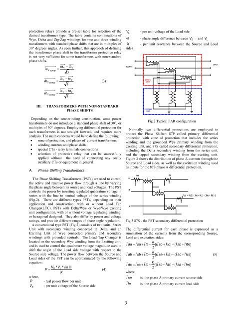
Fig.2 Typical PAR configuration<br />
Normally two differential protections are employed to<br />
protect the Phase Shifter: 87P called primary differential<br />
protection with zone of protection that includes the series<br />
winding and the grounded Wye primary winding from the<br />
exciting unit, and 87S called secondary differential protection,<br />
including the Delta secondary winding from the series unit,<br />
and the tapped secondary winding from the exciting unit.<br />
Figure 3 shows the distribution of phase A currents through the<br />
Source and Load sides, as well as the excitation winding used<br />
as inputs <strong>for</strong> the 87S phase A differential protection.<br />
A<br />
B<br />
C<br />
Isa<br />
Ila<br />
I'ea = k/2 [ ( Isc + Ilc ) - ( Isb + Ilb ) ]<br />
Fig.3 87S - the PST secondary differential protection<br />
The differential current <strong>for</strong> each phase is expressed as a<br />
summation of the currents from the corresponding Source,<br />
Load and excitation sides:<br />
v v v k v v v v<br />
I da = I sa + I la + [( I sc + I lc)<br />
− ( I sb + I lb)]<br />
2<br />
v v v k v v v v<br />
I db = I sb + I lb + [( I sa + I la)<br />
− ( I sc + I lc)]<br />
(5)<br />
2<br />
v v v k v v v v<br />
I dc = I sc + I lc + [( I sb + I lb)<br />
− ( I sa + I la)]<br />
2<br />
where,<br />
I r<br />
sa<br />
I r<br />
la<br />
is the phase A primary current source side<br />
is the phase A primary current load side<br />
3