Differential Protection for Power Transformers With Non-Standard ...
Differential Protection for Power Transformers With Non-Standard ...
Differential Protection for Power Transformers With Non-Standard ...

You also want an ePaper? Increase the reach of your titles
YUMPU automatically turns print PDFs into web optimized ePapers that Google loves.
v k v v v v<br />
I ' ea = [( I sc + I lc)<br />
− ( I sb + I lb)]<br />
is the phase A exciting<br />
2<br />
current<br />
k is the series unit turns ratio<br />
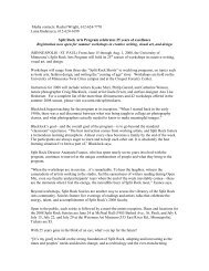
Working out with the Source, Load, and exciting unit current<br />
per phase, one can arrive to the conclusion that the angle (Fig.<br />
4) between the current (summation of the source and load<br />
currents), and the exciting unit current is 90° degrees. This<br />
angle has to be reflected in the trans<strong>for</strong>mer setup to assure<br />
correct phase shift compensation.<br />
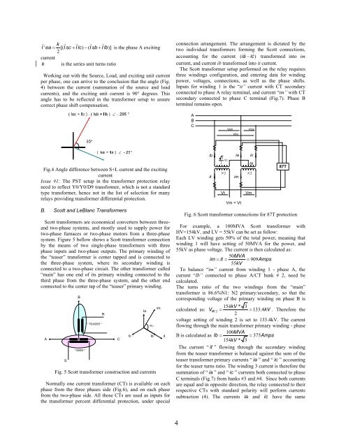
connection arrangement. The arrangement is dictated by the<br />
two individual trans<strong>for</strong>mers <strong>for</strong>ming the Scott connections,<br />
v v<br />
accounting <strong>for</strong> the current ( ia − ic)<br />
trans<strong>for</strong>med into im<br />
current, and current ib trans<strong>for</strong>med into it current.<br />
The Scott trans<strong>for</strong>mer setup per<strong>for</strong>med on the relay requires<br />
three windings configuration, and entering data <strong>for</strong> winding<br />
power, voltages, connections, as well as the phase shifts.<br />
Inputs <strong>for</strong> winding 1 is the “it” current with CT secondary<br />
connected to phase A relay terminal, and current “im” with CT<br />
secondary connected to phase C terminal (Fig.7). Phase B<br />
terminal remains open.<br />
A<br />
B<br />
C<br />
Vab<br />
Vbc<br />
Vca<br />
Fig.4 Angle difference between S+L current and the exciting<br />
current<br />
Issue #1: The PST setup in the trans<strong>for</strong>mer protection relay<br />
need to reflect Y0/Y0/D9 trans<strong>for</strong>mer, which is not a standard<br />
type trans<strong>for</strong>mer, hence not in the list of selection <strong>for</strong> many<br />
relays providing trans<strong>for</strong>mer differential protection.<br />
B. Scott and LeBlanc Trans<strong>for</strong>mers<br />
Scott trans<strong>for</strong>mers are economical converters between threeand<br />
two-phase systems, and mostly used to supply power <strong>for</strong><br />
two-phase furnaces or two-phase motors from a three-phase<br />
system. Figure 5 bellow shows a Scott trans<strong>for</strong>mer connection<br />
by the means of two single-phase trans<strong>for</strong>mers with three<br />
phase inputs and two-phase outputs. The primary winding of<br />
the “teaser” trans<strong>for</strong>mer is center tapped and is connected to<br />
the three-phase system, where its secondary winding is<br />
connected to a two-phase circuit. The other trans<strong>for</strong>mer called<br />
“main” has one end of its primary winding connected to the<br />
third phase from the three-phase system, and the other end<br />
connected to the center tap of the “teaser” primary winding.<br />
A<br />
S<br />
B<br />
" MAIN "<br />
" TEASER "<br />
R<br />
Fig. 5 Scott trans<strong>for</strong>mer construction and currents<br />
Normally one current trans<strong>for</strong>mer (CT) is available on each<br />
phase from the three phases side (Fig.6), and on each phase<br />
from the two-phase side. All those CTs are used as inputs <strong>for</strong><br />
the trans<strong>for</strong>mer percent differential protection, under special<br />
C<br />
Ic<br />
Ia<br />
90∠<br />
Ib<br />
im<br />
it<br />
ib ia ic<br />
3 N 1<br />
2<br />
N1<br />
N 2<br />
N2<br />
it<br />
im<br />
Vt<br />
Vm = Vt<br />
Vm<br />
87T<br />
Fig. 6 Scott trans<strong>for</strong>mer connections <strong>for</strong> 87T protection<br />
For example, a 100MVA Scott trans<strong>for</strong>mer with<br />
HV=154kV, and LV = 55kV can be set as follow:<br />
Each LV winding gets 50% of the total power, meaning that<br />
winding 1 will have setting of 50MVA <strong>for</strong> the power, and<br />
55kV as phase voltage. The current is then calculated as:<br />
50MVA<br />
im = it = = 909Amps<br />
55kV<br />
To balance “im” current from winding 1 - phase A, the<br />
current “Ib” connected to phase A/CT bank # 2, need be<br />
calculated.<br />
The turns ratio of the two windings from the “main”<br />
trans<strong>for</strong>mer is 86.6%N1: N2 primary/secondary, so that the<br />
corresponding voltage of the primary winding on phase B is<br />
154kV<br />
* 3<br />
calculated as: V W 2 = = 133. 4kV<br />
. There<strong>for</strong>e the<br />
2<br />
voltage setting of winding 2 is set to 133.4kV. The current<br />
flowing through the main trans<strong>for</strong>mer primary winding - phase<br />
100MVA<br />
B is calculated as Ib =<br />
= 375Amps<br />
154kV<br />
* 3<br />
The current “ it ” flowing through the secondary winding<br />
from the teaser trans<strong>for</strong>mer is balanced against the sum of the<br />
teaser trans<strong>for</strong>mer primary currents “ ia ” and “ ic ” accounting<br />
<strong>for</strong> the teaser turns ratio. The winding 3 current is there<strong>for</strong>e the<br />
summation of “ ia ” and “ ic ” currents both connected to phase<br />
C terminals (Fig.7) from banks #3 and #4. Since both currents<br />
are equal and in opposite direction, the relay connected to their<br />
respective CTs with standard polarity will per<strong>for</strong>m currents<br />
subtraction (4). The currents ia and ic have the same<br />
4