Differential Protection for Power Transformers With Non-Standard ...
Differential Protection for Power Transformers With Non-Standard ...
Differential Protection for Power Transformers With Non-Standard ...

You also want an ePaper? Increase the reach of your titles
YUMPU automatically turns print PDFs into web optimized ePapers that Google loves.
-300° and -360° deg sector<br />
Applying the <strong>for</strong>mula (6), the compensation angle equals -<br />
352.5 degrees.<br />
The Wye currents ia Y , ib Y , and ic Y are expressed using the<br />
reference winding currents.<br />
Y<br />
AA<br />
o<br />
ia ∠ Θ = k . Ia∠0<br />
+ k . Ib∠ −120<br />
+ k . Ic∠<br />
− 240<br />
Y<br />
BA<br />
o<br />
AB<br />
ib ∠ Θ = k . Ia∠0<br />
+ k . Ib∠ −120<br />
+ k . Ic∠<br />
− 240<br />
Y<br />
CA<br />
o<br />
BB<br />
ic ∠ Θ = k . Ia∠0<br />
+ k . Ib∠ −120<br />
+ k . Ic∠<br />
− 240<br />
CB<br />
Working <strong>for</strong> ia Y current, the coefficients corresponding to PCA<br />
of -352.5° deg angle will be as follow:<br />
1 3 1 3<br />
cosΘ<br />
+ j sin Θ = k AA + k AB.(<br />
− − j.<br />
) + k AC .( − + j.<br />
)<br />
2 2 2 2<br />
where,<br />
1 1<br />
cosΘ = k AA − k AB − k AC<br />
2 2<br />
(7)<br />
3 3<br />
sin Θ = − k AB + k AC<br />
2 2<br />
Solving (6) <strong>for</strong> k AA , k AB , and k AC , and compensation angle<br />
falling into the (-300° ÷ -360°) sector, the phase shift<br />
coefficients <strong>for</strong> Phase A current will be:<br />
k AA = cos Θ −<br />
1<br />
sin Θ<br />
3<br />
k AB = −<br />
2<br />
sin Θ<br />
3<br />
(8a)<br />
k AC = 0<br />
Correspondingly, the phase shift coefficients <strong>for</strong> Phase B will<br />
be:<br />
kBA<br />
= 0<br />
kBB<br />
= cos Θ −<br />
1<br />
sin Θ<br />
(8b)<br />
3<br />
kBC<br />
= −<br />
2<br />
sin Θ<br />
3<br />
and the ones <strong>for</strong> phase C will be:<br />
kCA<br />
= −<br />
2<br />
sin Θ<br />
3<br />
k = 0<br />
(8c)<br />
CB<br />
1<br />
kCC<br />
= cos Θ − sin Θ<br />
3<br />
Applying the equations <strong>for</strong> phase A current (ia Y ∠-352.5°), we<br />
have the coefficients:<br />
o<br />
o<br />
o<br />
AC<br />
BC<br />
CC<br />
o<br />
o<br />
o<br />
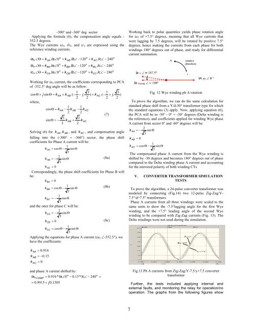
Working back to polar quantities yields phase rotation angle<br />
<strong>for</strong> ia Y of +7.5° degrees, meaning that all Wye currents that<br />
were lagging by 7.5 degrees, will be rotated by positive 7.5°<br />
degrees, hence making the currents from each phase <strong>for</strong> both<br />
windings 180° degrees out of phase, and ready <strong>for</strong> differential<br />
current summation.<br />
Fig. 12 Wye winding ph A rotation<br />
To prove the algorithm, we can do the same calculation <strong>for</strong><br />
standard phase shift from a Y/d-30° trans<strong>for</strong>mer type <strong>for</strong> which<br />
the standard equations (3) apply. Now, applying equation (6),<br />
the PCA will be to -30° - 0° = -30° degrees (Delta winding is<br />
the reference), and coefficients applied <strong>for</strong> winding Wye phase<br />
A current from sector 0° and -60° degrees will be:<br />
2<br />
k AA = − sin Θ<br />
3<br />
k = 0<br />
AB<br />
1<br />
k AC = cos Θ − sin Θ<br />
3<br />
The compensated phase A current from the Wye winding is<br />
shifted by -30 degrees and becomes 180° degrees out of phase<br />
compared to the Delta winding phase A current and accounting<br />
<strong>for</strong> the mirrored polarity of both winding CTs<br />
V. CONVERTER TRANSFORMER SIMULATION<br />
TESTS<br />
To prove the algorithm, a 24-pulse converter trans<strong>for</strong>mer was<br />
modeled by connecting (Fig.14) two 12-pulse Zig-Zag/Y-<br />
7.5°/d+7.5° trans<strong>for</strong>mers.<br />
Phase A currents from all three windings were scaled to the<br />
same units to show the -7.5°lagging angle <strong>for</strong> the first Wye<br />
winding, and the +7.5° leading angle of the second Wye<br />
winding to be compared with Zig-Zag currents (Fig. 13). The<br />
Delta windings were not used during the simulation.<br />
k<br />
k<br />
k<br />
AA<br />
AB<br />
AC<br />
= 0.916<br />
= −0.15<br />
= 0<br />
and phase A current shifted by:<br />
ia<br />
Y COMP<br />
= 0.916* Ia∠0<br />
= 0.9915 + j0.1305<br />
o<br />
− 0.15* Ic∠ − 240<br />
o<br />
=<br />
Fig.13 Ph A currents from Zig-Zag/Y-7.5/y+7.5 converter<br />
trans<strong>for</strong>mer<br />
Further, the tests included applying internal and<br />
external faults, and monitoring the relay <strong>for</strong> operation/no<br />
operation. The graphs from the following figures show<br />
7