Microstrip Patch Antennas for Broadband Indoor Wireless Systems ...
Microstrip Patch Antennas for Broadband Indoor Wireless Systems ...
Microstrip Patch Antennas for Broadband Indoor Wireless Systems ...

You also want an ePaper? Increase the reach of your titles
YUMPU automatically turns print PDFs into web optimized ePapers that Google loves.
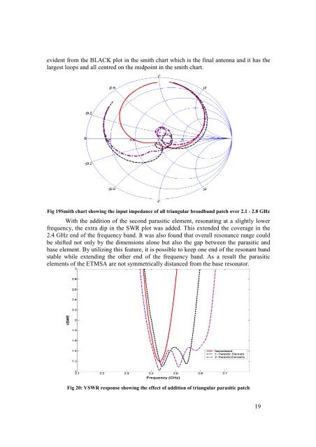
evident from the BLACK plot in the smith chart which is the final antenna and it has the<br />
largest loops and all centred on the midpoint in the smith chart.<br />
Fig 19Smith chart showing the input impedance of all triangular broadband patch over 2.1 - 2.8 GHz<br />
With the addition of the second parasitic element, resonating at a slightly lower<br />
frequency, the extra dip in the SWR plot was added. This extended the coverage in the<br />
2.4 GHz end of the frequency band. It was also found that overall resonance range could<br />
be shifted not only by the dimensions alone but also the gap between the parasitic and<br />
base element. By utilizing this feature, it is possible to keep one end of the resonant band<br />
stable while extending the other end of the frequency band. As a result the parasitic<br />
elements of the ETMSA are not symmetrically distanced from the base resonator.<br />
Fig 20: VSWR response showing the effect of addition of triangular parasitic patch<br />
19