Microstrip Patch Antennas for Broadband Indoor Wireless Systems ...
Microstrip Patch Antennas for Broadband Indoor Wireless Systems ...
Microstrip Patch Antennas for Broadband Indoor Wireless Systems ...

You also want an ePaper? Increase the reach of your titles
YUMPU automatically turns print PDFs into web optimized ePapers that Google loves.
8.0 ISSUES TO CONSIDER FOR FUTURE RESEARCH<br />
A major hurdle the project suffered from was the inability of the new PCB milling<br />
machine to produce high frequency PCB boards. When removing the extra copper from<br />
the substrate, the machine removed significant amount of substrate, resulting in reduced<br />
height and also creating ripples along the substrate plane. As a result the calculated ε r<br />
was incorrect, ensuing incorrect antenna dimensions and changing antenna behavior. The<br />
milling machine also had a turn around period of a few weeks. Due to these facts, we<br />
were <strong>for</strong>ced to investigate other viable options and ultimately the use of adhesive copper<br />
tapes. The use of copper tapes meant there was no turn around period and allowed us to<br />
resize the dimensions quickly and test the difference. This led to quick impedance<br />
matching within a small period of time. Consequently broadband antennas require a good<br />
impedance match to per<strong>for</strong>m and require a process where each result builds upon the last<br />
in order to achieve an adequate match.<br />
In deciding to use the copper tape, the active decision was made to trade off<br />
accuracy <strong>for</strong> time. It is imperative to be extremely accurate when incising the dimensions<br />
from the copper tape, because a difference of 0.5mm can shift the resonating frequency of<br />
the patch. A decision was made early on, to produce two boards <strong>for</strong> each design, to make<br />
sure that the results can be repeatable. It is important to account <strong>for</strong> all the feeder losses<br />
in order to obtain truly representative results. Individual feeder looses were measured<br />
using the test receiver and a step attenuator. Where a known attenuation is placed in<br />
series with the signal generator and connected to the test receiver. Since the generator<br />
output is known along with the attenuation, it is possible to account <strong>for</strong> the extra losses<br />
due to the feeder and the insertion loss introduced by the signal generator.<br />
For future research and project, it is strongly recommended that a substrate with<br />
stable ε r be used. According to Rogers Corporation datasheets the tolerance of G10<br />
(FR4) is in the ±0.2 range [10], which indicates a large error limit in terms of radio<br />
frequency design. The G10 fibreglass substrate is barely adequate <strong>for</strong> its use in the 2.45 –<br />
2.5 GHz frequency range. For use of frequencies any higher, it would require a substrate<br />
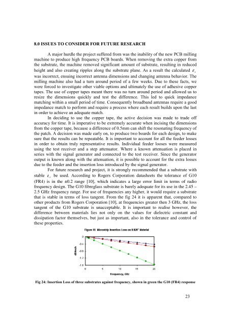
that is stable in terms of loss tangent. From the fig 24 it is apparent that, compared to<br />
other products from Rogers Corporation [10], at frequencies greater then 3 GHz, the loss<br />
tangent of the G10 substrate is unacceptable. It is important to realise however, the<br />
difference between materials lies not only on the values <strong>for</strong> dielectric constant and<br />
dissipation factor themselves, but just as important, also in the tolerance and control of<br />
these properties.<br />
Fig 24: Insertion Loss of three substrates against frequency, shown in green the G10 (FR4) response<br />
23