FB00FCY - Teledyne Relays
FB00FCY - Teledyne Relays
FB00FCY - Teledyne Relays

Create successful ePaper yourself
Turn your PDF publications into a flip-book with our unique Google optimized e-Paper software.
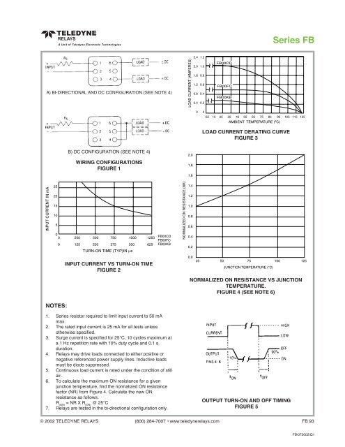
Series FB<br />
A) BI-DIRECTIONAL AND DC CONFIGURATION (SEE NOTE 4)<br />
LOAD CURRENT DERATING CURVE<br />
FIGURE 3<br />
B) DC CONFIGURATION (SEE NOTE 4)<br />
WIRING CONFIGURATIONS<br />
FIGURE 1<br />
INPUT CURRENT VS TURN-ON TIME<br />
FIGURE 2<br />
NORMALIZED ON RESISTANCE VS JUNCTION<br />
TEMPERATURE.<br />
FIGURE 4 (SEE NOTE 6)<br />
NOTES:<br />
1. Series resistor required to limit input current to 50 mA<br />
max.<br />
2. The rated input current is 25 mA for all tests unless<br />
otherwise specified.<br />
3. Surge current is specified for 25°C, 10 cycles maximum at<br />
a 1 Hz repetition rate with 10% duty cycle and 0.1 s.<br />
duration.<br />
4. <strong>Relays</strong> may drive loads connected to either positive or<br />
negative referenced power supply lines. Inductive loads<br />
must be diode suppressed.<br />
5. Continuous load current is rated under the condition of still<br />
air.<br />
6. To calculate the maximum ON resistance for a given<br />
junction temperature, find the normalized ON resistance<br />
factor (NR) from Figure 4. Calculate the new ON<br />
resistance as follows:<br />
R (ON)<br />
= NR X R (ON)<br />
@ 25°C<br />
7. <strong>Relays</strong> are tested in the bi-directional configuration only.<br />
OUTPUT TURN-ON AND OFF TIMING<br />
FIGURE 5<br />
© 2002 TELEDYNE RELAYS (800) 284-7007 • www.teledynerelays.com FB 93<br />
FB\072002\Q1