Incremental Encoders GEL 207, 208, 209, 219 T T - Motor ...
Incremental Encoders GEL 207, 208, 209, 219 T T - Motor ...
Incremental Encoders GEL 207, 208, 209, 219 T T - Motor ...

Create successful ePaper yourself
Turn your PDF publications into a flip-book with our unique Google optimized e-Paper software.
<strong>Incremental</strong> <strong>Encoders</strong><br />
<strong>GEL</strong> <strong>207</strong>, <strong>208</strong>, <strong>209</strong>, <strong>219</strong><br />
Magnetic measuring system<br />
Technical information Version 09.01<br />
T<br />
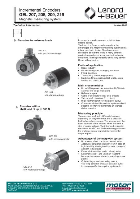
<strong>Encoders</strong> for extreme loads<br />
<strong>GEL</strong> <strong>207</strong><br />
with synchronous flange<br />
<strong>Incremental</strong> encoders convert rotations into<br />
electric signals.<br />
The Lenord + Bauer encoders combine the<br />
advantages of a magnetic measuring system and a<br />
robust mechanic design. They have proven<br />
successful all over the world in many different<br />
applications and even under roughest industrial<br />
conditions. Their high reliability and a long service<br />
life go without saying.<br />
Fields of application<br />
• Heavy industry<br />
• Paper-making and packaging machines<br />
• Filling machines<br />
• Transporting and storing systems<br />
• Machines for processing steel, wood, stone,<br />
textiles and plastic, etc.<br />
T<br />
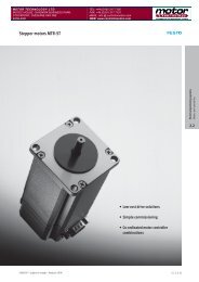
<strong>Encoders</strong> with a<br />
shaft load of up to 500 N<br />
<strong>GEL</strong> <strong>219</strong><br />
with rectangular flange<br />
<strong>GEL</strong> <strong>208</strong><br />
with clamping flange<br />
<strong>GEL</strong> <strong>209</strong><br />
with bearing pedestal<br />
Main characteristics<br />
• Up to 5,000 pulses per revolution (20,000 with<br />
external four-edge evaluation)<br />
• Reference signal<br />
• Cable or connector outlet, axial or radial<br />
• Various shaft diameters, 6 … 16 mm<br />
• High electromagnetic compatibility (EMC)<br />
• Our extremely flexible modular system makes it<br />
possible to offer our customers an express<br />
delivery service<br />
Measuring principle<br />
The encoders work with differential sensors<br />
depending on magnetic fields and a precision<br />
toothed wheel as measure. The sensors scan the<br />
tooth structure of the toothed wheel and emit a<br />
sine or cosine voltage. The integrated evaluation<br />
electronics in ASIC and SMD technology converts<br />
the analogue sensor signals into incremental<br />
output signals.<br />
Advantages of the magnetic system<br />
• No adverse effect due to condensed water<br />
• Absolute operational reliability even in case of<br />
high humidity (dewing) and frequent change of<br />
ambient temperature<br />
• Extremely insensitive to dirt, oil and water<br />
• Extremely shock- and vibration-resistant<br />
because the measure is not made of glass nor<br />
plastic<br />
• Outstanding operational safety over a<br />
very long period of time as it does not suffer<br />
from ageing effects as optical systems do<br />
MOTOR TECHNOLOGY LTD<br />
MOTEC HOUSE, CHADKIRK INDUSTRIAL ESTATE,<br />
ROMILEY, STOCKPORT, CHESHIRE SK6 3LE<br />
ENGLAND<br />
TELEPHONE: +44 (0)161 427 3641<br />
FAX: +44 (0)161 427 1306<br />
E-MAIL: sales@motec.co.uk<br />
WEB SITE: www.motec.co.uk
Output signals<br />
Signal pattern V, VN<br />
Two tracks with square-wave signals offset by 90°. On the<br />
third track N (option) a reference signal with defined<br />
length is output once per revolution.<br />
Signal pattern T, TN, U, UN, X, XN<br />
Both tracks and the reference signal (option) are<br />
additionally output as inverse signals.<br />
=<br />
8<br />
8 <br />
><br />
.<br />
JH= <br />
JH= <br />
F JE <br />
7 * 7 5<br />
8 8 ! 8 , + ! 8 , +<br />
Key<br />
U B<br />
= operating voltage<br />
U S<br />
= signal voltage<br />
a = 360° electrical<br />
b = 90° phase shift<br />
F = edge distance (for an output frequency of<br />
200 kHz the edge distance is F > 0.6 µ)<br />
Signal pattern = shown for clockwise rotation (view on top<br />
of the encoder shaft)<br />
Reference signals with other lengths upon request.<br />
Output level<br />
The signal patterns V, VN, X and XN have HTL level, the<br />
signal patterns T, TN, U and UN have TTL level (for the<br />
output voltage see electrical data).<br />
All outputs have a push-pull power amplifier and are<br />
short-circuit-proof. The peak output current for recharging<br />
the cable capacity is 100 mA.<br />
Technical data according to DIN 32878<br />
Description<br />
<strong>GEL</strong> <strong>207</strong>/<strong>208</strong>/<strong>209</strong>/<strong>219</strong><br />
)<br />
m easuring step from ... to<br />
)<br />
p ulse number per revolution<br />
electrical data accuracy<br />
)<br />
e rror limit<br />
1 36 ... 0.018 °<br />
1 10 ... 20 000 number of pulse s<br />
2<br />
0.14°<br />
2 )<br />
i ncremental deviation<br />
0.02°<br />
2 )<br />
r epeatability<br />
0.009°<br />
R<br />
power consumption L<br />
= `, U = 10…30 V DC<br />
B<br />
R L<br />
= `, U = 5 V DC<br />
B<br />
max.<br />
output<br />
frequency<br />
output level for signal pattern T/TN<br />
(logic level TTL)<br />
output level for signal pattern U/UN<br />
(logic level TTL)<br />
output level for signal pattern<br />
V/VN and X/XN (logic level HTL)<br />
< 1.3 W<br />
< 1.0 W<br />
0 ... 200 kHz<br />
high signal: > U B<br />
- 1.00 V at I = 10 mA;<br />
low signal: < 0.75 V at I = 10 mA;<br />
high signal: > 4.00 V at I = 10 mA;<br />
low signal: < 0.75 V at I = 10 mA;<br />
high signal: > U B<br />
- 1.80 V at I = 10 mA;<br />
low signal: < 1.15 V at I = 10 mA;<br />
> U B<br />
- 1.20 V at I = 30 mA<br />
< 1.00 V at I = 30 mA<br />
> 3.85 V at I = 30 mA<br />
< 1.00 V at I = 30 mA<br />
> U B<br />
- 2.20 V at I = 30 mA<br />
< 1.55 V at I = 30 mA<br />
1) max. value with external edge evaluation of the signal pattern. See page 6 for possible pulse numbers (resolutions).<br />
2) value for highest resolutions. Values for low resolutions on request.<br />
2 DS22-<strong>GEL</strong><strong>207</strong>(09.01)
Technical data according to DIN 32878<br />
continued from page 2<br />
<strong>GEL</strong> <strong>207</strong>/<strong>208</strong><br />
<strong>GEL</strong> <strong>209</strong>/<strong>219</strong><br />
shaft diameter<br />
material dimensions of housing<br />
flange type<br />
weight<br />
<strong>GEL</strong> <strong>207</strong> = 6 mm<br />
<strong>GEL</strong> <strong>208</strong> = 10 mm<br />
6 mm, 8 mm,10 mm, 12 mm<br />
(option)<br />
16 mm<br />
steel, electro-galvanized and black-chromized<br />
diameter 58 mm<br />
<strong>GEL</strong> <strong>207</strong> = synchro flange<br />
<strong>GEL</strong> <strong>208</strong> = clamping flange<br />
approx.<br />
0.5 kg<br />
<strong>GEL</strong> <strong>209</strong> = bearing pedestal<br />
<strong>GEL</strong> <strong>219</strong> = square flange<br />
approx. 0.7 kg<br />
mechanical data<br />
m ax. operating<br />
10,000<br />
r. p. m.<br />
8,000 r.p.m.<br />
moment<br />
of inertia of rotor<br />
7 . 0<br />
max. acceleration<br />
1 - 5 kgm²<br />
extremely high as steel wheel and measuring wheel<br />
are compressed having positive fit<br />
o perating torque<br />
0.03 Nm (< 0.01 Nm with ball bearing cover (IP 50) optionally)<br />
s tarting torque<br />
0.05 Nm (0.01 Nm with ball bearing cover (IP 50) optionally)<br />
max. shaft load<br />
200 N axial<br />
400 N axial<br />
(point of application 15 mm before the contact<br />
200 N radial<br />
500 N radial<br />
surface of the flange)<br />
p ermissible shaft load<br />
We recommend connection by a radial flexible coupling.<br />
bearing<br />
life (at half shaft load)<br />
.<br />
12,600<br />
10<br />
6 revolutions<br />
.<br />
6 ,600<br />
10<br />
6 revolutions<br />
bearing<br />
life (at max. shaft load)<br />
.<br />
2 ,000<br />
10<br />
6 revolutions<br />
.<br />
840<br />
10<br />
6 revolutions<br />
o perating temperature<br />
0 ... + 70 °C (standard); - 20 ... +85 °C (option)<br />
ambient<br />
temperature<br />
- 20 ... + 85 ° C<br />
environmental conditions<br />
storage<br />
temperature<br />
-40 ... +105 ° C<br />
protection<br />
class according to DIN EN 60529<br />
IP 65<br />
vibration protection (option)<br />
according to DIN EN 60068-2-6<br />
shock protection (option)<br />
acccording to DIN EN 60068-2-27<br />
insulation strength according to VDE 0660 part<br />
500 version 08/00 or DIN EN 60439-1<br />
electromagnetic compatibility<br />
electromagnetic emmissions EN 50081-1<br />
electromagnetic immunity EN 50082-2<br />
frequency range 10 ... 2,000 Hz; peak acceleration 100 m/s²;<br />
frequency cycles 10<br />
peak acceleration 1000 m/s²; duration<br />
R i<br />
11 ms<br />
> 1MV,<br />
at a testing voltage of 500 V AC<br />
The encoders are in strict conformity with Directive EMC 89/336/EEC<br />
of the European Union and are therefore certified by the CE mark.<br />
Maximum cable lengths<br />
between encoder and secondary electronics. The stated<br />
data are standard values referring to cable type LiYCY 6<br />
(10) x 0.25 mm 2 .<br />
U B<br />
= 20 V (VN)<br />
f [kHz] < 20 50 100 200<br />
L max<br />
[m] 200 80 40 20<br />
U B<br />
= 5 V (TN, UN)<br />
f [kHz] < 100 200<br />
L max<br />
[m] 200 145<br />
U B<br />
= 20 V (XN)<br />
f [kHz] < 20 50 100 200<br />
L max<br />
[m] 100 40 20 10<br />
DS22-<strong>GEL</strong><strong>207</strong>(09.01)<br />
3
Pin layouts: plug, cable<br />
Dimensiond drawings: counter plug<br />
Pin layout: plug<br />
(The counter plug is included in the scope of supply.)<br />
6-pole plug<br />
12-pole plug<br />
Pin layout: cable<br />
6-core cable<br />
10-core cable<br />
Key<br />
U B<br />
= operating voltage<br />
U S<br />
= signal voltage<br />
Signal patterns shown for clockwise rotation (view on top<br />
of the encoder shaft)<br />
Dimensioned drawing: counter plugs<br />
(GG 66 or GG 126 are included in the scope of supply, if you wish the optional GW 66 type please state in your order.)<br />
GG 66 (6-pole, straight) GW 66 (6-pole, 90° offset) GG 126 (12-pole, straight)<br />
4 DS22-<strong>GEL</strong><strong>207</strong>(09.01)
Dimensioned drawing<br />
Dimensioned drawing <strong>GEL</strong> <strong>207</strong><br />
(synchro flange)<br />
Dimensioned drawing <strong>GEL</strong> <strong>208</strong><br />
(clamp flange)<br />
M 4 x 6/120°<br />
B 58<br />
B 36 g7<br />
B<br />
48<br />
<br />
h6<br />
L<br />
<br />
h6<br />
L<br />
L 10<br />
69<br />
10<br />
6<br />
(standard)<br />
8 27<br />
10<br />
20<br />
6 10<br />
8 27<br />
10<br />
20<br />
(standard)<br />
12<br />
27<br />
12<br />
27<br />
Dimensioned drawing <strong>GEL</strong> <strong>209</strong><br />
(bearing pedestal)<br />
Dimensioned drawing <strong>GEL</strong> <strong>219</strong><br />
(rectangular flange)<br />
DS22-<strong>GEL</strong><strong>207</strong>(09.01)<br />
5
Protection of the electronics,<br />
Possible pulse numbers<br />
Protection of the electronics (option)<br />
Protection against humidity<br />
The encoders’ electronic unit is coated with a highly<br />
effective protection against humidity, salt-water<br />
atmosphere and corrosive vapours to ensure their proper<br />
functioning during years even under roughest conditions.<br />
Condensed-water outlet<br />
Water may accumulate in the encoder if it is exposed to<br />
multiple dewing. The water can drain off through the<br />
condensed-water outlet. When mounting the encoder the<br />
outlet must show downward. The protection class drops<br />
to IP 64.<br />
Protection against vibration<br />
The additional fixing of mechanical parts with special<br />
plastic prevents the electronics and the connections<br />
inside the encoder from vibrating. Thus the proper and<br />
continuous operation of the encoder - even if exposed to<br />
extreme vibration and shock – is guaranteed.<br />
The position of the condensed-water outlet<br />
must be stated upon placement of order.<br />
Possible pulse numbers <strong>GEL</strong> <strong>207</strong>/<strong>208</strong>/<strong>209</strong>/<strong>219</strong><br />
10 11 12 13 14 15 16 17 18 19 20 21 22 23 24 25 26<br />
27 28 29 30 31 32 33 34 35 36 37 38 39 40 41 42 43<br />
44 45 46 47 48 49 50 51 52 53 54 55 56 57 58 59 60<br />
61 62 63 64 65 66 67 68 69 70 71 72 73 74 75 76 77<br />
78 79 80 81 82 83 84 85 86 87 88 89 90 91 92 93 94<br />
95 96 97 98 99 100 101 102 103 104 105 106 107 108 109 110 111<br />
112 113 114 115 116 117 118 119 120 121 122 123 124 125 126 128 130<br />
132 134 136 138 140 142 144 146 148 150 152 154 156 158 160 162 164<br />
166 168 170 172 174 176 178 180 182 184 186 188 190 192 194 196 198<br />
200 202 204 206 <strong>208</strong> 210 212 214 216 218 220 222 224 226 228 230 232<br />
234 236 238 240 242 244 246 248 250 252 256 258 260 264 268 270 272<br />
276 280 282 284 288 292 294 296 300 304 306 312 318 320 324 328 330<br />
332 336 340 342 344 348 352 354 356 360 364 366 368 370 372 376 378<br />
380 384 388 390 392 396 400 402 404 408 410 412 414 416 420 424 426<br />
428 430 432 436 438 440 444 448 450 452 456 460 462 464 468 470 472<br />
474 476 480 484 486 488 490 492 496 498 500 504 510 512 516 520 522<br />
528 530 534 536 540 544 546 550 552 558 560 564 568 570 576 580 582<br />
584 588 590 592 594 600 606 608 610 612 616 618 620 624 630 632 636<br />
640 642 648 650 654 656 660 664 666 670 672 678 680 684 688 690 696<br />
700 702 704 708 710 712 714 720 726 728 730 732 736 738 740 744 750<br />
752 756 760 768 770 776 780 784 790 792 800 804 808 810 816 820 824<br />
828 830 832 840 848 850 852 856 860 864 870 872 876 880 888 890 896<br />
900 904 910 912 920 924 928 930 936 940 944 948 950 952 960 968 970<br />
972 976 980 984 990 992 996 1000 1008 1010 1020 1024 1030 1032 1040 1044 1050<br />
1056 1060 1068 1070 1072 1080 1088 1090 1092 1100 1104 1110 1116 1120 1128 1130 1136<br />
1140 1150 1152 1160 1164 1168 1170 1176 1180 1184 1188 1190 1200 1210 1212 1216 1220<br />
1224 1230 1236 1240 1248 1250 1260 1264 1272 1280 1284 1296 1300 1308 1312 1320 1328<br />
1332 1340 1344 1356 1360 1368 1376 1380 1392 1400 1404 1408 1416 1420 1424 1428 1440<br />
1452 1456 1460 1464 1472 1476 1480 1488 1500 1504 1512 1520 1536 1540 1552 1560 1568<br />
1580 1584 1600 1608 1616 1620 1632 1640 1648 1656 1660 1664 1680 1696 1700 1704 1712<br />
1720 1728 1740 1744 1752 1760 1776 1780 1792 1800 1808 1820 1824 1840 1848 1856 1860<br />
1872 1880 1888 1896 1900 1904 1920 1936 1940 1944 1952 1960 1968 1980 1984 1992 2000<br />
2016 2020 2040 2048 2060 2064 <strong>208</strong>0 <strong>208</strong>8 2100 2112 2120 2136 2140 2144 2160 2176 2180<br />
2184 2200 2<strong>208</strong> 2220 2232 2240 2256 2260 2272 2280 2300 2304 2320 2328 2336 2340 2352<br />
2360 2368 2376 2380 2400 2420 2424 2440 2448 2460 2464 2472 2480 2496 2500 2520 2528<br />
2544 2560 2568 2592 2600 2616 2640 2656 2664 2680 2688 2712 2720 2736 2752 2760 2784<br />
2800 2808 2816 2832 2840 2848 2856 2880 2904 2912 2920 2928 2944 2952 2960 2976 3000<br />
3008 3040 3072 3080 3104 3136 3160 3168 3200 3232 3240 3264 3296 3320 3328 3360 3392<br />
3400 3424 3440 3456 3480 3488 3520 3552 3560 3584 3600 3616 3640 3648 3680 3712 3720<br />
3744 3760 3776 3800 3808 3840 3872 3880 3904 3920 3936 3960 3968 4000 4040 4080 4120<br />
4160 4200 4240 4280 4320 4360 4400 4440 4480 4520 4560 4600 4640 4680 4720 4760 4800<br />
4840 4880 4920 4960 5000<br />
A quadruple resolution is achieved by external four-edge evaluation.<br />
The pulse numbers printed in bold-face are standard pulse numbers.<br />
6 DS22-<strong>GEL</strong><strong>207</strong>(09.01)
Order details <strong>GEL</strong> <strong>207</strong>/<strong>208</strong>/<strong>209</strong>/<strong>219</strong><br />
Type code<br />
<strong>207</strong><br />
<strong>208</strong><br />
<strong>209</strong><br />
<strong>219</strong><br />
typ<br />
<strong>GEL</strong> <strong>207</strong> with synchro flange<br />
<strong>GEL</strong> <strong>208</strong> with clamping flange<br />
<strong>GEL</strong> <strong>209</strong> with bearing pedestal and increased shaft load<br />
<strong>GEL</strong> <strong>219</strong> with rectangular flange and increased shaft load<br />
T<br />
U<br />
V<br />
X<br />
signal pattern (see page 2)<br />
U B<br />
= 5 V DC, logic level TTL<br />
U B<br />
= 10 ... 30 V DC, logic level TTL<br />
U B<br />
= 10 ... 30 V DC, logic level HTL<br />
= 10 ... 30 V DC, logic level HTL<br />
U B<br />
–<br />
N<br />
reference signal<br />
without reference signal (standard)<br />
incl. reference signal (option)<br />
p ulse number per revolution (see previous page)<br />
A<br />
B<br />
C<br />
D<br />
F<br />
G<br />
H<br />
I<br />
plug / cable outlet<br />
6-pole plug, axial<br />
6-pole plug, radial<br />
12-pole plug, axial<br />
12-pole plug, radial<br />
6-core cable, axial<br />
6-core cable, radial<br />
10-core cable, axial<br />
10-core cable, radial<br />
0<br />
1<br />
2<br />
4<br />
5<br />
6<br />
7<br />
shaft diameter, length<br />
= 6 mm L = 10 mm<br />
= 10 mm L = 20 mm<br />
= 16 mm L = 28 mm<br />
= 6 mm L = 10 mm<br />
= 8 mm L = 27 mm<br />
= 10 mm L = 20 mm<br />
= 10 mm L = 20 mm<br />
= 12 mm L = 27 mm<br />
= 12 mm L = 27 mm<br />
0<br />
1<br />
2<br />
3<br />
4<br />
5<br />
standard (only <strong>GEL</strong> <strong>207</strong>)<br />
standard (only <strong>GEL</strong> <strong>208</strong>)<br />
standard (only <strong>GEL</strong> <strong>209</strong>/<strong>219</strong>)<br />
(only <strong>GEL</strong> <strong>208</strong>)<br />
(only <strong>GEL</strong> <strong>207</strong>/<strong>208</strong>)<br />
(only <strong>GEL</strong> <strong>207</strong>)<br />
Woodruff key (only <strong>GEL</strong> <strong>207</strong>/<strong>208</strong>)<br />
(only <strong>GEL</strong> <strong>207</strong>/<strong>208</strong>)<br />
Woodruff key (only <strong>GEL</strong> <strong>207</strong>/<strong>208</strong>)<br />
protection of the electronics<br />
without any additional protection<br />
moisture-proof<br />
vibration-proof<br />
moistureoutlet<br />
and vibration-proof<br />
moisture-proof of incl. condensed-water<br />
moisture- and vibration-proof and condensed-water outlet<br />
1<br />
3<br />
temperature range<br />
0°C ... +70°C<br />
-20°C ... +85°C (option)<br />
_ _ _ _ _ _ _ _ _ _ _ _ _ _<br />
Order details<br />
Standard cable length: 1metre. Please state in your order, if you wish other cable lengths. GG 66 or GG 126 are<br />
included in the scope of supply; if you wish GG 66 (option), please state in your order.<br />
Order example<br />
<strong>208</strong> V N 01000 A 0 3 3 or <strong>207</strong> T N 01024 H 4 0 1 with 3-m cable length.<br />
DS22-<strong>GEL</strong><strong>207</strong>(09.01)<br />
7
Subject to technical modifications and typographical errors.<br />
8 DS22-<strong>GEL</strong><strong>207</strong>(09.01)